PHNTXW01Wrist Band w/Nurse Call
Global DME,Inc.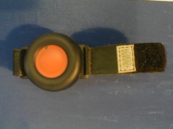
Click to zoom
Application Details
- Equipment Class
- DXX - Part 15 Low Power Communication Device Transmitter
- Date of Grant
- Apr 22, 2001
- Application Purpose
- Original Equipment
- Date of Application
- Mar 26, 2001
- Equipment Note
- Wrist Band w/Nurse Call
- Frequency Range
- 314.97000000 - 314.97000000
- Company
- Global DME,Inc.
- Country
- United States
Documents & Files
Document Text
Text extracted from the exhibit documents filed with the FCC. Open a document above to read the original.
Users Manual
User Manual Wireless wristband is worn by the resident and activates door monitoring system. • Waterproof • Shockproof • Long Life Residents wearing bracelets or pendants can call for help by simply pushing a button. A readout at nurse’s station shows which resident is in need of assistance, and gives their location. An optional local light alerts Caregivers.
External Photos
EUT Front View EUT Rear View
ID Label/Location Info
EUT FCC ID Label
ID Label/Location Info
EUT FCC ID Label Location
Internal Photos
EUT Circuit Board Component View EUT Circuit Board Solder View
Test Report
Note: This report may not be duplicated without prior written consent of Bay Area Compliance Laboratory Corporation. This report must not be used by the client to claim product endorsement by NVLAP or any agency of the U.S. Government. FCC ID PER PART 15.231 EMI MEASUREMENT AND TEST REPORT For Global DME, Inc. 619 Martin Ave. #6, Rohnert Park, CA 94928 FCC ID: PHNTXW01 March 6, 2001 This Report Concerns: Original Report Equipment Type: Wireless Nurse Call Emergency Response Test Engineer: Victor Liu Test Date: February 2, 2001 Reviewed By: John Y. Chan – Engineering Manager Prepared By: Bay Area Compliance Laboratory Corporation 230 Commercial Street, Suite 2 Sunnyvale, CA 94086 Tel: (408) 732-9162 Fax: (408) 732 9164 Global DME, Inc. FCC ID: PHNTXW01 Report # Test Report FCC Part 15.231 Test Report Page 2 of 16 TABLE OF CONTENTS 1 - GENERAL INFORMATION.................................................................................................................................................3 1.1 PRODUCT DESCRIPTION FOR EQUIPMENT UNDER TEST (EUT)........................................................................................3 1.2 OBJECTIVE................................................................................................................................................................................3 1.3 RELATED SUBMITTAL(S)/GRANT(S).....................................................................................................................................3 1.4 TEST METHODOLOGY..............................................................................................................................................................3 1.5 TEST FACILITY.........................................................................................................................................................................3 1.6 TEST EQUIPMENT LIST............................................................................................................................................................4 1.7 EQUIPMENT UNDER TEST (EUT)...........................................................................................................................................4 2 - SYSTEM TEST CONFIGURATION..................................................................................................................................5 2.1 JUSTIFICATION..........................................................................................................................................................................5 2.2 BLOCK DIAGRAM.....................................................................................................................................................................5 2.3 TEST SETUP BLOCK DIAGRAM...............................................................................................................................................6 2.4 EQUIPMENT MODIFICATIONS.................................................................................................................................................7 3 - CONDUCTED EMISSIONS TEST DATA........................................................................................................................8 4 - RADIATED EMISSION DATA............................................................................................................................................9 4.1 EUT SETUP...............................................................................................................................................................................9 4.2 SPECTRUM ANALYZER SETUP................................................................................................................................................9 4.3 TEST PROCEDURE....................................................................................................................................................................9 4.4 CORRECTED AMPLITUDE & MARGIN CALCULATION.........................................................................................................9 4.5 SUMMARY OF TEST RESULTS...............................................................................................................................................10 4.6 RADIATED EMISSIONS TEST RESULT DATA.......................................................................................................................10 5 –FCC 15.231 (A) TEST RESULT..........................................................................................................................................11 6 – MEASUREMENT OF BANDWIDTH..............................................................................................................................13 6.1 TEST OBJECTIVE/REQUIREMENT.........................................................................................................................................13 6.2 TEST SUMMARY.....................................................................................................................................................................13 6.3 PLOT(S) OF BANDWIDTH OF THE EMISSION.......................................................................................................................13 7 – BATTERY REQUIREMENT.............................................................................................................................................15 APPENDIX A – AGENCY AUTHORIZATION LETTER...............................................................................................16 Global DME, Inc. FCC ID: PHNTXW01 Report # Test Report FCC Part 15.231 Test Report Page 3 of 16 1 - GENERAL INFORMATION 1.1 Product Description for Equipment Under Test (EUT) The Global DME, Inc.’s model TXW01 or the "EUT" as referred to in this report is a 314.97 MHz periodic wireless nurse call which measures 1.5” L x 2” W x 0.5” H. 1.2 Objective This certification report is p…
Text truncated - open the document above for the full version.
Test Setup Photos
EUT Front View EUT Rear View
Contact Information
Applicant
Timothy Long(General Manager)
Technical Contact
Bay Area Compliance LaboratoryJohn Chan
[email protected](408)732-9162
230 Commercial St. Suite 2 · Sunnyvale, California · United States
Non-Technical Contact
Bay Area Compliance LaboratoryRita Cai
[email protected](408)732-9162
Test Firm
Bay Area Compliance LaboratoryJohn Chan
Technical Specifications
| # | Rule Parts | Frequency Range | Power Output |
|---|---|---|---|
| 1 | 15C | 314.97 MHz - 314.97 MHz | - |
Other Applications from Global DME,Inc.
PHNTL03RF
Mar 22, 2001Patient Monitoring Transmitter
Equipment Class
DXX - Part 15 Low Power Communication Device Transmitter