PJ4ID-900TRWireless Voice Recorder - Base
ID Fone Co., Ltd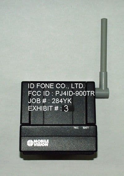
Click to zoom
Application Details
- Equipment Class
- DSS - Part 15 Spread Spectrum Transmitter
- Date of Grant
- Oct 10, 2001
- Application Purpose
- Original Equipment
- Date of Application
- Oct 10, 2001
- Equipment Note
- Wireless Voice Recorder - Base
- Frequency Range
- 902.00000000 - 928.00000000
- Company
- ID Fone Co., Ltd
- Country
- South Korea
Documents & Files
Document Text
Text extracted from the exhibit documents filed with the FCC. Open a document above to read the original.
Users Manual
900MHz SPREAD SPECTRUM T/R MODEL : ID-900TR 00-12-05 ID FONE Co., Ltd. 13 / 19 USER’S MANUAL 900MHz SPREAD SPECTRUM T/R MODEL : ID-900TR 00-12-05 ID FONE Co., Ltd 14 / 19 IMPORTANT Read this manual before attempting to setup or use this instrument. It contains important information regarding safe installation and use. Keep this manual for future reference. Also save the carton, packing and proof of purchase to simplify and accelerate any needed action. ! WARNING To prevent fire or shock hazard, do not expose this product to rain or any type of excess moisture. If accidentally dropped into water, this product should immediately be unplugged AC outlet and the telephone wall jack. ! THIS SYMBOL IS INTENDED TO ALERT THE USER OF THE PRESENCE OF IMPORTANT OPERATING AND MAINTENANCE (SERVICING) INSTRUCTIONS IN THE OWNER’S MANUAL. ! INSTALLATION PRECAUTIONS 1. Never install wiring during a lightning storm. 2. Never install jacks in wet locations unless the jack is specifically designed for wet locations. 3. Never touch uninsulated wires or terminals unless the telephone line has been disconnected at the network interface. 4. Use caution when installing or modifying telephone lines. ! MAINTENANCE 1. Use a damp cloth to clean the plastic cabinet. A mild soap will help to remove grease or oil. Never use polish, solvents, abrasives or strong detergents since these can damage the finish. 2. Your should be situated away from heat sources such as radiators, heaters, stoves or any other appliance that produces heat. ! CAUTION To reduce the risk of fire or injury to persons, read and follow these instructions: 1. Don’t Use the other type of battery. 900MHz SPREAD SPECTRUM T/R MODEL : ID-900TR 00-12-05 ID FONE Co., Ltd. 15 / 19 2. Do not dispose of the battery in a fire. The cell may explode. Check with local codes for possible special disposal instructions 3. Do not open or mutilate the battery. Released electrolyte is corrosive and may cause damage to the eyes or skin. It may be toxic if swallowed. 4. Exercise care in handling the battery in order not to short the battery with conducting material such as rings, bracelets and keys. The battery or conductor may overheat and cause burns. 5. Recharge only the battery type that is provided with or identified for use with this product. If a different type of battery is used, it may leak or explode. 6. Do not attempt to rejuvenate the battery provided with or identified for use with this product by heating them. Sudden release of the battery electrolyte may occur, causing burns or irritation to eyes or skin. 7. When inserting the battery into this product, the proper polarity or direction must be observed. Reverse insertion of battery may result in leakage or explosion. 8. Remove the battery from this product if the product will not be used for a long period of time (several months or more) since during this time they could leak in the product. 9. Discard the “dead” battery as soon as possible since “dead” battery are more likely to leak in a product. 10. Do not store this product, or the battery provided with or identified for use with this product, in high-temperature areas. Batteries that are stored in a freezer or refrigerator for the purpose of extending shelf life should be stabilized at room temperature prior to use after cold storage. 11. Always disconnect all line cords from the modular jacks before installing or replacing the battery. ! IMPORTANT SAFETY INSTRUCTIONS When using your equipment, basic safety precautions should always be followed to reduce the risk of fire, electric shock, and injury to persons, including the following: 1. Read and understand all instructions. 2. Follow all warnings and instructions marked on the product. 3. Unplug this product before cleaning. Do not use liquid cleaners or aerosol cleaners. Use a damp cloth for cleaning. 4. Do not use this product near water, for example, near a bathtub, wash bowl, kitchen sink, or laundry tub, in a wet basement or near a swimming pool. 5. Do not place this product on an unstable cart, stand, or table. The product may fall, 900MHz SPREAD SPECTRUM T/R MODEL : ID-900TR 00-12-05 ID FONE Co., Ltd 16 / 19 causing serious damage to the product. 6. Slots and openings in the cabinet and the back or bottom are provided for ventilation, to protect it from overheating. These openings should never be blocked by placing the product on the bed, sofa, rug, or other similar surface. This product should never be placed near or over a radiator or heat register. This product should not be placed in a built-in installation unless proper ventilation is provided. 7. This product should be operated only from the type of power source indicated on the marking label. If you are not sure of the type of power supply, consult your dealer or local power company. 8. Do not allow anything to rest on the power cord. Do not locate this product where the cord will be abused by persons walking on it. 9. Do not overload wall outlet and extension cords as this can result in the risk of fire or electric shock. 10. Never push objects of any kind into this product through cabinet slots as they may touch dangerous voltage points or short out parts that could result in a risk of fire or electric shock. Never spill liquid of any kind on the product. 11. To reduce the risk of electric shock, do not disassemble this product, but take it to a qualified service contractor when some service or repair work is required. Opening or removing covers may expose you to dangerous voltages or other risks. Incorrect reassembly can cause electric shock when the appliance is subsequently used. 12. Unplug this product from the wall outlet and refer servicing to qualified service personnel under the following conditions: A. When the power supply cord or plug is damaged or frayed. B. If liquid has been spilled into the product. C. If the product has been exposed to rain or water. D. If the product does not operate normally by following the operating …
Text truncated - open the document above for the full version.
Test Report
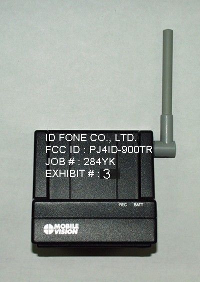
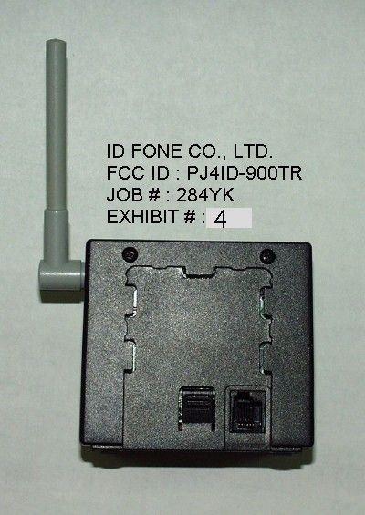
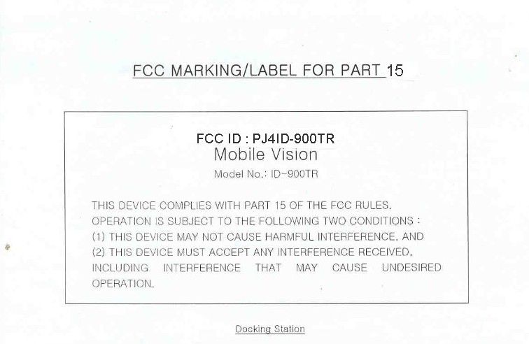
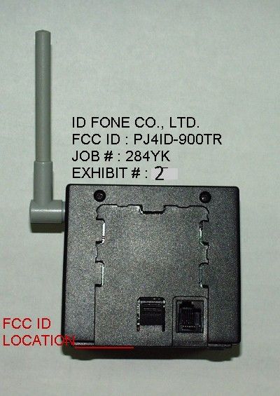
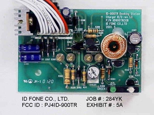
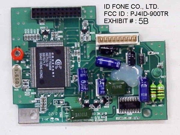
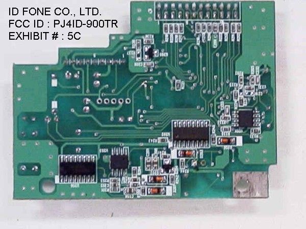
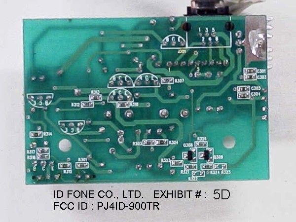
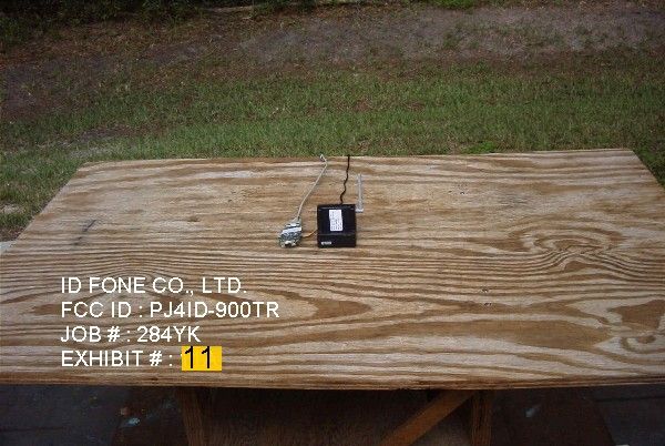
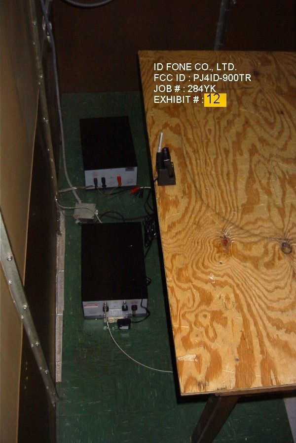
APPLICANT: ID FONE CO., LTD FCC ID: PJ4ID-900TR – BASE UNIT TABLE OF CONTENTS TEST REPORT CONTAINING: PAGE 1.............TEST EQUIPMENT LIST & TEST PROCEDURE PAGE 2.............TEST PROCEDURES CONTD. PAGE 3.............STATEMENT ABOUT ANTENNA AND PRODUCT DESC. PAGE 4A-4C.........POWERLINE CONDUCTED INTERFERENCE DATA AND PLOTS PAGE 5A............6.0dB BANDWIDTH & POWER OUTPUT PAGE 5B............6.0dB BANDWIDTH PLOT – BASE CHANNEL 1 PAGE 5C............6.0dB BANDWIDTH PLOT – BASE CHANNEL 10 PAGE 5D............6.0dB BANDWIDTH PLOT – BASE CHANNEL 20 PAGE 6.............METHOD OF MEASURING RF CONDUCTED SPURIOUS EMISSIONS & SPURIOUS EMISSIONS AT ANTENNA TERMINALS PAGE 7-8...........RADIATION INTERFERENCE TEST DATA PAGE 9.............METHOD OF MEASURING RADIATION INTERFERENCE PAGE 10............POWER SPECTRAL DENSITY & PROCESSING GAIN PAGE 10A...........POWER SPECTRAL DENSITY PAGE 10B...........BASE – CHANNEL 1 – 30dB ATT PAGE 10C...........BASE – CHANNEL 10 – 30dB ATT PAGE 10D...........BASE – CHANNEL 20 – 30dB ATT EXHIBIT ATTACHMENTS: EXHIBIT 1...........FCC ID LABEL SAMPLE EXHIBIT 2...........SKETCH OF FCC ID LABEL LOCATION EXHIBIT 3...........EXTERNAL PHOTO – FRONT VIEW EXHIBIT 4...........EXTERNAL PHOTO – REAR VIEW EXHIBIT 5A-5B.......INTERNAL PHOTOS – COMPONENT VIEW EXHIBIT 5C-5D.......INTERNAL PHOTOS – SOLDER VIEW EXHIBIT 6...........BLOCK DIAGRAM EXHIBIT 7A-7C.......SCHEMATICS EXHIBIT 8...........OPERATIONAL DESCRIPTION EXHIBIT 9...........USERS MANUAL EXHIBIT 10A-10B.....PROCESSING GAIN DATA EXHIBIT 11..........TEST SET UP PHOTO – RADIATED EXHIBIT 12..........TEST SET UP PHOTO – CONDUCTED APPLICANT: ID FONE CO., LTD FCC ID: PJ4ID-900TR REPORT #: T:\I\ID\284yk-base\284yk-base-TestReport.doc TABLE OF CONTENTS LIST TEST EQUIPMENT LIST 1. Spectrum Analyzer: HP 8566B-Opt 462, S/N 3138A07786, w/ preselector HP 85685A, S/N 3221A01400, Quasi-Peak Adapter HP 8565OA, S/N 3303A01690 & Preamplifier HP 8449B-OPT H02, S/N 3008A00372 2. Biconnical Antenna: Eaton Model 94455-1, S/N 1057, 3. Biconnical Antenna: Electro-Metrics Model BIA-25, S/N 1171 4. Log-Periodic Antenna: Electro-Metrics Model EM-6950, S/N 632 5. Log-Periodic Antenna: Electro-Metrics Model LPA-30, S/N 409 6. Double-Ridged Horn Antenna: Electro-Metrics Model RGA-180, 1-18 GHz, S/N 2319 7. 18-26.3GHz Systron Donner Standard Gain Horn #DBE-520-20 8. Horn 40-60GHz: ATM Part #19-443-6R 9. Line Impedance Stabilization Network: Electro-Metrics Model EM-7820, w/NEMA Adapter S/N 2682 Cal. 3/16/01 10. Temperature Chamber: Tenney Engineering Model TTRC, S/N 11717-7 11. Frequency Counter: HP Model 5385A, S/N 3242A07460 12. Peak Power Meter: HP Model 8900C, S/N 2131A00545 13. Open Area Test Site #1-3meters 14. Signal Generator: HP 8640B, S/N 2308A21464 15. Signal Generator: HP 8614A, S/N 2015A07428 16. Passive Loop Antenna: EMCO Model 6512, 9KHz to 30MHz, S/N 9706-1211 17. Dipole Antenna Kit: Electro-Metrics Model TDA-30/1-4, S/N 153 18. AC Voltmeter: HP Model 400FL, S/N 2213A14499 19. Digital Multimeter: Fluke Model 8012A, S/N 4810047 20. Digital Multimeter: Fluke Model 77, S/N 43850817 21. Oscilloscope: Tektronix Model 2230, S/N 300572 TEST PROCEDURE GENERAL: This report shall NOT be reproduced except in full without the written approval of TIMCO ENGINEERING, INC. Shielded interface cables were used in all cases except for cables connecting to the telephone line and the power cords. A test program was run which simulated a normal data transmission on a network. POWER LINE CONDUCTED INTERFERENCE: The procedure used was ANSI STAN- DARD C63.4-1992 using a 50uH LISN. Both lines were observed with the UUT transmitting. The bandwidth of the spectrum analyzer was 10kHz with an appropriate sweep speed. The ambient temperature of the UUT was 94ºF with a humidity of 35 %. APPLICANT: ID FONE CO., LTD FCCID: PJ4ID-900TR REPORT #: IT:\I\ID\284yk-base\284yk-base-TestReport.doc PAGE #: 1 TEST PROCEDURES CONTINUED BANDWIDTH 6.0dB: The measurements were made withe the spectrum analyz- er's resolution bandwidth(RBW)=100KHz and the video bandwidth(VBW) =300KHz and the span set as shown on plot. POWER OUTPUT: The RF power output was measured at the antenna feed point using a peak power meter. ANTENNA CONDUCTED EMISSIONS: The RBW=100KHz, VBW=300KHz and the span set to 10.0MHz and the spectrum was scanned from 30MHz to the 10th Harmonic of the fundamental. Above 1.0GHz the resolution bandwidth was 1.0MHz and the VBW = 3.0MHz and the span to 50MHz. RADIATION INTERFERENCE: The test procedure used was ANSI STANDARD C63.4-1992 using a HEWLETT PACKARD spectrum analyzer with a prese- lector. The bandwidth(RBW) of the spectrum analyzer was 100kHz up to 1GHz and 1.0MHz above 1GHz with an appropriate sweep speed. The VBW above 1.0GHz was = 3.0MHz. The analyzer was calibrated in dB above a microvolt at the output of the antenna. The ambient temperature of the UUT was 94oF with a humidity of 35%. APPLICANT: ID FONE CO., LTD FCCID: PJ4ID-900TR REPORT #: T:\I\ID\284yk-base\284yk-base-TestReport.doc PAGE #: 2 PRODUCT DESCRIPTION: This device is a 900 MHz DSSS wireless system that can be used by the Police Department to record dialog between the police and a suspect. When a policeman arrests a suspect, he must read the Miranda Rights to suspect. At the scene, a camcorder is recording the scene. This device will transmit the audio signal to the receiver which will be connected to the camcorder. Therefore, both the scene and sound can be recorded for future use. WIRELESS WIRELESS HANDSET BASE SET APPLICANT: ID FONE CO., LTD FCCID: PJ4ID-900TR REPORT #: T:\I\ID\284yk-base\284yk-base-TestReport.doc PAGE #: 3 APPLICANT: ID FONE CO., LTD FCC ID: PJ4ID-900TR NAME OF TEST: POWER LINE CONDUCTED INTERFERENCE RULES PART NUMBER: 15.107(a) REQUIREMENTS: .45 - 30 MHz 250 uV OR 47.96 dBuV TEST PROCEDURE: ANSI STANDARD C63.4-1992. The spectrum was scanned from .45 to 30 MHz. TEST DATA: THE HIGHEST EMISSION READ FOR LINE 1 WAS 18.8 uV @ 28.88 MHz. THE HIGHEST EMISSION READ FOR LINE 2 WAS 19.1 uV @ 9…
Text truncated - open the document above for the full version.
Test Report
1.Processing Gain THE TEST SETUPS: This section provides measurement guidelines for Direct Sequence Spread Spectrum serial port from a computer to the DCT UUT is needed to force selection of output power level and channel. Section 15,247(0):Processing Gain. The processing gain may be measured using the CW jamming margin method. Figure 1 shows the test configuration. The test consists of stepping a signal generator in 50 KHz increments across the pass band of the system (up to 960 KHz away in Rl's DCT). At each point, the generator level required to produce the recommended Bit Error Rate(BER) (Set at BER=10-³) is recorded. This level is the jamming level. The output power of the transmitting unit is measured at the same point. The jammer to Signal (J/S) ratio is then calculated. Discard the worst 20% of the J/S data point. The lowest remaining J/S ratio is used to calculate the processing gain. The maximum implementation loss a system can claim in calculating processing gain is 2dB. The equation to calculate the processing gain (Gp) is the following. Gp = (S/N)o + Mj + Lsys Where Lsys = system implementation loss = 2dB. Mj= jamming margin (J/S) in dB. (S/N)o = signal to noise ratio required for a DBPSK system with BER of 10-³ = 8.0dB Figure 1 : Jamming Test Setup MODEL : HD -950 S = Signal Power - Attn - Comb loss - cable Loss = 4.0 - 19.8 - 3.6 - 0.5 = -27.9 dB J = Sig Gen O/P[v](N) -cal factor - Comb Loss = N - 0.3 - 3.6 dB DCT H/S Transmitter 19.8dB Pad Pwr Combiner Va r. Atten. DCT B/S Receiver Noise Source BER Tester IID FONE CO., LTD. FCC ID : PJ4ID-900TR JOB # : 284YK EXHIBIT # : 10A Jammer Freq(MHz) Signal Ly dB CW Noise N dB Mj J/S dB Proc.Gain dB 915.6 -27.9 -15.1 8.8 19 915.65 -27.9 -15 8.9 19.1 915.7 -27.9 -22.9 1 11.2 915.75 -27.9 -19.9 4 14.2 915.8 -27.9 -19.6 4.3 14.5 915.85 -27.9 -20.3 3.6 13.8 915.9 -27.9 -21.3 2.6 12.8 915.95 -27.9 -19.3 4.6 14.8 916 -27.9 -21 2.9 13.1 916.05 -27.9 -11.8 12.1 22.3 916.1 -27.9 -19.5 4.4 14.6 916.15 -27.9 -11.8 12.1 22.3 916.2 -27.9 -17 6.9 17.1 916.25 -27.9 -14.2 9.7 19.9 916.3 -27.9 -12.5 11.4 21.6 916.35 -27.9 -10 13.9 24.1 916.4 -27.9 -6 19.9 28.1 916.45 -27.9 -4 22.7 30.1 916.5 -27.9 -1.2 22.1 32.9 916.55 -27.9 -1.8 32.3 2.Data Rate 80 Kb/s Time Division Duplex (TDD) 32K Transmit + 32K Receive + Overhead 3.Chip Rate 960 Kchips/s (12 chips per bit) DSSS 4.Sampling Rate 1.92 Msamples/s (2 samples/chip) PROCESSING GAIN CONT.’D EXHIBIT # : 10B
Contact Information
Applicant
Jun-Yong Park(Assistant Manager)
Test Firm
Timco Engineering, Inc.S Sanders
Technical Specifications
| # | Rule Parts | Frequency Range | Power Output |
|---|---|---|---|
| 1 | 15C | 902 MHz - 928 MHz | 49.00 mW |
Other Applications from ID Fone Co., Ltd
PJ4ID-2400TRB
Nov 21, 2002Spread Spectrum Wireless Recorder - Base
Equipment Class
DSS - Part 15 Spread Spectrum Transmitter
PJ4ID-2400TR
Nov 21, 2002Spread Spectrum Wireless Recorder - Handset
Equipment Class
DSS - Part 15 Spread Spectrum Transmitter