PJ7-1232GPRS Module
Shenzhen Neoway Technology Co., Ltd.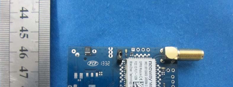
Click to zoom
Application Details
- Equipment Class
- PCB - PCS Licensed Transmitter
- Date of Grant
- Mar 19, 2014
- Application Purpose
- Original Equipment
- Date of Application
- Mar 19, 2014
- Equipment Note
- GPRS Module
- Frequency Range
- 1850.20000000 - 1909.80000000
- Country
- China
Documents & Files
Document Text
Text extracted from the exhibit documents filed with the FCC. Open a document above to read the original.
Users Manual
Neo_M680 Hardware User Guide Version 1.0 Let's enjoy the wireless life Neo_M680 Hardware User Guide V1.0 Copyright Neoway Techlology Co., Ltd. Page 2 of 31 Copyright Copyright © 2008 Neoway Technology All rights reserved. is a trade mark of Neoway Technology Co., Ltd. Notice This document is intended for the customer engineers. This document is subject to change without any notice. No responsibility is assumed by Neoway Technology for the use of this document. Neoway Technology always provides the best supports. For pricing, delivery, and ordering information please contact: [email protected] For any technical support requests please contact: [email protected] For further information please visit: http://www.neoway.com.cn Neo_M680 Hardware User Guide V1.0 Copyright Neoway Techlology Co., Ltd. Page 3 of 31 Contents Copyright ............................................................................................................................................ 2 1. Introduction ................................................................................................................................ 6 2. General Description ................................................................................................................... 6 3. Simplified Block Diagram ......................................................................................................... 6 4. Key Features ............................................................................................................................... 7 5. Product Specifications ............................................................................................................... 8 5.1 Variants ................................................................................................................................. 8 5.2 Dimension & Package ........................................................................................................... 8 5.3 Pin Description ...................................................................................................................... 9 5.4 PCB foot print ..................................................................................................................... 12 6. Application Interface ............................................................................................................... 13 6.1 Power Supply Requirements ................................................................................................ 13 6.1.1 Power Supply Basic Design Rules ........................................................................ 13 6.1.2 Extended Design Rules for Power Supply: ........................................................... 15 6.2 ON/OFF Procedure ............................................................................................................. 17 6.2.1 Turning on the module: ......................................................................................... 18 6.2.2 Turning off the module: ........................................................................................ 18 6.2.3 RESET .................................................................................................................. 19 6.2.4 VMC ..................................................................................................................... 19 6.3 UART .................................................................................................................................. 20 6.3.1 Basic Descriptions of UART ................................................................................. 20 6.3.2 Level Translators for UART .................................................................................. 20 6.4 Sleep mode .......................................................................................................................... 22 6.4.1 DTR ....................................................................................................................... 22 6.4.2 RING ..................................................................................................................... 23 6.5 SIM interface ...................................................................................................................... 23 6.6 Running LED Indicator ....................................................................................................... 25 6.7 Audio Interface ................................................................................................................... 26 6.8 Antenna Interface ................................................................................................................ 28 7. Mounting the Module onto the Application Board ............................................................... 30 Neo_M680 Hardware User Guide V1.0 Copyright Neoway Techlology Co., Ltd. Page 4 of 31 8. Package ..................................................................................................................................... 30 9. Terms and Abbreviations ......................................................................................................... 31 Neo_M680 Hardware User Guide V1.0 Copyright Neoway Techlology Co., Ltd. Page 5 of 31 Document History Revision History Version Remarks Date Issue V1.0 Initial Version 2013-9 Neo_M680 Hardware User Guide V1.0 Copyright Neoway Techlology Co., Ltd. Page 6 of 31 1. Introduction This document describes the hardware features of M680, and guides for the relevant application design. 2. General Description With the ultra-compact design, M680 is intended to be used in a wide range of applications, including industrial and consumer devices. M680 is a GSM/GPRS module with EDGE of downlink. It features with voice, SMS, and data services. 3. Simplified Block Diagram Figure 1 M680 Block Diagram Baseband Controller PA Power Manager Application Interface RF Section FLASH Audio Section SIM UART x 2…
Text truncated - open the document above for the full version.
Cover Letter(s)
Shenzhen Neoway Technology Co.,Ltd AUTHORIZATION LETTER FCC ID: PJ7-1232 Date: Jan 30, 2014 To whom it may concern: We the undersigned, hereby authorize Shenzhen Huatongwei International Inspection Co., Ltd to act on our behalf in all manners relating to application for equipment authorization, including signing of all documents relating to these matters. Any and all acts carried out by Shenzhen Huatongwei International Inspection Co., Ltd on our behalf shall have the same affect as acts of our own. This authorization shall expire 6 months from orignal data. If you have any questions regarding the authorization, please don’t hesitate to contact us. Sincerely, Xinhui Lin/ Technical Coordinator Certification Shenzhen Neoway Technology Co.,Ltd Tel: +86 18719287694 Fax: +86 755-29672566 E-mail: [email protected]
Cover Letter(s)
Shenzhen Neoway Technology Co.,Ltd Shenzhen Neoway Technology Co.,Ltd FCC ID:PJ7-1232 Date: Jan 30, 2014 Federal Communications Commission 7435 Oakland Mills Road Columbia, MD 21046 Gentlemen: This letter is to comply with Sections 0.457 and 0.459 pertaining to confidential material. Shenzhen Neoway Technology Co.,Ltd would like the following documents regarding this submission for FCC ID: PJ7-1232 to be kept confidential. 1. Block Diagram 2. Schematic 3. Theory of Operation 4. Part List 5. Tune up Procedure The above material contains trade secrets or technical data, which would customarily be guarded from competitors. We do not want these documents to be accessible to the general public. Sincerely, Xinhui Lin/ Technical Coordinator Certification Shenzhen Neoway Technology Co.,Ltd Tel: +86 18719287694 Fax: +86 755-29672566 E-mail: [email protected]
Cover Letter(s)
Shenzhen Neoway Technology Co.,Ltd Shenzhen Neoway Technology Co.,Ltd FCC ID: PJ7-1232 Date: Jan 30, 2014 Ref:Application Single Modular Approval Certification for Product Type:GPRS Module,Model: M680 ;FCC ID : PJ7-1232 We , Shenzhen Neoway Technology Co.,Ltd hereby clarify the following attestation addresses the fourth requirements to support modular approval: 1. This devices is designed for mobile or fixed operation;Portable operation is subject to a class II permissive change application or to a new and separate FCC ID; 2. The maximum antenna is limited to 1.00dBi for both 850MHz and 1900MHz frequency band,as calculated in the RF exposure test report; 3. The product has a FCC ID label on the device itself.Also,the OEM host end product manufacturer will be informed to display a label referring to the enclosed module.The exterior label will read as follows:”Contains FCC ID:PJ7-1232”. 4. We request to include in the Grant the following words in device description or Grant noters:”Modular transmitter”,or “transmitter module”; If there are any additional questions or if further information is needed,please contact us. Sincerely, Xinhui Lin/ Technical Coordinator Certification Shenzhen Neoway Technology Co.,Ltd Tel: +86 18719287694 Fax: +86 755-29672566 E-mail: [email protected]
Cover Letter(s)
Shenzhen Neoway Technology Co.,Ltd FCC ID: PJ7‐1232 Date: Jan 30, 2014 Request for Single Modular Approval Attestation for the Module (FCC ID: PJ7‐1232) (i) The radio elements of the modular transmitter must have their own shielding. The physical crystal and tuning capacitors may be located ex‐ternal to the shielded radio elements. Yes, The modular transmitter has its own shielding as shown on the external photo exhibits. (ii) The modular transmitter must have buffered modulation/data inputs. Yes,the modular has its digital buffered data inputs. (iii) The modular transmitter must have its own power supply regulation. Yes,The modular has its own regulation power supply; (iv) The modular transmitter must comply with the antenna and transmission system requirements of §§15.203, 15.204(b) and 15.204(c). The antenna must either be permanently attached or employ a ‘‘unique’’ antenna coupler (at all connections between the module and the antenna, including the cable). The ‘‘professional installation’’ provision of §15.203 is not applicable to modules but can apply to limited modular approvals under paragraph (b) of this section. Yes,Not applicable to licensed module.The GPRS module has been tested with external antenna. (v) The modular transmitter must be tested in a stand‐alone configuration, i.e., the module must not be inside an‐other device during testing for compliance with part 15 requirements. Unless the transmitter module will be battery powered, it must comply with the AC line conducted requirements found in §15.207. AC or DC power lines and data input/output lines connected to the module must not contain ferrites, un‐less they will be marketed with the module (see §15.27(a)). The length of these lines shall be the length typical of actual use or, if that length is unknown, at least 10 centimeters to insure that there is no coupling between the case of the module and supporting equipment. Any accessories, peripherals, or support equipment connected to the module during testing shall be unmodified and commercially available. Yes, The modular transmitter has been tested in stand‐alone configuration,please see RF test report and test setup photo. (vi) The modular transmitter must be equipped with either a permanently affixed label or must be capable of electronically displaying its FCC identification number. (A) If using a permanently affixed label, the modular transmitter must be labeled with its own FCC identification number, and, if the FCC identification number is not visible when the module is installed inside another device, then the outside of the device into which the module is installed must also display a label referring to the enclosed module. This exterior label can use wording such as the following: ‘‘Contains Trans‐mitter Module FCC ID: XYZMODEL1’’ or ‘‘Contains FCC ID: XYZMODEL1.’’ Any similar wording that expresses the same meaning may be used. The Grant‐ee may either provide such a label, an Shenzhen Neoway Technology Co.,Ltd example of which must be included in the application for equipment author‐ization, or, must provide adequate in‐structions along with the module which explain this requirement. In the latter case, a copy of these instructions must be included in the application for equipment authorization. (B) If the modular transmitter uses an electronic display of the FCC identi‐fication number, the information must be readily accessible and visible on the modular transmitter or on the device in which it is installed. If the module is installed inside another device, then the outside of the device into which the module is installed must displaya label referring to the enclosed module. This exterior label can use wording such as the following: ‘‘Contains FCC certified transmitter module(s).’’ Any similar wording that expresses the same meaning may be used. The user manual must include instructions on how to access the electronic display. A copy of these instructions must be in‐cluded in the application for equipment authorization. Yes,the modular with own FCC ID: PJ7‐1232 will be labeled onto the modular transmitter. (vii) The modular transmitter must comply with any specific rules or operating requirements that ordinarily apply to a complete transmitter and the manufacturer must provide adequate instructions along with the module to explain any such requirements. A copy of these instructions must be included in the application for equipment authorization. Yes, The modular transmitter is compliant with part 22H and 24E. Installation and other requirements are presented in the manual . (viii) The modular transmitter must comply with any application RF exposure requirements. Yes, The modular transmitter meet RF exposure requirements,please see RF Exposure Test Report. Sincerely, Xinhui Lin/ Technical Coordinator Certification Shenzhen Neoway Technology Co.,Ltd Tel: +86 18719287694 Fax: +86 755-29672566 E‐mail: [email protected]
External Photos
External photos of the EUT
ID Label/Location Info
Label and Label Location 15mm
Internal Photos
Internal photos of the EUT
Parts List/Tune Up Info
TUNE-UP PROCEDURE 2.1033 (c)(9) Tune-Up Procedure and Power Tune-Up – Power Limiting 1. It must provide an operational voltage to turn on the GPRS module and on one certain channel in service mode by means of company proprietary software. 2. Base station simulator (Rohde& Schwarz CMU200 or Agilent 8960) measures the GRPS module specific RF characteristics. 3. The maximum gain of each individual Camera is adjusted until the target value met. For GSM 850 Class 5 MAX PWR = 33 dBm For GSM1900 Class 0 MAX PWR = 30 dBm RX sensitivity < -102Bm Then these appropriate gain settings are stored in each GPRS Module individually. The user has no possibility to change these settings later on, and during manufacturing each phone will be individual calibrated. The measurement is done in fully calibrated setup, which is based on a Rohde& Schwarz CMU200 base station simulator. Furthermore, the highest power level is verified afterwards in a call measurement on three channels (low, middle and high). GPRS/EGPRS (GMSK Modulation) GSM850 GPRS Channel 251 190 128 1 Txslot Target (dBm) 32.00 32.00 32.00 Tolerance ±(dB) 1 1 1 2 Txslot Target (dBm) 29.50 29.50 29.50 Tolerance ±(dB) 1 1 1 3 Txslot Target (dBm) 27.50 27.50 27.50 Tolerance ±(dB) 1 1 1 4 Txslot Target (dBm) 26.50 26.50 26.50 Tolerance ±(dB) 1 1 1 GSM850 EDGE Channel 251 190 128 1 Txslot Target (dBm) 31.50 31.50 31.50 Tolerance ±(dB) 1 1 1 2 Txslot Target (dBm) 29.50 29.50 29.50 Tolerance ±(dB) 1 1 1 3 Txslot Target (dBm) 27.50 27.50 27.50 Tolerance ±(dB) 1 1 1 4 Txslot Target (dBm) 26.50 26.50 26.50 Tolerance ±(dB) 1 1 1 GSM1900 GPRS Channel 810 661 512 1 Txslot Target (dBm) 29.00 29.00 29.00 Tolerance ±(dB) 1 1 1 2 Txslot Target (dBm) 26.50 26.50 26.50 Tolerance ±(dB) 1 1 1 3 Txslot Target (dBm) 24.50 24.50 24.50 Tolerance ±(dB) 1 1 1 4 Txslot Target (dBm) 23.50 23.50 23.50 Tolerance ±(dB) 1 1 1 GSM1900 EDGE Channel 810 661 512 1 Txslot Target (dBm) 29.00 29.00 29.00 Tolerance ±(dB) 1 1 1 2 Txslot Target (dBm) 26.50 26.50 26.50 Tolerance ±(dB) 1 1 1 3 Txslot Target (dBm) 24.50 24.50 24.50 Tolerance ±(dB) 1 1 1 4 Txslot Target (dBm) 23.50 23.50 23.50 Tolerance ±(dB) 1 1 1 Tune Up Procedure 1. RX Gain Calibration a. Put DUT in test mode b. Put DUT in BCH mode c. Put DUT in selected channel band d. Total gain chain calibration at center ARFCN e. Frequency Ripple calibration f. Complete RX_AGC Gain table 2. TX Power Calibration a. Put DUT in test mode b. Put DUT in BCH mode c. Put DUT in selected channel band d. Calibrate Rampscale value at center ARFCN e. Frequency Ripple calibration f. Complete TX_APC table 3. AFC calibration a. Put DUT in test mode b. Put DUT in selected channel band c. Calibrate AFC at center ARFCN d. Complete AFC result table
RF Exposure Info
MPE TEST REPORT FCC Per 47 CFR 2.1091(b) Report Reference No. .................... : FCC ID. ............................................ : TRE1312005402 R/C: 30385 PJ7-1232 Compiled by ( position+printed name+signature) .. : File administrators Jerome Luo Supervised by ( position+printed name+signature) .. : Test Engineer Yuchao Wang Approved by ( position+printed name+signature) .. : Manager Wenliang Li Date of issue ..................................... : Jan 14, 2014 Testing Laboratory Name .............. : Shenzhen Huatongwei International Inspection Co., Ltd Address ............................................. : Keji Nan No.12 Road, Hi-tech Park, Shenzhen, China Applicant’s name ............................ : Shenzhen Neoway Technology Co.,Ltd Address ............................................. : 4F-2#,Lianjian Science & Industry Park,Huarong Road,Dalang,Longhua new district,Shenzhen.P.R.C Test specification .......................... : Standard ........................................... : FCC Per 47 CFR 2.1091(b) KDB447498 v05r02 TRF Originator .................................. : Shenzhen Huatongwei International Inspection CO., Ltd Master TRF ....................................... : Dated 2006-06 Shenzhen Huatongwei International Inspection Co., Ltd. All rights reserved. This publication may be reproduced in whole or in part for non-commercial purposes as long as the Shenzhen Huatongwei International Inspection Co., Ltd is acknowledged as copyright owner and source of the material. Shenzhen Huatongwei International Inspection Co., Ltd takes no responsibility for and will not assume liability for damages resulting from the reader's interpretation of the reproduced material due to its placement and context. Test item description .................... : GPRS Module Trade Mark ....................................... : Manufacturer ................................... : Shenzhen Eternity Technology Co.,Ltd Model/Type reference ....................... : M680 Listed Models .................................. : / Ratings .............................................. : DC 3.90V Modulation ....................................... : GMSK for GPRS/EDGE GPRS/ EGPRS Class ........................ 12 GPRS operation mode ...................... Class B Frequency .......................................... GSM 850MHz; PCS 1900MHz; Result ................................................ : PASS Report No.: TRE1312005402 Page 2 of 8 Issued:2014-01-14 MPE T E S T R E P O R T Test Report No. : TRE1312005402 Jan 14, 2014 ______________________________________________________________________________________________ Date of issue Equipment under Test : GPRS Module Model /Type : M680 Listed Models : / Applicant : Shenzhen Neoway Technology Co.,Ltd Address : 4F-2#,Lianjian Science & Industry Park,Huarong Road,Dalang,Longhua new district,Shenzhen.P.R.C Manufacturer Shenzhen Eternity Technology Co.,Ltd Address : Block A2,Yingzhan Industrial Zone, Longtian Community, KengziOffice,Pingshan New District,Shenzhen,Guangdong Province,P.R.China Test Result PASS The test report merely corresponds to the test sample. It is not permitted to copy extracts of these test result without the written permission of the test laboratory. Report No.: TRE1312005402 Page 3 of 8 Issued:2014-01-14 Contents 1. SUMMARY 4 1.1. EUT configuration 4 1.2. NOTE 4 2. TEST ENVIRONMENT 5 2.1. Address of the test laboratory 5 2.2. Environmental conditions 5 2.3. Statement of the measurement uncertainty 5 3. METHOD OF MEASUREMENT 5 3.1. Applicable Standard 5 3.2. Limit 6 3.3. MPE Calculation Method 6 4. CONCLUSION 8 Report No.: TRE1312005402 Page 4 of 8 Issued:2014-01-14 1. SUMMARY 1.1. EUT configuration The following peripheral devices and interface cables were connected during the measurement: ● - supplied by the manufacturer ○ - supplied by the lab ○ Power Cable Length (m) : / Shield : / Detachable : / ○ Multimeter Manufacturer : / Model No. : / 1.2. NOTE 1. The EUT is a GPRS Module,The functions of the EUT listed as below: Test Standards Reference Report GPRS/EDGE FCC Part 22/FCC Part 24 TRE1312005401 MPE FCC Part 2.1091(d) TRE1312005402 . Report No.: TRE1312005402 Page 5 of 8 Issued:2014-01-14 2. TEST ENVIRONMENT 2.1. Address of the test laboratory Shenzhen Huatongwei International Inspection Co., Ltd Keji Nan No.12 Road, Hi-tech Park, Shenzhen, China Phone: 86-755-26715686 Fax: 86-755-26748089 The sites are constructed in conformance with the requirements of ANSI C63.7, ANSI C63.4 (2009) and CISPR Publication 22. 2.2. Environmental conditions During the measurement the environmental conditions were within the listed ranges: Temperature: 15-35 ° C Humidity: 30-60 % Atmospheric pressure: 950-1050mbar 2.3. Statement of the measurement uncertainty The data and results referenced in this document are true and accurate. The reader is cautioned that there may be errors within the calibration limits of the equipment and facilities. The measurement uncertainty was calculated for all measurements listed in this test report acc. to TR-100028-01” Electromagnetic compatibility and Radio spectrum Matters (ERM);Uncertainties in the measurement of mobile radio equipment characteristics; Part 1” and TR-100028-02 “Electromagnetic compatibility and Radio spectrum Matters (ERM);Uncertainties in the measurement of mobile radio equipment characteristics; Part 2 “ and is documented in the Shenzhen Huatongwei International Inspection Co., Ltd quality system acc. to DIN EN ISO/IEC 17025. Furthermore, component and process variability of devices similar to that tested may result in additional deviation. The manufacturer has the sole responsibility of continued compliance of the device. Hereafter the best measurement capability for Shenzhen Huatongwei laboratory is reported: Test Items Measurement Uncertainty Notes Transmitter power conducted 0.57 dB (1) (1) This uncertainty represents an expanded uncertainty expressed at approximately the 95% confidence level usi…
Text truncated - open the document above for the full version.
Test Report
FCC PART 22/24 TEST REPORT FCC Part 22 /Part 24 Report Reference No. .................... : FCC ID. ............................................ : TRE1312005401 R/C: 30385 PJ7-1232 Compiled by ( position+printed name+signature) .. : File administrators Jerome Luo Supervised by ( position+printed name+signature) .. : Test Engineer Yuchao Wang Approved by ( position+printed name+signature) .. : Manager Wenliang Li Date of issue ..................................... : Jan 14, 2014 Testing Laboratory Name .............. : Shenzhen Huatongwei International Inspection Co., Ltd Address............................................. : Keji Nan No.12 Road, Hi-tech Park, Shenzhen, China Applicant’s name ............................ : Shenzhen Neoway Technology Co.,Ltd Address............................................. : 4F-2#,Lianjian Science & Industry Park,Huarong Road,Dalang,Longhua new district,Shenzhen.P.R.C Test specification .......................... : Standard ........................................... : FCC Part 22: PUBLIC MOBILE SERVICES FCC Part 24: PERSONAL COMMUNICATIONS SERVICES TRF Originator .................................. : Shenzhen Huatongwei International Inspection CO., Ltd Master TRF ....................................... : Dated 2006-06 Shenzhen Huatongwei International Inspection Co., Ltd. All rights reserved. This publication may be reproduced in whole or in part for non-commercial purposes as long as the Shenzhen Huatongwei International Inspection Co., Ltd is acknowledged as copyright owner and source of the material. Shenzhen Huatongwei International Inspection Co., Ltd takes no responsibility for and will not assume liability for damages resulting from the reader's interpretation of the reproduced material due to its placement and context. Test item description .....................: GPRS Module Trade Mark ....................................... : Manufacturer ................................... : Shenzhen Eternity Technology Co.,Ltd Model/Type reference ....................... : M680 Listed Models .................................. : / Ratings.............................................. : DC 3.90V Modulation ....................................... : GMSK for GSM/GPRS/EDGE GPRS Class ...................................... 12 GPRS operation mode ...................... Class B Frequency Band ................................ GPRS850/EDGE850/GPRS1900/EDGE1900 Result ................................................ : PASS Report No.: TRE1312005401 Page 2 of 72 Issued:2014-01-14 T E S T R E P O R T Test Report No. : TRE1312005401 Nov 23, 2013 ______________________________________________________________________________________________ Date of issue Equipment under Test : GPRS Module Model /Type : M680 Listed Models : / Applicant : Shenzhen Neoway Technology Co.,Ltd Address : 4F-2#,Lianjian Science & Industry Park,Huarong Road,Dalang,Longhua new district,Shenzhen.P.R.C Manufacturer : Shenzhen Eternity Technology Co.,Ltd Address : Block A2,Yingzhan Industrial Zone, Longtian Community, KengziOffice,Pingshan New District,Shenzhen,Guangdong Province,P.R.China Test Result PASS The test report merely corresponds to the test sample. It is not permitted to copy extracts of these test result without the written permission of the test laboratory. Report No.: TRE1312005401 Page 3 of 72 Issued:2014-01-14 Contents 1. TEST STANDARDS .................................................................. 4 2. SUMMARY ............................................................................. 5 2.1. General Remarks 5 2.2. Product Description 5 2.3. Equipment under Test 5 2.4. Short description of the Equipment under Test (EUT) 5 2.5. Internal Identification of AE used during the test 6 2.6. Normal Accessory setting 6 2.7. EUT configuration 6 2.8. Related Submittal(s) / Grant (s) 6 2.9. Modifications 6 2.10. Note 6 3. TEST ENVIRONMENT ............................................................... 7 3.1. Address of the test laboratory 7 3.2. Test Facility 7 3.3. Environmental conditions 8 3.4. Statement of the measurement uncertainty 8 3.5. Test Description 8 3.6. Equipments Used during the Test 9 4. TEST CONDITIONS AND RESULTS ............................................ 10 4.1. Conducted Emissions Test 10 4.2. OUTPUT POWER 12 4.3. Radiated Spurious Emssion 17 4.4. OCCUPIED BANDWIDTH 21 4.5. EMISSION BANDWIDTH 29 4.6. BAND EDGE COMPLIANCE 37 4.7. Spurious Emssion on Antenna Port 43 4.8. Frequency Stability Test 66 5. TEST SETUP PHOTOS OF THE EUT .......................................... 68 6. EXTERNAL AND INTERNAL PHOTOS OF THE EUT ....................... 70 Report No.: TRE1312005401 Page 4 of 72 Issued:2014-01-14 1. TEST STANDARDS The tests were performed according to following standards: FCC Part 22 (10-1-12 Edition): PRIVATE LAND MOBILE RADIO SERVICES. FCC Part 24(10-1-12 Edition): PUBLIC MOBILE SERVICES TIA/EIA 603 D June 2010: Land Mobile FM or PM Communications Equipment Measurement and Performance Standards. FCC Part 2: FREQUENCY ALLOCA-TIONS AND RADIO TREATY MAT-TERS; GENERAL RULES AND REG-ULATIONS KDB971168 D01:201: Procedures for Compliance Measurement of the Fundamental Emission Power of Licensed Wideband (> 1 MHz) Digital Transmission Systems ANSI C63.4:2009: Methods of Measurement of Radio-Noise Emissions from Low-Voltage Electrical and Electronic Equipment in the Range of 9 kHz to 40 GHz Report No.: TRE1312005401 Page 5 of 72 Issued:2014-01-14 2. SUMMARY 2.1. General Remarks Date of receipt of test sample : Dec12, 2013 Testing commenced on : Jan 13, 2014 Testing concluded on : Jan 14, 2014 2.2. Product Description The Shenzhen Neoway Technology Co.,Ltd’s Model: M680 or the “EUT” as referred to in this report; more general information as follows, for more details, refer to the user’s manual of the EUT. Name of EUT GPRS Module Model Number M680 FCC ID PJ7-1232 Modilation Type GMSK for GPRS/EDGE Antenna Type External Voice Function Not Supported Voice function GSM/EDGE/GPRS …
Text truncated - open the document above for the full version.
Test Setup Photos
Test setup photos of the EUT
Contact Information
Applicant
Jesse Yuan(Certification Manager)
Test Firm
Shenzhen Huatongwei International Insp. Co., LtdMoffy Yu
Technical Specifications
| # | Rule Parts | Frequency Range | Power Output | Emission | Tolerance |
|---|---|---|---|---|---|
| 2 | 24E | 1.85 GHz - 1.91 GHz | 995.40 mW | 248KGXW | 0.027 ppm |
Other Applications from Shenzhen Neoway Technology Co., Ltd.
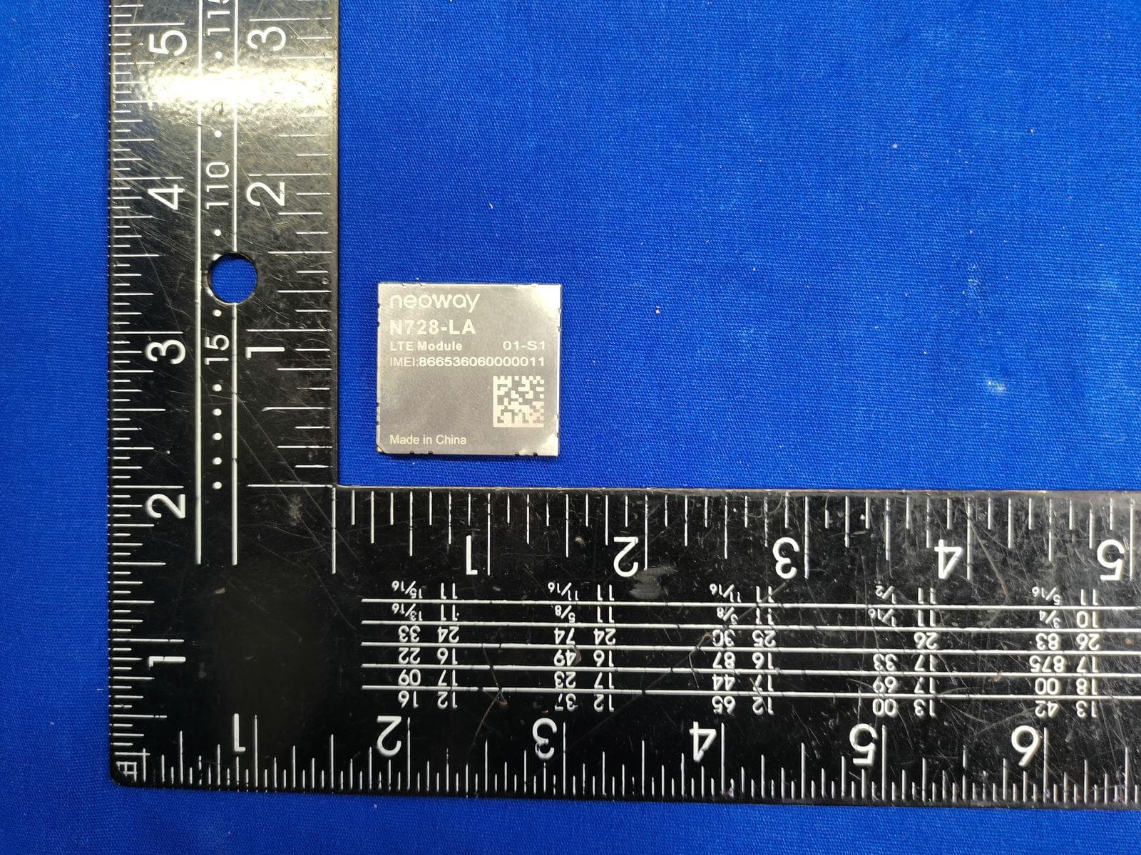
PJ7-N728LA
Aug 05, 2023LTE Module
Equipment Class
PCB - PCS Licensed TransmitterPJ7-N2110-AM
Jul 13, 2020LTE OBD dongle
Equipment Class
JAB - Part 15 Class B Digital Device
PJ7-N2610-US
Jul 09, 2020LTE OBD dongle
Equipment Class
JAB - Part 15 Class B Digital Device
PJ7-N27-W3
Apr 28, 2020Cat.M1 Module
Equipment Class
PCB - PCS Licensed Transmitter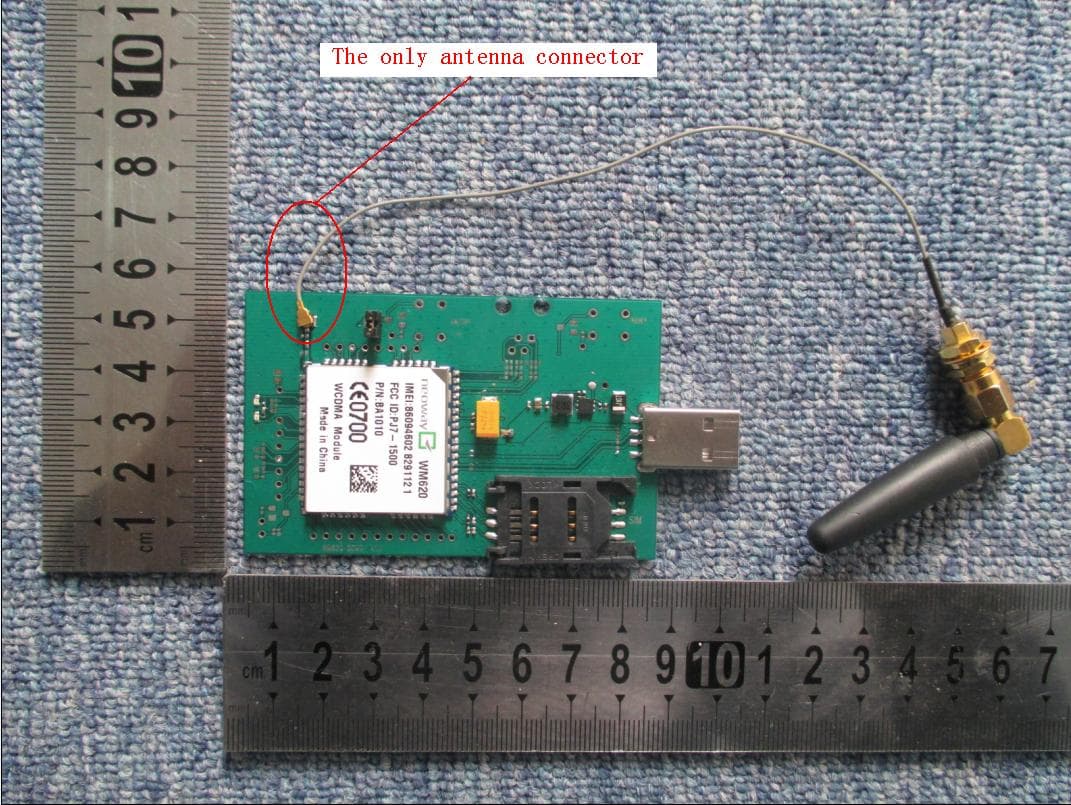
PJ7-1500
Jan 09, 2014WCDMA Module
Equipment Class
PCB - PCS Licensed Transmitter