PJ9TX111Remote Relay (Transmitter)
Dynamco Pty. Ltd.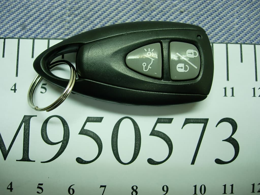
Click to zoom
Application Details
- Equipment Class
- DSC - Part 15 Security/Remote Control Transmitter
- Date of Grant
- May 23, 2006
- Application Purpose
- Original Equipment
- Date of Application
- May 23, 2006
- Equipment Note
- Remote Relay (Transmitter)
- Frequency Range
- 433.00000000 - 433.00000000
- Company
- Dynamco Pty. Ltd.
- Country
- Australia
Documents & Files
Document Text
Text extracted from the exhibit documents filed with the FCC. Open a document above to read the original.
Users Manual
PARALYSER 275 USER INSTRUCTIONS CYCLPS R U I C T Y E S S S Y S M TE Proudly designed and engineered in Australia by Dynamco Pty Ltd. Immobiliser Vehicle Security System CYCLOPS PARALYSER 275 User Instructions Congratulations on having one of the world's most advanced and unique Australian designed and engineered vehicle security systems, installed in your vehicle! The Cyclops Paralyser 275 has been tested to and meets Australian Standards 4601:1999. CYCLPS R U I C T Y E S S S Y S M TE - 2 - ARMING AND DISARMING To arm or disarm the system, press the button on the remote control. Arming the system is accompanied by two flashes from the indicators and one flash for disarming (indicator connection is an optional extra). AUTO-ARMING The system is designed to automatically immobilise the vehicle. The engine will be immobilised within 40 seconds after the ignition switch has been turned off. If disarmed by remote control, the system will re-arm (immobilise) itself within the same time period. ENGINE IMMOBILISATION When the system is armed the engine is immobilised. The two independent, normally open circuits of immobilisation ensures the engine is starved of either fuel or spark. Immobilisation points vary from vehicle to vehicle; common engine kill places include fuel injection, fuel pump, fuel cut-off solenoids, main ignition feed, low-tension distributor supplies and starter motor solenoids, etc. - 3 - OVERRIDE The system can be overridden by means of a Personal Identification Number (PIN). Every unit is supplied with its own PIN. It is important to make a note of this PIN or keep the card supplied with the unit in a safe p1ace as it also has the PIN detailed on it. ** Any digit marked '0', indicates 10 flashes. OVERRIDE PROCEDURE !Insert the ignition key into the ignition switch and turn to the ON position. The red status LED mounted on the dash will glow constantly. !Turn the ignition key back to the ACC position, the status LED will begin to flash slowly. Count the number of flashes for the first digit in the PIN of the P275. Return the key to the ON position when the correct number is counted. Repeat step 2 for the remaining digits in the PIN. When all four digits are entered, the indicators / status LED will flash once, the P275 will then disarm. NB: If the engine is not started with 40 seconds of over-riding, the P275 with immobilise the engine. PROBLEM SOLVING Unit won't arm/disarm !Make sure that ignition switch is in the OFF position. !Make sure the vehicle battery is not flat. !Try your spare remote transmitter unit. - 4 - The remote fails to operate If the LED does not light up when a remote control button is pressed, change the battery BATTERY REPLACEMENT Using a small flat-head screwdriver, to pry apart the two halves of the remote case take care not to disturb the circuit board. Remove the old batteries whilst paying attention to the orientation of the positive and negative terminals. Insert new batteries in identical fashion to the original and re-assemble remote. Snap the case halves back together. For further information, please contact your local Cyclops service centre. Remote battery type CR2016. SPECIFICATIONS Manufactured byDynamco Pty Ltd Model numberParalyser 275 Standards metAS/NZS 4601:1999 Supply voltage+12VDC Current consumption<10 mA (while armed) - 5 - REMOVE BATTERIES IN THIS DIRECTION CASE TOP MEMBRANE PCB CASE BOTTOM KEYRING ANNUAL INSPECTION Dynamco prides itself on the durability and integrity of its car security systems. We welcome users to contact a Cyclops service centre every twelve months for an annual inspection. (Please note a charge may be levied for this inspection) 1st Inspection Date: Venue: Comment: Signed: 2nd Inspection Date: Venue: Comment: Signed: - 6 - WARRANTY Subject to the conditions stated below, to be free from manufacturing defects and faulty material within the warranty period stated below. CONDITIONS !That the warranty registration has been completed in full at the time of purchase and / or installation and is produced when warranty service is sought. !The warranty does not cover general maintenance such as cleaning of bonnet switches, door switches, light switches etc, nor replacement of consumable items such as pilot lamps or transmitter batteries. !This warranty shall be null and void if: - !The product has been repaired by any other person other than by an authorised Cyclops service centre. !Should a defect become apparent within the warranty period Dynamco Pty Ltd will repair the product free of charge for parts and labour. Should a mobile service be required, a call-out charge may apply. !The product has been altered or tampered with in any way or the serial number altered, defaced or removed. !The defect has been caused by negligence by the owner or their agent. !The product has not been operated correctly, installed by an authorised Cyclops installer or has been subjected to misuse or undue wear and tear. !Siren, control module or any system part is damaged by water. THE WARRANTY DOES NOT COVER THE FOLLOWING COSTS: - !Transport of the product to and from Cyclops service centres. !Insurance of the produce in transit to or from the Cyclops service centres. !Cost of any service call where the product is found by Cyclops to be in good working order. The benefits conferred by this warranty are in addition to all other rights and remedies, which the consumer has conferred by law. - 7 - WARRANTY REGISTRATION PURCHASED FROM OWNER’S NAME TYPE OF VEHICLE VEHICLE REGO MODULE OF UNIT DATE OF INSTALL’ WARRANTY PERIOD : AFTER HOURS EMERGENCY PHONE CONTROL MODULE REMOTES CYCLPS R U I C T Y E S S S Y S M TE - 8 -
External Photos
Dynamco Pty. Ltd. Remote Relay (Transmitter) FCC ID. : PJ9TX111 Photographs of EUT (External) Photos 1 General Appearance (Front View) Photos 2 General Appearance (Back View)
ID Label/Location Info
Dynamco Pty. Ltd. Remote Relay (Transmitter) FCC ID. : PJ9TX111 ID Label Format and Location z Label Format z Label Placement Location (Bottom Side of EUT) 20mm 10mm FCC ID : PJ9TX111
Internal Photos
Dynamco Pty. Ltd. Remote Relay (Transmitter) FCC ID. : PJ9TX111 Photographs of EUT (Internal) Photos 1 Internal View (Case Covers Removed) Photos 2 Internal View (Battery Removed) Dynamco Pty. Ltd. Remote Relay (Transmitter) FCC ID. : PJ9TX111 Photos 3 PCB View (Back Side) Photos 4 PCB View (Front Side)
Test Report
FCC ID.PJ9TX111 Page 1 of 30 Audix Corporation Report No.: EM-F950156 APPLICATION FOR CERTIFICATION On Behalf of Dynamco Pty. Ltd. Remote Relay (Transmitter) Model : TX111 FCC ID:PJ9TX111 Prepared for : Dynamco Pty. Ltd. 10 Brown Street, East Perth, Western Australia 6004 Australia Prepared by : Audix Corporation Technical Division EMC Department No. 53-11, Tin-Fu Tsun, Lin-Kou, Taipei Hsien, Taiwan, R.O.C. Tel : (02) 2609-9301, 2609-2133 Fax: (02) 2609-9303 File Number : EM950573 Report Number : EM-F950156 Date of Test : May 04 ~ 06, 2006 Date of Report : May 11, 2006 FCC ID.PJ9TX111 Page 2 of 30 Audix Corporation Report No.: EM-F950156 TABLE OF CONTENTS Description Page TEST REPORT CERTIFICATION .......................................................................................................3 1. GENERAL INFORMATION..........................................................................................................4 1.1. Description of Device (EUT) ............................................................................................................. 4 1.2. Description of Test Facility ................................................................................................................ 5 1.3. Measurement Uncertainty .................................................................................................................. 5 2. POWERLINE CONDUCTED EMISSION MEASUREMENT .....................................................6 3. RADIATED EMISSION MEASUREMENT..................................................................................7 3.1. Test Equipment................................................................................................................................... 7 3.2. Test Setup ........................................................................................................................................... 7 3.3. Radiation Limit (§15.231) .................................................................................................................. 8 3.4. EUT’s Configuration during Compliance Measurement.................................................................... 8 3.5. Operating Condition of EUT .............................................................................................................. 8 3.6. Test Procedure .................................................................................................................................... 9 3.7. Radiated Emission Noise Measurement Results .............................................................................. 10 4. EMISSION BANDWIDTH MEASUREMENT ...........................................................................22 4.1. Test Equipment................................................................................................................................. 22 4.2. Block Diagram of Test Setup ........................................................................................................... 22 4.3. Specification Limits [§15.231-(c)] ................................................................................................... 22 4.4. EUT’s Configuration during Compliance Measurement.................................................................. 22 4.5. Emission Bandwidth Measurement Results ..................................................................................... 22 5. PERIODIC OPERATED MEASUREMENT................................................................................24 5.1. Test Equipment................................................................................................................................. 24 5.2. Block Diagram of Test Setup ........................................................................................................... 24 5.3. Specification Limits [§15.231-(a)-(1)] ............................................................................................. 24 5.4. EUT’s Configuration during Compliance Measurement.................................................................. 24 5.5. Periodic Operated Measurement Results..........................................................................................24 6. DEVIATION TO TEST SPECIFICATIONS................................................................................26 7. PHOTOGRAPHS ..........................................................................................................................27 7.1. Photos of Radiated Measurement at Semi-Anechoic Chamber (30~1000MHz) ....................................... 27 7.2. Photos of Radiated Measurement at Semi-Anechoic Chamber (1~5GHz) ...................................... 28 7.3. Photos of Bandwidth Measurement.................................................................................................. 30 7.4. Photos of Periodic Operated Measurement ...................................................................................... 30 FCC ID.PJ9TX111 Page 3 of 30 Audix Corporation Report No.: EM-F950156 TEST REPORT CERTIFICATION Applicant : Dynamco Pty. Ltd. Manufacturer : Tesor Plus Corp. EUT Description : Remote Relay (Transmitter) FCC ID : PJ9TX111 (A) MODEL NO. : TX111 (B) SERIAL NO. : N/A (C) POWER SUPPLY:DC 6V Battery Measurement Procedure Used: FCC RULES AND REGULATIONS PART 15 SUBPART C, FEB 2006 AND ANSI C63.4/2003 (FCC CFR 47 Part 15C, §15.231, §15.207 and §15.209) The device described above was tested by AUDIX COPORATION. to determine the maximum emission levels emanating from the device. The maximum emission levels were compared to the FCC Part 15 subpart C limits both radiated and conducted emissions. The measurement results are contained in this test report and AUDIX CORPORATION. is assumed full responsibility for the accuracy and completeness of these measurements. Also, this report shows that the EUT to be technically compliant with the FCC official limits. This report applies to above tested sample only. Thi…
Text truncated - open the document above for the full version.
Test Setup Photos
FCC ID.PJ9TX111 Page 27 of 30 Audix Corporation Report No.: EM-F950156 7. PHOTOGRAPHS 7.1. Photos of Radiated Measurement at Semi-Anechoic Chamber (30~1000MHz) EUT on Lie EUT on Side FCC ID.PJ9TX111 Page 28 of 30 Audix Corporation Report No.: EM-F950156 EUT on Stand 7.2. Photos of Radiated Measurement at Semi-Anechoic Chamber (1~5GHz) EUT on Lie FCC ID.PJ9TX111 Page 29 of 30 Audix Corporation Report No.: EM-F950156 EUT on Side EUT on Stand FCC ID.PJ9TX111 Page 30 of 30 Audix Corporation Report No.: EM-F950156 7.3. Photos of Bandwidth Measurement 7.4. Photos of Periodic Operated Measurement
Contact Information
Applicant
Richard Frizell(Director)
Test Firm
Audix Technology CorporationLeon Liu
Technical Specifications
| # | Rule Parts | Frequency Range | Power Output |
|---|---|---|---|
| 1 | 15.231 | 433 MHz - 433 MHz | - |
Other Applications from Dynamco Pty. Ltd.

PJ9DX5-900
Jul 06, 2010TX-90M-900
Equipment Class
DXX - Part 15 Low Power Communication Device Transmitter
PJ9TX90M-900
Jul 04, 2010TX-90M-900
Equipment Class
DXX - Part 15 Low Power Communication Device Transmitter
PJ9PIR-900
Jul 04, 2010PIR-900
Equipment Class
DXX - Part 15 Low Power Communication Device Transmitter
PJ9TOOLBOX-SEN900
Jul 04, 2010TOOLBOX-SEN-900
Equipment Class
DXX - Part 15 Low Power Communication Device Transmitter
PJ9TX21
Jul 30, 2006Remote Relay (Transmitter)
Equipment Class
DSC - Part 15 Security/Remote Control Transmitter