PJ9TX22Remote Reply Transmitter
Dynamco Pty. Ltd.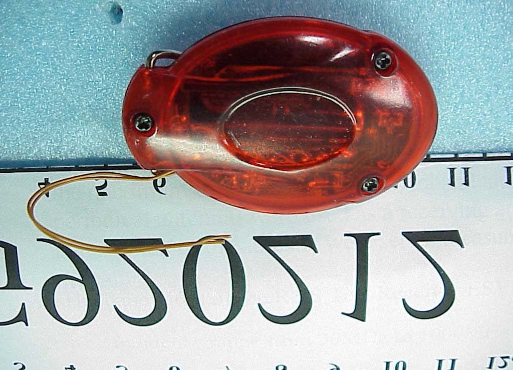
Click to zoom
Application Details
- Equipment Class
- DSC - Part 15 Security/Remote Control Transmitter
- Date of Grant
- Mar 12, 2003
- Application Purpose
- Original Equipment
- Date of Application
- Mar 12, 2003
- Equipment Note
- Remote Reply Transmitter
- Frequency Range
- 433.00000000 - 433.00000000
- Company
- Dynamco Pty. Ltd.
- Country
- Australia
Documents & Files
Document Text
Text extracted from the exhibit documents filed with the FCC. Open a document above to read the original.
Users Manual
FCC ID. PJ9TX22 Page 1 of 2 FCC ID. PJ9TX22 CAUTION: To assure continued FCC compliance: Any changes or modifications not expressly approved by the grantee of this device could void the user's authority to operate the equipment. FCC Label Compliance Statement: This device complies with Part 15 of the FCC Rules. Operation is subject to he following two conditions: (1) this device may not cause harmful interference, and (2) this device must accept any interference received, including interference that may cause undesired operation. Page 2 of 2
Block Diagram
Page 11 Dynamco Pty. Ltd. Remote Relay (Transmitter) FCC ID. : PJ9TX22 Block Diagram [NOTE]: (1). These buttons are normally open (i.e. spring loaded to remain open and only close when pushing) (2). There is no latching circuit to lock on transmitter after initial button is pushed.
Cover Letter(s)
From: shelene Sent: Thursday, March 13, 2003 12:08 AM To: Mike Kuo; 'leon' Subject: Re: Dynamco Pty. Ltd., FCC ID:PJ9TX22, AN03T2650 Dear Mike : Attached please find the revised manual, waiting for your grant letter soon ! Shelene ----- Original Message ----- From: "Mike Kuo" <[email protected]> To: "'leon'" Cc: "1Shelene Hou(TTEMC)" Sent: Thursday, March 13, 2003 3:39 PM Subject: RE: Dynamco Pty. Ltd., FCC ID:PJ9TX22, AN03T2650 > Hi Leon : > > The attached file is user manual. I will use the other file that you > submitted as operational description. However, if the attached file is user > manual, the information required under section 15.21 and 15.19(a)(3) of FCC > rules have to be included in the user manual. Please provide revised user > manual to include the statement. > > Best Regards > > Mike Kuo > Compliance Certification Services > 561F Monterey Road > Morgan Hill, CA 95037 > Tel: (408)463-0885 x:105 > Fax:(408)463-0888 > e-mail:[email protected] > > > -----Original Message----- > From: leon > Sent: Tuesday, March 11, 2003 6:05 PM > To: Mike Kuo > Cc: 1Shelene Hou(TTEMC) > Subject: Re: Dynamco Pty. Ltd., FCC ID:PJ9TX22, AN03T2650 > > > Hello Mike: > Question 1:The wire was used to short SW to keep on transmitting during > whole test. > (Do we need provide the photo without wire?) Question > 2:Please see the attached file that my client has just one to provide. > Please advise if any. Best regards. Leon 3/12 Audix EMC > > > > > > > > -----Original Message----- > > > From: CERTADM > > > Sent: Tuesday, March 11, 2003 11:41 AM > > > To: '[email protected]' > > > Subject: Dynamco Pty. Ltd., FCC ID:PJ9TX22, AN03T2650 > > > > > > > > > Notice_content > > > ------------- > > > Question #1: As indicated in the internal photos, there are two > > > external wires are connected to PCB. Please explain the purpose of > > > these > external > > > wires. > > > > > > Question #2: Please provide operational description. Please note: > > > User manual is not equal to operational description. > > > > > > Best Regards > > > > > > > > > Mike Kuo > > > The items indicated above must be submitted before processing can > continue > > > on the above referenced application. Failure to provide the > > > requested information within 60 days of the original e-mail date may > > > result in application dismissal and forfeiture of the filing fee. > > > Also, please > note > > > that partial responses increase processing time and should not be > > submitted. > > > Any questions about the content of this correspondence should be > directed > > to > > > the e-mail address listed below the name of the sender. > > > > > > > >
External Photos
Page 6 Dynamco Pty. Ltd. Remote Relay (Transmitter) FCC ID. : PJ9TX22 Photographs Photos 1 General Appearance (Front View) Photos 2 General Appearance (Rear View)
ID Label/Location Info
Page 4 Dynamco Pty. Ltd. Remote Relay (Transmitter) FCC ID. : PJ9TX22 Label Drawing z Label Placement Location (Bottom Side of EUT) FCC LABEL 20mm FCC ID : PJ9TX22 10mm
Internal Photos
Page 7 Dynamco Pty. Ltd. Remote Relay (Transmitter) FCC ID. : PJ9TX22 Photos 3 Internal View (Removed Case) Photos 4 PCB View (Component Side) Page 8 Dynamco Pty. Ltd. Remote Relay (Transmitter) FCC ID. : PJ9TX22 Photos 5 PCB View (Solder Side)
Operational Description
FCC ID. PJ9TX22 CAUTION: To assure continued FCC compliance: Any changes or modifications not expressly approved by the grantee of this device could void the user's authority to operate the equipment. FCC Label Compliance Statement: This device complies with Part 15 of the FCC Rules. Operation is subject to he following two conditions: (1) this device may not cause harmful interference, and (2) this device must accept any interference received, including interference that may cause undesired operation.
Schematics
Page 12 Dynamco Pty. Ltd. Remote Relay (Transmitter) FCC ID. : PJ9TX22 Schematics Diagram
Test Report
FCC ID.PJ9TX22 Page 1 of 21 APPLICATION FOR CERTIFICATION On Behalf of Dynamco Pty. Ltd. Remote Relay (Transmitter) Model : TX22 FCC ID:PJ9TX22 Prepared for : Dynamco Pty. Ltd. 10 Brown Street, East Perth, Western Australia 6004 Australia Prepared by : Audix Corporation No. 53-11, Tin-Fu Tsun, Lin-Kou, Taipei Hsien, Taiwan, R.O.C. Tel : (02) 2609-9301, 2609-2133 Fax: (02) 2609-9303 File Number : ATM-G920212 Report Number : TTEMC-F92042 Date of Test : Mar. 08 ~ 09, 2003 Date of Report : Mar. 10, 2003 Audix Corporation Report No.: TTEMC-F92042 FCC ID.PJ9TX22 Page 2 of 21 TABLE OF CONTENTS Description Page TEST REPORT CERTIFICATION.......................................................................................................3 1. GENERAL INFORMATION..........................................................................................................4 1.1. Description of Device (EUT).............................................................................................................4 1.2. Description of Test Facility ................................................................................................................5 1.3. Measurement Uncertainty..................................................................................................................5 2. POWERLINE CONDUCTED TEST..............................................................................................6 3. RADIATED EMISSION TEST.......................................................................................................7 3.1. Test Equipment...................................................................................................................................7 3.2. Test Setup...........................................................................................................................................7 3.3. Radiation Limit (§15.231)..................................................................................................................8 3.4. EUT’s Configuration during Compliance Measurement....................................................................8 3.5. Operating Condition of EUT ..............................................................................................................8 3.6. Test Procedure....................................................................................................................................9 3.7. Radiated Emission Noise Measurement Results..............................................................................10 4. EMISSION BANDWIDTH TEST................................................................................................13 4.1. Test Equipment.................................................................................................................................13 4.2. Block Diagram of Test Setup...........................................................................................................13 4.3. Specification Limits (§15.231-(c))...................................................................................................13 4.4. EUT’s Configuration during Compliance Measurement..................................................................13 4.5. Emission Bandwidth Measurement Results.....................................................................................13 5. PERIODIC OPERATED TEST.....................................................................................................15 5.1. Test Equipment.................................................................................................................................15 5.2. Block Diagram of Test Setup...........................................................................................................15 5.3. Specification Limits [§15.231-(a)-(1)].............................................................................................15 5.4. EUT’s Configuration during Compliance Measurement..................................................................15 5.5. Periodic Operated Measurement Results..........................................................................................15 6. DEVIATION TO TEST SPECIFICATIONS................................................................................17 7. PHOTOGRAPHS..........................................................................................................................18 7.1. Photos of Radiated Measurement at Semi-Anechoic Chamber (30~1000MHz) ............................18 7.2. Photos of Radiated Measurement at Semi-Anechoic Chamber (1~5GHz) .....................................19 7.3. Photos of Emission Bandwidth Measurement..................................................................................21 7.4. Photos of Periodic Operated Measurement......................................................................................21 Audix Corporation Report No.: TTEMC-F92042 FCC ID.PJ9TX22 Page 3 of 21 TEST REPORT CERTIFICATION Applicant : Dynamco Pty. Ltd. Manufacturer : Tesor Plus Corp. EUT Description : Remote Relay (Transmitter) FCC ID : PJ9TX22 (A) MODEL NO. : TX22 (B) SERIAL NO. : N/A (C) POWER SUPPLY:DC 12V Measurement Procedure Used: FCC RULES AND REGULATIONS PART 15 SUBPART C, MAY 2002 AND ANSI C63.4/1992 (FCC CFR 47 Part 15C, §15.207 and §15.231) The device described above was tested by AUDIX COPORATION. to determine the maximum emission levels emanating from the device. The maximum emission levels were compared to the FCC Part 15 subpart C limits both radiated and conducted emissions. The measurement results are contained in this test report and AUDIX CORPORATION. is assumed full responsibility for the accuracy and completeness of these measurements. Also, this report shows that the EUT to be technically compliant with the FCC official limits. This report applies to above tested sample only. This report shall not be reproduced in part without written approval of Audix Cor…
Text truncated - open the document above for the full version.
Test Setup Photos
FCC ID.PJ9TX22 Page 18 of 21 7. PHOTOGRAPHS 7.1. Photos of Radiated Measurement at Semi-Anechoic Chamber(30~1000MHz) EUT on Stand EUT on Side Audix Corporation Report No.: TTEMC-F92042 FCC ID.PJ9TX22 Page 19 of 21 EUT on Lie 7.2. Photos of Radiated Measurement at Semi-Anechoic Chamber (1~5GHz) EUT on Stand Audix Corporation Report No.: TTEMC-F92042 FCC ID.PJ9TX22 Page 20 of 21 EUT on Side EUT on Lie Audix Corporation Report No.: TTEMC-F92042 FCC ID.PJ9TX22 Page 21 of 21 7.3. Photos of Emission Bandwidth Measurement 7.4. Photos of Periodic Operated Measurement Audix Corporation Report No.: TTEMC-F92042
Contact Information
Applicant
Richard Frizell(Director)
Test Firm
Audix Technology CorporationJeff Chen
Technical Specifications
| # | Rule Parts | Frequency Range | Power Output |
|---|---|---|---|
| 1 | 15.231 | 433 MHz - 433 MHz | - |
Other Applications from Dynamco Pty. Ltd.

PJ9DX5-900
Jul 06, 2010TX-90M-900
Equipment Class
DXX - Part 15 Low Power Communication Device Transmitter
PJ9TX90M-900
Jul 04, 2010TX-90M-900
Equipment Class
DXX - Part 15 Low Power Communication Device Transmitter
PJ9PIR-900
Jul 04, 2010PIR-900
Equipment Class
DXX - Part 15 Low Power Communication Device Transmitter
PJ9TOOLBOX-SEN900
Jul 04, 2010TOOLBOX-SEN-900
Equipment Class
DXX - Part 15 Low Power Communication Device Transmitter
PJ9TX21
Jul 30, 2006Remote Relay (Transmitter)
Equipment Class
DSC - Part 15 Security/Remote Control Transmitter