PJV-RX02Electronic Pen and Laser Pointer
Hitachi Solutions, Ltd.
Click to zoom
Application Details
- Equipment Class
- DXX - Part 15 Low Power Communication Device Transmitter
- Date of Grant
- Feb 19, 2002
- Application Purpose
- Original Equipment
- Date of Application
- Feb 19, 2002
- Equipment Note
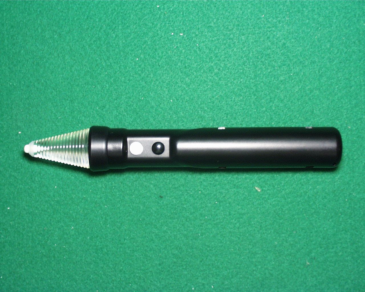
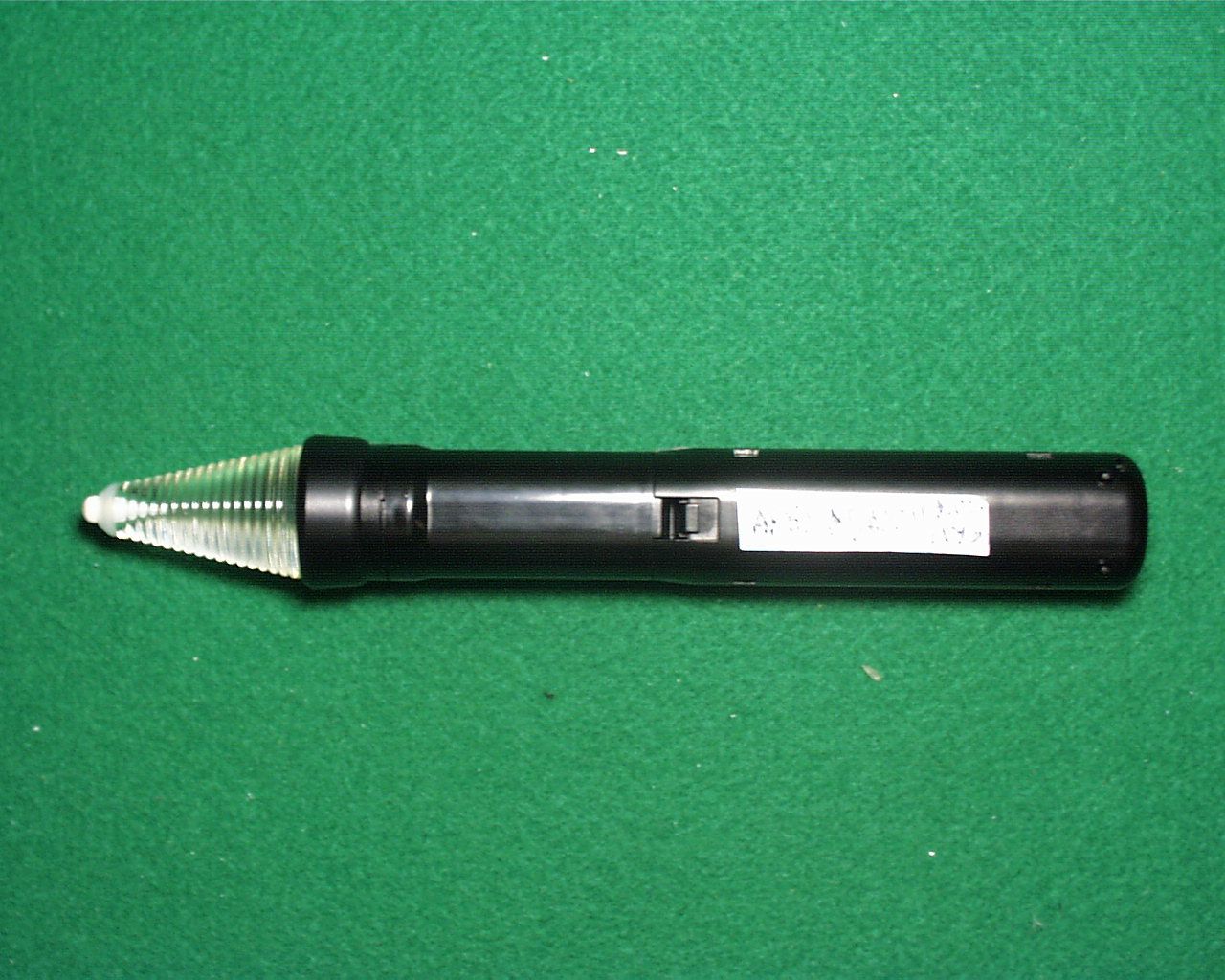
- Electronic Pen and Laser Pointer
- Frequency Range
- 911.10000000 - 911.70000000
- Company
- Hitachi Solutions, Ltd.
- Country
- Japan
Documents & Files
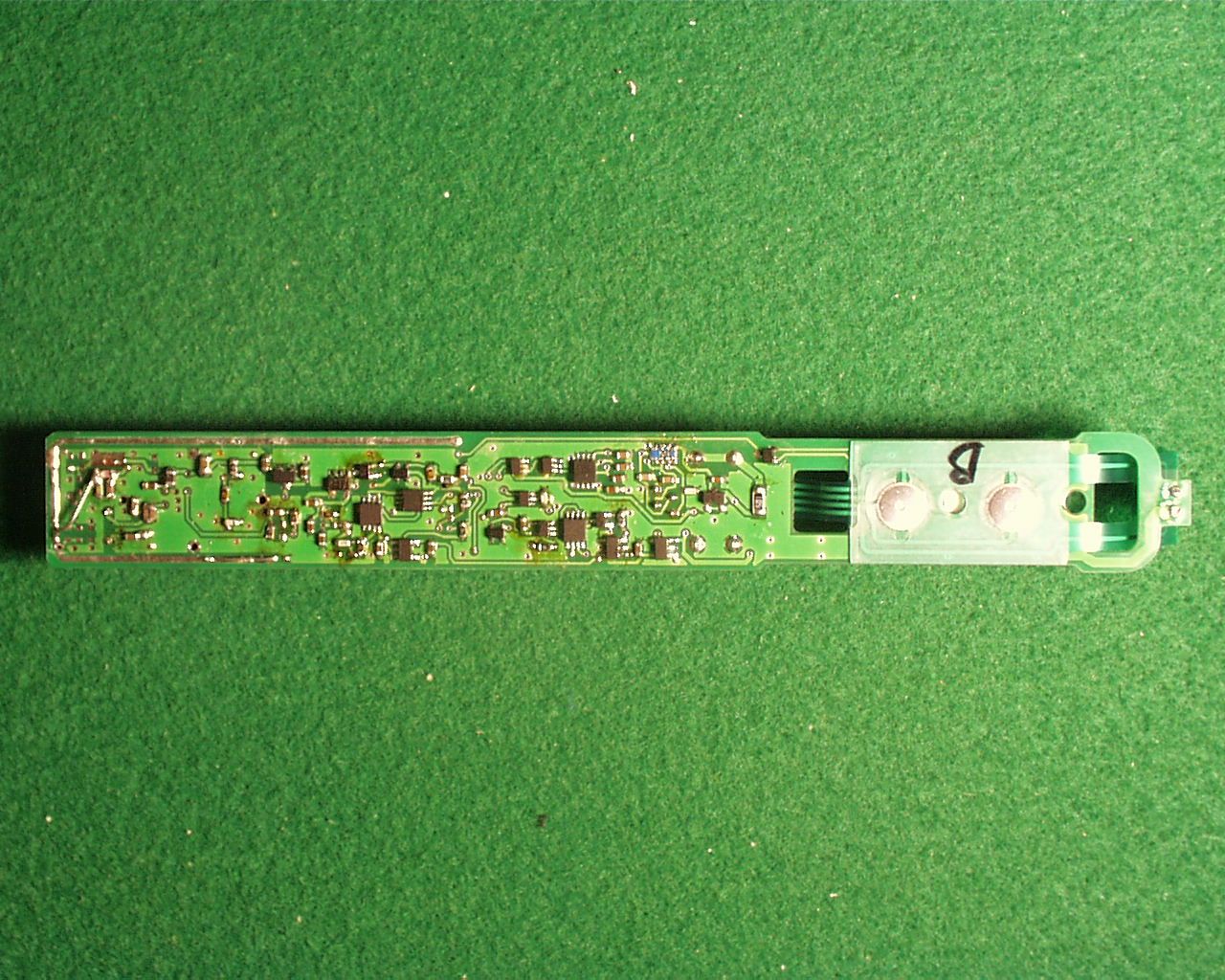
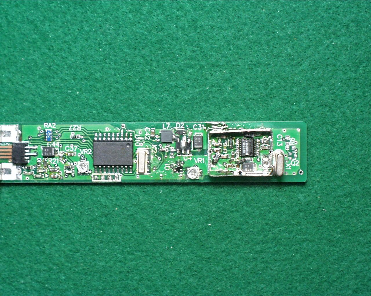
Document Text
Text extracted from the exhibit documents filed with the FCC. Open a document above to read the original.
Users Manual
StarBoard R-70X User's Guide Manual request To request this manual separately, specify T225-2-001-10(E). Read this manual thoroughly and store it carefully. Before using this product, read the safety explanations and understand them well. Keep this manual on hand so that the user can refer to it at any time. T225-2-001-10(E) Hitachi Software Engineering Co., Ltd. i Cautions No part of this manual may be reproduced in any form without permission. The contents of this manual may be altered without prior notice. This manual is documented, making assurance doubly sure. If there are questions, e.g., obscure or erroneous portions, contact your sales shop. We do not take responsibility for damage caused as a result of operating this product regardless of the items above. LASER SEFETY This device uses an infrared laser. It has been certified and found to comply with the specifications for a Class I laser device of Japanese Industrial Standards JIS C 6802 and Title 21, USA code of Federal Regulations, Subchapter J, of FDA rules. This means that this device is classified to produce the weakest level of laser radiation. It also means the device is safe for normal use, but please observe the instructions listed under “For safe operation and handling” to ensure safe use of the product. NOTICE This equipment has been tested and found to comply with the limits for a Class A digital device, pursuant to part 15 of the FCC Rules. These limits are designed to provide reasonable protection against harmful interference when the equipment is operated in a commercial environment. This equipment generates, uses, and can radiate radio frequency energy and, if not installed and used in accordance with the instruction manual, may cause harmful interference to radio communications. Operation of this equipment in a residential area is likely to cause harmful interference, in which case the user will be required to correct the interference at his own expense. FCC Warning The user is cautioned that changes and modifications made to the equipment without approval of the manufacturer could void the user's authority to operate this equipment. CLASS I LASER PRODUCT FCC ID: PJV-RX02 This device complies with Part 15 of the FCC Rules. Operation is subject to the following two conditions: (1) this device may not cause harmful interference, and (2) this device must accept any interference received, including interference that may cause undesired operation. PRODUIT LASER DE CLASSE 1 ii Warning This is a class A productIn a domestic environment this product may cause radio interference in which case the user may be required to take adequate measures The R&TTE Directive We, the manufacturer (Hitachi Software Engineering Co., Ltd.) hereby declare that this equipment (digitizer), model K-W019-005 is in compliance with the essential requirements and other relevant provisions of Directive 1999/5/EC. Nous, le fabriquant (Hitachi Software Engineering Co., Ltd.) déclarons par le présent document que l’équipement (digitaliseur), modèle K-W019-005 est conforme avec l’ensemble des pré requis des directives 1999/5/EC. Hiermit erklären wir, der Hersteller (Hitachi Software Engineering Co., Ltd.), daß dieses Gerät (Digitizer), Modell K-W019-005 germäß den wensentlichen Erfordernissen und anderen relevanten Vorschriften von Directive 1999/5/EC ist. Wij, de fabrikant (Hitachi Software Engineering Co., Ltd.) verklaren hierbij dat deze apparatuur (digitizer), model K-W019-005 voldoet aan de essentiële vereisten en andere relevante bepalingen van de Richtlijn 1999/5/EC. Industry Canada: ICES-003 iii ü This class A digital apparatus complies with Canadian ICES-003. ü Cet appareil numérique de la classe A est conforme à la norme NMB- 003 du Canada. Industry Canada: RSS-210 Operation is subject to the following two conditions; (1)this device may not cause interference, and (2) this device must accept any interference, including interference that may cause undesired operation of the device.” Subcarrier frequency for EU CH1 869.720 MHz CH4 869.980 MHz for USA or Canada CH1 911.1 MHz CH4 911.7 MHz RF output power 200 W (at 50[ ]) This device has been designed to operate with an antenna having a maximum gain of -1 dB. Antenna having a higher gain is strictly prohibited per regulations of Industry Canada. The Required antenna impedance is 50 ohms.” To reduce potential radio interference to other users, the antenna type and its gain should be so chosen that the equivalent isotropically radiated power (EIRP) is not more than that required for successful communication.” The term "IC:" before the radio certification number only signifies that Industry Canada technical specifications were met. iv Exemption Clauses Hitachi Software Engineering Co., Ltd. does not take responsibility for or guarantee the contents described in this user's guide explicitly and implicitly. Especially, it never assures the guarantee, product validity, and adaptability for a specific usage. All software products of Hitachi Software Engineering Co., Ltd. described in this user's guide must be sold and used as they are. Purchasers of these software products (excluding Hitachi Software Engineering Co., Ltd., its agencies, and sales shops) must bear the cost of all servicing (required to recover defects in these software products), repair, and unexpected or necessary damage. They must also bear the cost of unexpected or necessary damage caused by hardware defects, and extensive damage. In view of these contents, Hitachi Software Engineering Co., Ltd. may revise this user's guide and alter its contents without notice. Product Guarantee The contents of the guaranteed are explained in Appendix H at the end of this user's guide. This manual is issued as the second edition (T225-2-001-10(E))for the following products. K-W019-005 (R-70X digitizer) K-W019-002 (R-70X stand K-W019-301 (R-70X electronic pen K-W019-103 (LC rear projector: manufactured by Hitachi Limited.: NX70- 1111S-DBW) Windows i…
Text truncated - open the document above for the full version.
Operational Description
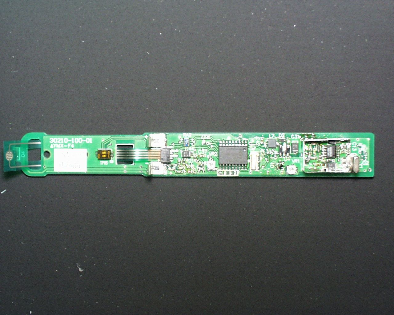
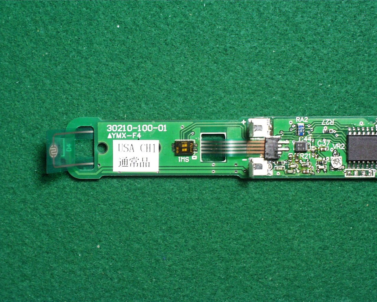
Shiba Denshi Confidential 1 PC- AT Com patibl e m achine Vi deo cable LD PW BA SOS MPA LD PW BA SOS MPA AC cabl e Seri al cabl e +24V Pen dow n lef t cli ck Right cl ick Doubl e cl i ck P hoto detector Si gnal processi ng ci rcui t • RFTransm i tting part (PW BA PEN ) m em brane sw i tch E lectronic pen A l aser concentrate l igh t PW BA MAIN LVPS +24V 2. 2A INLET 70 i nch back proj ecti on crystal di spl ay or 61 i nch col or pl asm a di spl ay Uni t L eft U n i t R i ght Battery charger COUPLER TX AN T RX ANT Battery ‡@ ‡@ ‡A ‡A ‡B ‡C PW BA RF ‡D Shiba Denshi Confidential 2 This device detects a position(X,Y) of the electronic pen using two laser scanner units. PWBA MAIN calculates a position(X,Y) of the electronic pen by triangulation method. Detail is shown as follows: First, time interval is measured from the time scanning laser has passed SOS to the time it has arrived at the sensor of pen for each laser scanner unit. Next, the angle is taken by the above time interval for each unit. Finaly, the pen position is obtained from each angle by triangulation method. Unit Right is consists of PWBA RF, PWBA MAIN and LSU. Unit Left is consists of LVPS and LSU. LSU is consists of PWBA LD, MPA and SOS. Electronic pen is consists of sensor,Pen Down S/W, and Pen side S/W. • PW BA LD •A laser irradiated with PWBA LD is scanned by MPA(Motor Plygon Assy). • SOS •Signal of start of scan is sent from SOS to PWBA MAIN. • electronic pen •An electronic pen transmits the inside information (Photo detector, Pen down S/W, •Pen side S/W ) by an radio waves through TX ANT. • PW BA RF •PWBA RF demodulates a signal through the RX ANT. and the coupler in an electronic pen, •and send to PW BA MAI N. • PW BA MAI N •PWBA MAIN transmits position informations of an elctronic pen to PC-AT compatible machine.
Test Report
Test report No.: 22EE0006-YW-2 Page: 2 of 20 Issued date: February 4, 2002 FCC ID: PJV-RX02 A-pex International Co., Ltd. YOKOWA LAB. 108 Yokowa-cho, Ise-shi, Mie-ken 516-1106 JAPAN Telephone:int +81 596 39 1485 Facsimile: int +81 596 39 0232 CONTENTS PAGE SECTION 1: Client information 3 SECTION 2: Equipment under test (E.U.T.)3 SECTION 3: Test specification, methods & procedures4 SECTION 4: Operation of E.U.T. during testing5 SECTION 5: Summary of test results 6 SECTION 6: Radiated emission7 APPENDIX 1: Photographs of test setup8 APPENDIX 2:Test instruments8 APPENDIX 3: Data of EMI test8 Test report No.: 22EE0006-YW-2 Page: 3 of 20 Issued date: February 4, 2002 FCC ID: PJV-RX02 A-pex International Co., Ltd. YOKOWA LAB. 108 Yokowa-cho, Ise-shi, Mie-ken 516-1106 JAPAN Telephone:int +81 596 39 1485 Facsimile: int +81 596 39 0232 SECTION 1: Client information Company Name: Hitachi Software Engineering Co., Ltd. Company Trade Name: Hitachi Software Engineering Co., Ltd. Address: 6-81 Onoe-cho, Naka-ku,Yokohama-shi, Kanagawa 231-0015 Japan Telephone Number: +81-45-681-2146 Facsimile Number: +81-45-681-3062 Contact Person : Yasuhiro Nakada SECTION 2: Equipment under test (E.U.T.) 2.1Identification of E.U.T. Type of Equipment: Electronic Pen Model No.: K-W019-301 FCC ID: PJV-RX02 Condition of EUT: Production Prototype Rating: DC 2.4V Country of Manufacture: Japan Receipt Date of Sample: January 8, 2002 2.2Product Description Model: K-W019-301, referred to as the EUT in this report, is an Electronic Pen. This product is supplied to Hitachi Software Engineering as a unit. By combining with a large-sized back projection display, an electronic pen is made into an input device and it is located as a product, which has digitizer ability. Clock frequency is as follows; CPU : 2MHz The specification is as follows; Carrier Frequency: 911.1MHz and 911.7MHz Operation Voltage: DC2.4V (Ni-MH) Modulation: Frequency Modulation Information on antenna : Build in antenna Test report No.: 22EE0006-YW-2 Page: 4 of 20 Issued date: February 4, 2002 FCC ID: PJV-RX02 A-pex International Co., Ltd. YOKOWA LAB. 108 Yokowa-cho, Ise-shi, Mie-ken 516-1106 JAPAN Telephone:int +81 596 39 1485 Facsimile: int +81 596 39 0232 SECTION 3: Test specification, methods & procedures 3. 1Test Specification Test Specification : FCC Part 15 Subpart C Title: FCC 47CFR Part15 Radio Frequency Device Subpart C Intentional Radiators §15.249 Operation within the Band 902-928MHz, 2400-2483.5MHz, 5725-5875MHz and 24.0-24.25GHz 3.2Methods & Procedures No.ItemTest ProcedureSpecificationRemarks 1Electric Field Strength of Fundamental Emission FCC/ANSI C63.4:1992§15.249(a)3m 2Electric Field Strength of Spurious Emission FCC/ANSI C63.4:1992§15.249(a), (c)3m 3.3 Additions or deviations to standards No addition, deviation or exclusion has been made from standards. Test report No.: 22EE0006-YW-2 Page: 5 of 20 Issued date: February 4, 2002 FCC ID: PJV-RX02 A-pex International Co., Ltd. YOKOWA LAB. 108 Yokowa-cho, Ise-shi, Mie-ken 516-1106 JAPAN Telephone:int +81 596 39 1485 Facsimile: int +81 596 39 0232 SECTION 4: Operation of E.U.T. during testing 4.1Operating Modes The EUT exercise program used during radiated and conducted testing was designed to exercise the various system components in a manner similar to typical use. The operating mode/system were as follows: The sequence is used: Transmitting mode (Ch1:911.1MHz and Ch4:911.7MHz) Justification: The system was configured in typical fashion (as a customer would normally use it) for testing. 4.2 Configuration and peripherals Front View (Horizontal) A:EUT Front View (Vertical) A:EUT *Test data was taken under worse case conditions. Description of EUT and Support equipment No.ItemModel numberSerial numberManufacturerFCC IDRemark AElectronic PenK-W019-301 (911.1MHz or 911.7MHz) -Suzuka Fuji XeroxPJV-RX02EUT Test report No.: 22EE0006-YW-2 Page: 6 of 20 Issued date: February 4, 2002 FCC ID: PJV-RX02 A-pex International Co., Ltd. YOKOWA LAB. 108 Yokowa-cho, Ise-shi, Mie-ken 516-1106 JAPAN Telephone:int +81 596 39 1485 Facsimile: int +81 596 39 0232 SECTION 5: Summary of test results 5.1Test results No.ItemTest ProcedureSpecificationWorst marginResult Ch1:911.1MHz 13.9dB, HOR (EUT: Horizontal) 1Electric Field Strength of Fundamental Emission ANSI C63.4:1992§15.249(a) Ch4:911.7MHz 9.9dB, HOR (EUT: Horizontal) Complied Ch1:911.1MHz PK=18.3dB (1822.20MHz,HOR) (EUT: Horizontal) AV=1.5dB (1822.20MHz, VER) (EUT: Vertical) 2Electric Field Strength of Spurious Emission ANSI C63.4:1992§15.249(a), (c) Ch4:911.7MHz PK=21.5dB (9117.00MHz, VER) (EUT: Horizontal) AV=3.6dB (1823.40MHz, HOR) (EUT: Horizontal) Complied A-PEX INTERNATIONAL hereby confirms that E.U.T., in the configuration tested, complies with the specifications FCC Part 15 Subpart C §15.249. 5.2Uncertainty Radiated Emission Test The measurement uncertainty (with a 95% confidence level) for this test using Biconical antenna is ±4.4dB. The measurement uncertainty (with a 95% confidence level) for this test using Logperiodic antenna is ±4.8dB. The data listed in this test report may exceed the test limit because it does not have enough margin. 5.3Test Location A-PEX International Co.,Ltd. Yokowa No.3 test site 108 Yokowa-cho, Ise-shi, Mie-ken 516-1106 Japan Telephone number: +81-596-39-1485 Facsimile number: +81-596-39-0232 This site has been fully described in a report submitted to FCC office, and listed on September 12, 2000 (Registration number: 90412), and they were accepted by Industry Canada on May 1, 2001 (Registration number: IC2973-3). *NVLAP Lab. code : 200109-0 5.4Photographs of test setup Refer to Appendix 1. 5.5Test instruments Refer to Appendix 2. 5.6Data of EMI Test Refer to Appendix 3. Test report No.: 22EE0006-YW-2 Page: 7 of 20 Issued date: February 4, 2002 FCC ID: PJV-RX02 A-pex International Co., Ltd. YOKOWA LAB. 108 Yokowa-cho, Ise-shi, Mie-ken 516-1106 JAPAN Telephone:int +81 596 39 1485 Facsimile: int +81 596 39 0232 SECTION 6: Radiated e…
Text truncated - open the document above for the full version.
Test Setup Photos
Test report No.: 22EE0006-YW-2 Page: 9 of 20 Issued date: February 4, 2002 FCC ID: PJV-RX02 A-pex International Co., Ltd. YOKOWA LAB. 108 Yokowa-cho, Ise-shi, Mie-ken 516-1106 JAPAN Telephone:int +81 596 39 1485 Facsimile: int +81 596 39 0232 Radiated emission Horizontal Vertical
Contact Information
Applicant
Shigeru Kano
Technical Contact
A-Pex International Co. ,Ltd.Naoki Sakamoto
[email protected]+81 596 39 1485
108 Yokowa-cho · Ise-Shi, Mie-ken · Japan
Test Firm
UL Japan, Inc.Kazunori Nishimura
Technical Specifications
| # | Rule Parts | Frequency Range | Power Output |
|---|---|---|---|
| 1 | 15C | 911.1 MHz - 911.7 MHz | - |
Other Applications from Hitachi Solutions, Ltd.

PJV-VTE102
Apr 03, 2012USB Receiver
Equipment Class
DXX - Part 15 Low Power Communication Device Transmitter
PJV-VTE101
Apr 03, 2012Interactive Voting System
Equipment Class
DXX - Part 15 Low Power Communication Device Transmitter