PKG07188RC27Radio Toy Controller
May Cheong Toy Products Fty. Ltd.Application Details
- Equipment Class
- DXX - Part 15 Low Power Communication Device Transmitter
- Date of Grant
- Jan 09, 2008
- Application Purpose
- Original Equipment
- Date of Application
- Jan 09, 2008
- Equipment Note
- Radio Toy Controller
- Frequency Range
- 27.14500000 - 27.14500000
- Country
- Hong Kong
Documents & Files
Document Text
Text extracted from the exhibit documents filed with the FCC. Open a document above to read the original.
Users Manual
The packaging has to be kept since it contains important information. Contents: Project 66 x 1 Transmitter x 1 Transmitter antenna x 1 Instruction Manual x 1 Project 66: Installation of Batteries 1. Switch the power OFF. 2. Open the battery cover using a screwdrive. 4. Transmitter: Battery and Antenna Installation 1. Switch the power OFF. 2. Open the battery cover. 4. Close the battery cover. 5. Screw the antenna into the transmitter securely. How to play: 1. Fully extend the antenna of the transmitter. 2. Match the transmitter with the Project 66 Channel (Channel A or B or C). 3. Switch ON the transmitter, the transformation button will light up. 4. Switch ON the Project 66. 5. Use the transimitter's levers and buttons to control the movement, transformation and shooting of Project 66 A. Movement i. Push the left / right lever up or down to move the Project 66. Maisto Radio Control Project 66 Take out the battery compartment and install six new 1.5V AA batteries with correct polarity (+/-) as shown inside the battery copartment. Insert the battery compartment back and fastern the battery cover. Install a new 9V battery with correct polarity (+/-) as shown inside the battery compartment. ! Warning!Do not aim at eyes or face Warning! There are hazardous of using projectiles other than those supplied or recommended by the manufacturer. 3. 3. B. Transformation i. Press the transform button to transform Project 66 into different mode. C. Shooting i. Transform into attack mode and Insert 5 missiles into the launcher. ii. Press the shoot button to shoot missiles one by one. Performance Tips: 1. Do not drive on grass, sand, carpet or go through water. 2. Do not drive in windy or rainy weather. 3. Avoid colliding with hard surfaces. 4. Switch OFF the Project 66 and transmitter when not in use. 5. Remove all batteries from the Project 66 and transmitter when not in use. 6. Fully extend the antenna for best performance and do not point the antenna toward the Project 66. 7. The operating range can be affected by a variety of factors: a) Weak transmitter battery, or under-charged batteries. 8. Make sure all missiles insert into the launcher tightly. 9. Check if there is foreign object inside the Project 66 before transformation each time. Cautions : 1. Do not aim at eyes or face. 2. Do not use projectiles other than those supplied or recommended by the manufacturer. 3. Do not pick up the Project 66 while its in motion. 4. Do not pick up the Project 66 by holding the wind shield or the rear wing. 5. Do not hold the wheels while the Project 66 is moving. 6. Do not bend the wind shield, body and missiles of the Project 66. 7. Do not force to pull missiles out from launcher. 8. Keep fingers, hair and loose clothing away from the wheels. Battery use : 1. Alkaline batteries are recommended to use. 2. Only batteries of the same or equivalent type as recommended are to be used. 3. Do not mix alkaline, standard or rechargeable batteries. 4. Do not mix old and new batteries or different type of batteries. 5. Non-rechargeable batteries are not to be charged. 6. If rechargeable batteries are used, they are only to be charged under adult supervision. 7. Rechargeable batteries are to be removed from the product before they are charged. 8. Be sure to insert batteries with the correct polarities and always follow the battery manufacturer's instructions. 9. Remove all batteries from the vehicle and transmitter when not in use. 10. Exhausted batteries are to be removed from the product. 11. The supply terminals are not to be short-circuited. 12. Dispose of batteries properly. Do not dispose the batteries in fire — it may cause them to explode or leak causing injury or damage FCC Label Compliance Statement: This device complies with part 15 of the FCC rules. Operation is subject to the following two conditions : 1. b) Interference from other items that emit radio frequency signals such as another R/C item on the same frequency, CB radios, cordless phones, high voltage transformers, etc. This device may not cause harmful interference, and 2. RSS-310 Compliance Statement : This radiocommunication device complies with all the requirements of Industry Canada Standard RSS-310. FAQ (Frequently Asked Questions) 1) Why does my Project 66 not start? Make sure the transmitter and the vehicle are turned on. Check to make sure the batteries are not drained. Make sure the batteries are installed per polarity indicators. Make sure all 4 wheels are not obstructed by any foreign objects. 2) Why does my Project 66 make unusual noises? Check to make sure the batteries are not drained. Check to make sure all 4 wheels are not obstructed by any foreign objects. Check to make sure no foreign object inside Project 66. Operation is subject to the following two conditions: (1) this device may not cause interference, and (2) this device must accept any interference, including interference that may cause undesired operation of the device. This device must accept any interference received, including interference that may cause undesi r operation. Note : This equipment has been tested and found to comply with the limits for a Class B digital device, pursuant to Part 15 of the FCC Rules. These limits are designed to provide reasonable protection against harmful interference in a residential installation. This equipment generates, uses and can radiate radio frequency energy and, if not installed and used in accordance with the instructions, may cause harmful interference to radio communications. However, there is no guarantee that interference will not occur in a particular installation. If this equipment does cause harmful interference to radio or television reception, which can be determined by turning the equipment off and on, the user is encouraged to try to correct the interference by one or more of the following measures: - Reorient or relocate the receiving antenna. - Increase the separation between the equipment and receiver. - Connect the …
Text truncated - open the document above for the full version.
External Photos
Report No.SZEE071224113304 Page 14 of 15 7.APPENDIX 2 PHOTOGRAPHS OF EUT TOP VIEW OF SAMPLE BOTTOM VIEW OF SAMPLE
Internal Photos
Internal top photo of TX Internal bottom photo of TX
Operational Description
Model:07188 27 MHZ Operation Description The U1 reads output commands and encodes .the codes are sent to RF oscillator, and then modulates 27MHZ carry frequency signal to achieve AM signal. The radio frequency of the transmitter is based on 27MHZ AM citizen's band. It generates low power 27.145MHZ carrier frequency via major components of Q1,X1 etc. Please note that the value of the component and see attached schematics for more detail. The AM signal(Via capacitor C7)is passed to the antenna(ANT) via regarding components.
Test Report
Report No.SZEE071224113304 Page 1 of 15 ELECTROMAGNETIC EMISSIONS COMPLIANCE REPORT INTENTIONAL RADIATOR CERTIFICATION TO FCC PART15C REQUIREMENT OF 20-07188 Remote control (27.145MHZTX) MODEL No.: 20-07188 BRAND NAME: N/A FCC ID:PKG07188RC27 REPORT NO.: SZEE071224113304 ISSUE DATE: December 28, 2007 Prepared for MAY CHEONG TOY PRODUCTS FTY LTD 12/F,EMPIRE CENTRE,68 MODY ROAD,TSIMSHATSUI EAST,KOWLOON,HONGKONG TEL: 86-769-8775 3128 FAX: 86-769-8775 3123 Prepared by CENTRE TESTING INTERNATIONAL 1F., BUILDING C,HONGWEI INDUSTRIAL ZONE, BAOAN 70 DISTRICT, SHENZHEN, CHINA TEL: 86-755-3368 3668 FAX: 86-755-3368 3385 This report shall not be reproduced, except in full, without the written approval of CENTRE TESTING INTERNATIONAL Report No.SZEE071224113304 Page 2 of 15 Report No.SZEE071224113304 Page 3 of 15 TABLE OF CONTENTS Description Page 1. GENERAL INFORMATION .................................................................................................. 4 1.1PRODUCT DESCRIPTION........................................................................................................................4 1.2TEST METHODOLOGY...........................................................................................................................4 1.3TEST FACILITY.....................................................................................................................................4 1.4 SPECIAL ACCESSORIES........................................................................................................................4 1.5 EQUIPMENT MODIFICATIONS..............................................................................................................4 2. SYSTEM TEST CONFIGURATION ..................................................................................... 5 2.1 EUT CONFIGURATION.........................................................................................................................5 2.2 EUT EXERCISE....................................................................................................................................5 2.3TEST PROCEDURE.................................................................................................................................5 2.4LIMITATION..........................................................................................................................................6 2.5CONFIGURATION OF TEST SETUP..........................................................................................................7 3. SUMMARY OF TEST RESULTS .......................................................................................... 7 4. DESCRIPTION OF TEST MODES ....................................................................................... 7 5. RADIATED EMISSION TEST ............................................................................................... 8 5.1MEASUREMENT PROCEDURE................................................................................................................8 5.2TEST SET-UP (BLOCK DIAGRAM OF CONFIGURATION) ......................................................................9 5.3MEASUREMENT EQUIPMENT USED: ...................................................................................................10 5.4FIELD STRENGTH CALCULATION.......................................................................................................10 5.5MEASUREMENT RESULT.....................................................................................................................11 6.APPENDIX 1 PHOTOGRAPHS OF SETUP ....................................................................... 13 7.APPENDIX 2 PHOTOGRAPHS OF EUT ............................................................................ 14 Report No.SZEE071224113304 Page 4 of 15 1. GENERAL INFORMATION 1.1 Product Description The TRANSMITTER. Model: 20-07188(referred to as the EUT in this report) The EUT is an short range, lower power, 20-07188 Remote control designed as an “ Input Device”. It is designed by way of utilizing the FSK modulation achieves the system operating. A major technical descriptions of EUT is described as following: A). Operation Frequency: 27.145 MHz ,Three channel(A,B,C). B). Modulation: FSK C). Antenna Designation: integral antenna (it can’t be moved during the test) D). Power Supply: DC 9.0 V by battery. 1.2 Test Methodology Both conducted and radiated testing were performed according to the procedures in ANSI C63.4 (2003). Radiated testing was performed at an antenna to EUT distance 3 meters. 1.3 Test Facility The 3m Semi-Anechoic chamber test site and conducted measurement facility used to collect the radiated data is located on the address: 1F.,Building C, Hongwei Industrial Zone 70District.,Baoan,Shenzhen,Guangdong,China . The Test Sites and the Line Conducted labs are constructed and calibrated to meet the FCC requirements in documents ANSI C63.4: 2003 requirements. The test site Registration Number:614926 1.4 Special Accessories Not available for this EUT intended for grant. 1.5 Equipment Modifications Not available for this EUT intended for grant. Report No.SZEE071224113304 Page 5 of 15 2. System Test Configuration 2.1 EUT Configuration The EUT configuration for testing is installed on RF field strength measurement to meet the Commissions requirement and operating in a manner which intends to maximize its emission characteristics in a continuous normal application. 2.2 EUT Exercise The Transmitter was operated in the normal operating mode. the TX frequency was fixed which was for the purpose of the measurements. 2.3 Test Procedure 2.3.1 Conducted Emissions (Not apply in the report) The EUT is a placed on as turn table which is 0.8 m above ground plane. According to the requirements in Section 13.1.4.1 of ANSI C63.4-2003.Conducted emissions from the EUT measured in the frequency range between 0.15 MHz and 30MHz using CISPR Quasi-Peak and average detector mode. 2.3.2 Radia…
Text truncated - open the document above for the full version.
Test Setup Photos
Report No.SZEE071224113304 Page 13 of 15 6.APPENDIX 1 PHOTOGRAPHS OF SETUP RADIATED EMISSION TEST SETUP
Contact Information
Applicant
Anson Wang(QA Manager)
Test Firm
Centre Testing InternationalHe Xiaojun
Technical Specifications
| # | Rule Parts | Frequency Range | Power Output |
|---|---|---|---|
| 1 | 15C | 27.145 MHz - 27.145 MHz | - |
Other Applications from May Cheong Toy Products Fty. Ltd.
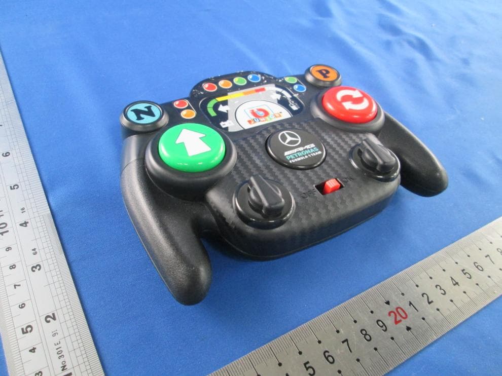
PKG25847RC
Jul 24, 2026MY FIRST FORMULA ASST(BB Junior - My First Formula RC - Mercedes-AMG)
Equipment Class
DXX - Part 15 Low Power Communication Device Transmitter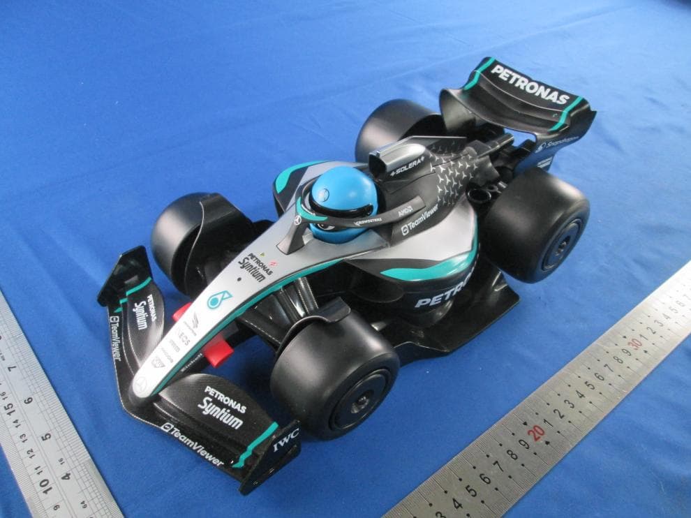
PKG91009RC
Jul 24, 2026MY FIRST FORMULA ASST(BB Junior - My First Formula RC - Mercedes-AMG)
Equipment Class
DXX - Part 15 Low Power Communication Device Transmitter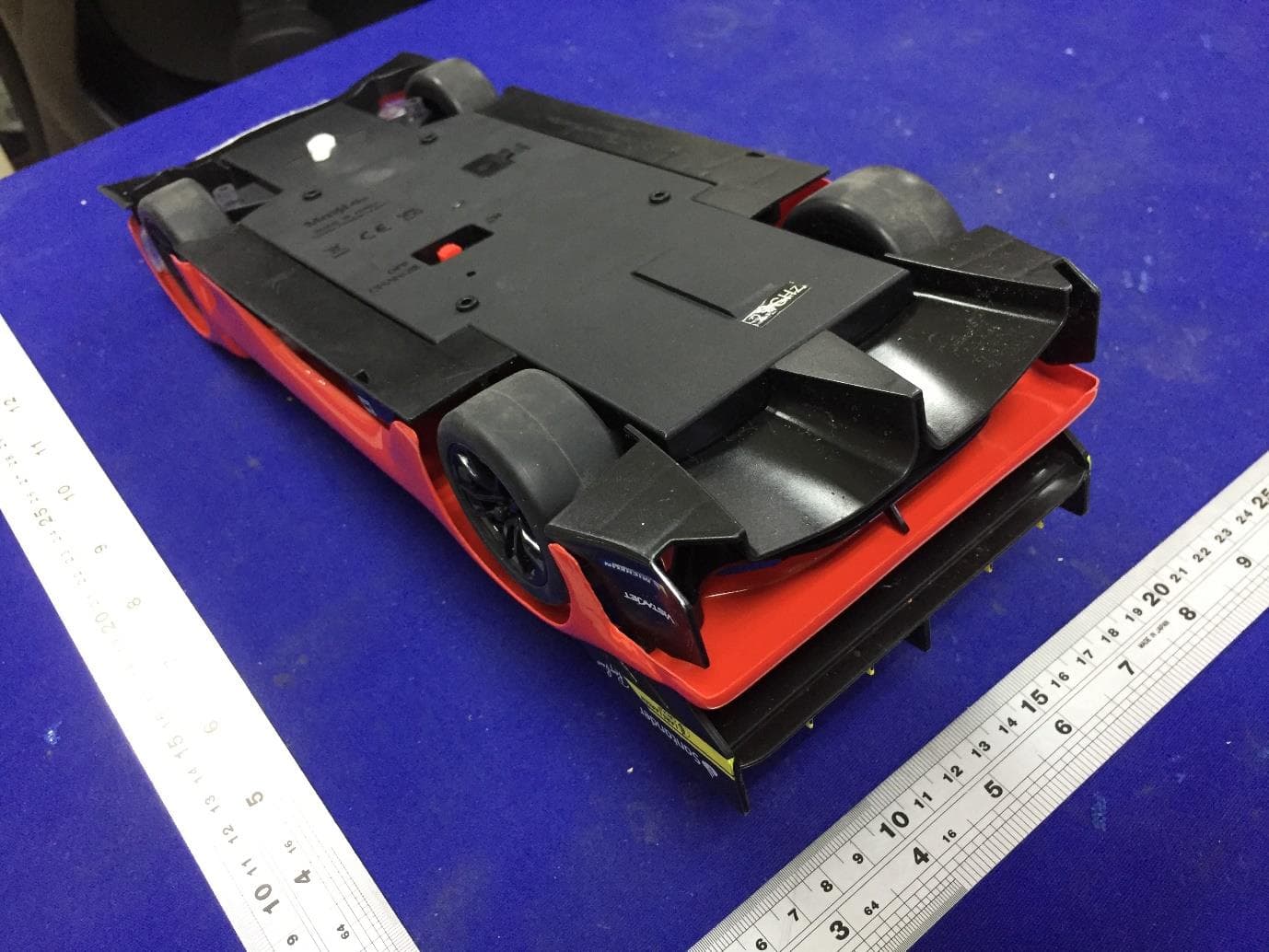
PKG82861RC
Jul 03, 20241 16 RC Ferrari 499P
Equipment Class
DXX - Part 15 Low Power Communication Device Transmitter
PKG23044RC
Nov 04, 2023Easy Drift Formula RC
Equipment Class
DXX - Part 15 Low Power Communication Device Transmitter
PKG81550RCA
Aug 07, 2023Radio Control Vehicle (2.4GHz Version)
Equipment Class
DXX - Part 15 Low Power Communication Device Transmitter