PKG81021RC49Remote Control Toy Transmitter
May Cheong Toy Products Fty. Ltd.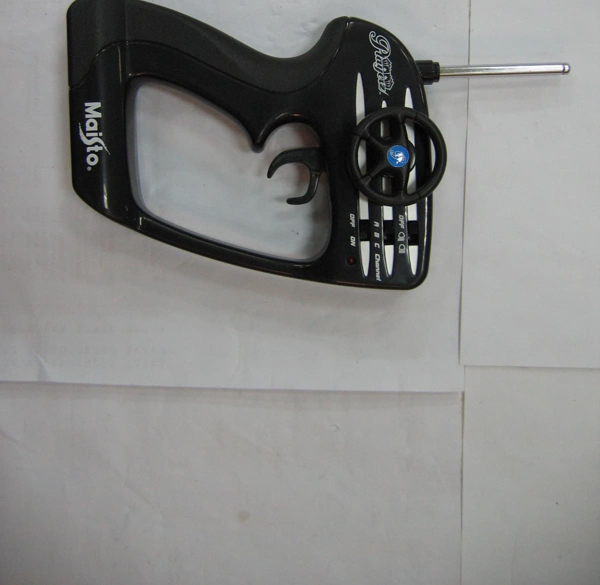
Click to zoom
Application Details
- Equipment Class
- DXX - Part 15 Low Power Communication Device Transmitter
- Date of Grant
- Apr 19, 2005
- Application Purpose
- Original Equipment
- Date of Application
- Apr 19, 2005
- Equipment Note
- Remote Control Toy Transmitter
- Frequency Range
- 49.86000000 - 49.86000000
- Country
- Hong Kong
Documents & Files
Document Text
Text extracted from the exhibit documents filed with the FCC. Open a document above to read the original.
Users Manual
The packaging has to be kept since it contains important information. Contents: RC Vehicle x 1 Transmitter x 1 Transmitter Antenna x 1 4-Hour Battery Charger x 1 9.6V Rechargeable Ni-Cd Battery Pack (For Vehicle Use) x 1 9V non-rechargeable Battery (For Transmitter Use) x 1 Instruction Manual x 1 Battery Charging: 1. Connect the 9.6V Battery Pack and the Charger connectors. 2. Plug the Charger into a standard 110V electrical outlet. 3. Charging time is around 4 hours. 4. Transmitter: Battery and Antenna Installation 1. Switch the power OFF. 2. Open the Battery Cover. 3. 4. Close the Battery Cover. 5. Screw the Antenna into the Transmitter securely. Vehicle: Battery Pack installation 1. Switch the power to the OFF position. 2. 3. 4. Close and lock the Battery cover. How to play: 1. Fully extend the Antenna of the Transmitter. 2. Match the Transmitter with the Vehicle Channel (Channel A or B or C). 3. Switch ON the Transmitter, the red LED will light up. 4. Switch ON the Vehicle. 5. The Headlight Features (OFF, Low beam and Hi-Beam) can be controlled on the Transmitter. 6. Pull the trigger to go forward, push it to go backward and release it to stop. 7. Turn the Transmitter steering wheel to move the Vehicle left or right. 8. If the Vehicle does not run in a straight line, adjust the wheel alignment arm on the Vehicle chassis. 9. Switch OFF the Transmitter and Vehicle power after playing. Turn the Battery Knob and lift up the Battery Cover. Install the Battery Pack into the battery compartment and plug it into the connector correctly. Install a 9V Battery with correct polarity (+/-) as shown inside the battery compartment. When charging is complete, detach the connectors and remove the Charger from the electrical outlet. Maisto Radio Control Vehicles Performance Tips: 1. Do not drive on grass, sand, carpet or go through water. 2. Do not drive in windy or rainy weather. 3. Avoid colliding with hard surfaces. 4. Switch OFF the Vehicle and Transmitter when not in use. 5. Remove all Batteries from the Vehicle and Transmitter when not in use. 6. Fully extend the antenna for best performance and do not point the antenna toward the vehicle. 7. Keep fingers, hair and loose clothing away from the wheels. 8. The operating range can be affected by a variety of factors: a) Weak Transmitter Battery, or under-charged Battery Pack. 9. Cautions : The 9.6V Battery Pack must be charged before use by utilizing the 4-Hour Battery Pack Charger which is included. Do not overcharge the Battery Pack. Do not charge for more than 6 hours. Do not charge the Battery Pack if it shows leakage, corrosion, or has loose or exposed wires or other damage. Do not cover the Battery Pack with any sort of material while charging. Do not dispose of the Battery in fire. Do not dismantle the Battery or Charger, and do not cut the Battery or Charger cables. The Battery Pack will be warm after charging, and hot after use in a vehicle. The supply terminals are not to be short-circuited. Rechargeable Batteries are to be removed from the toy before being charged. Rechargeable Batteries are only to be charged under adult supervision. FCC Label Compliance Statement: 81021RC49 FCC ID : PKG81021RC49 Tested To Comply with FCC Standards FOR HOME OR OFFICE USE This device complies with part 15 of the FCC rules. Operation is subject to the following two conditions : 1. This device may not cause harmful interference, and 2. This device must accept any interference received, including interference that may cause undesired operation. - Reorient or relocate the receiving antenna. - Increase the separation between the equipment and receiver. - Connect the equipment into an outlet on a circuit different from that to which the receiver is needed. - Consult the dealer or an experienced radio/TV technician for help. b) Interference from other items that emit radio frequency signals such as another R/C item on the same frequency, CB radios, cordless phones, high voltage transformers, etc. The Manufacturer is not responsible for any Radio or TV interference caused by unauthorized modifications to this equipment. Such modifications could void the User's Authority to operate the equipment. Do not touch the Battery Pack when it is hot. Wait until the Battery Pack cools before installing it in the vehicle and before recharging. Note that the 9V Battery is non-rechargeable and is not to be recharged. Only batteries of the same or equivalent type as recommended are to be used. It will need replacement when transmission is poor. Exhausted batteries are to be removed from the Transmitter. Note : This equipment has been tested and found to comply with the limits for a Class B digital device, pursuant to Part 15 of the FCC Rules. These limits are designed to provide reasonable protection against harmful interference in a residential installation. This equipment generates, uses and can radiate radio frequency energy and, if not installed and used in accordance with the instructions, may cause harmful interference to radio communications. However, there is no guarantee that interference will not occur in a particular installation. If this equipment does cause harmful interference to radio or television reception, which can be determined by turning the equipment off and on, the user is encouraged to try to correct the interference by one or more of the following measures: Outdoor usage is recommended in order to get optimal control range (100 feet or 30 meters). Regular examination of Battery Charger for any damage to their cord, plug, enclosure and other parts, and that, in the event of such damage, it must not be used with the Charger or Battery Pack charge until such damage has been repaired. Charge Only Ni-Cd Type (700mAH Max.) rechargeable Battery Packs. Other types of Batteries may burst causing injury to persons and damage. This power unit is intended to be correctly orientated in a vertical or floor mount position. Warranty FAQ (Frequently Asked Questions) 1)…
Text truncated - open the document above for the full version.
Block Diagram
Receiver circuit Transmitter curcuit Circuit Description Front Back Left Right Lamp Channel Transmitter IC C22RC01 Oscillating Amplify circuit Tunning DC 9V Press the buttonon the transmitterfor o p eration. IC generate signalto the externalam p lif y circuit. Signal will beamplified underthe Oscillatin g Suitablefrequency istunned on the 9V battery issupply to thetransmittin g The amplified signalis transmitted by theantenna. 9V battery issupply to thetransmittin g Front Back Left Right Lamp Channel Receiver IC C22RC01 Oscillating Amplify circuit Tunning DC 9.6V outputperformance. IC generate signalto the externalfunctional circuit. Signal will beamplified beforein p ut to the IC Suitablefrequency istunned on the 9.6V battery issupply to thereceivin g circuit. Antenna receive theamplified signal.
ID Label/Location Info
FCC ID Location FCC ID Label Sample FCC ID: PKG81021RC49 This device complies with Part 15 of the FCC Rules. Operation is subject to the following two conditions: (1) this device may not cause harmful interference, and (2) this device must accept any interference received, including interference that may cause undesired operation.
Operational Description
Circuit Description Transmitter circuit 1) B1 is the 9V 6F22 battery which is supplied to the transmitter. 2) Clock of the IC U1, 4MHz, is control by the crystal X2, C15 &C16. 3) Signal input to the IC which is corresponding to the button is pressed. 4) Input ports are included port 1, 2, 13, 14, 15, 16, 17, 18, 19 5) IC U1 will generated coded signal on the port 11. Then transmitted to the circuit when the button is pressed. 6) The generated signal will be adjusted and modulated with the 49.86MHz oscillator by the modulating circuit, X1, Q2, R7, C10 & L1. 7) Signal will then be amplified after pass through the amplifying circuit, Q1, C9, C3, C12, L2. 8) This amplified signal will be transmitted by the antenna. Receiver Circuit: 1) 9.6V rechargeable battery is supplied to the receiver circuit. 2) Antenna will received the modulated signal. 3) The modulated signal is tuned by the components Q1, L2, R2, C2, C3, C5, C29. port 17. 5) This amplified signal will decoded by the IC. 6) Output pulse will be generated by the IC on the output port. 7) Output port are included, port 1, 2, 13, 14, 19 & 20. 8) Corresponding function will be operated by the motor M2 & M1 and the LEDs, LED1-6. .
Test Report
Report No.: GLEMO050300568RFF Page: 1 of 12 FCC ID: PKG81021RC49 Authorized Signature: Kent Hsu Laboratory Manager This report refers to the General Conditions for Inspection and Testing Services, printed overleaf This report details the results of the testing carried out on one sample. The results contained in this test report do not relate to other samples of the same product and does not permit the use of the SGS PRODUCT CERTIFICATION MARK.. The manufacturer should ensure that all products in series production are in conformity with the product sample detailed in this report. This report may only be reproduced and distributed in full. If the product in this report is used in any configuration other than that detailed in the report, the manufacturer must ensure the new system complies with all relevant standards. Any mention of SGS International Electrical Approvals or testing done by SGS International Electrical Approvals in connection with, distribution or use of the product described in this report must be approved by SGS International Electrical Approvals in writing. The report must not be used by the client to claim product certification, approval, or endorsement by NVLAP, NIST, or any agency of the federal government. All test results in this report can be traceable to National or International Standards. Member of the SGS Group (SGS SA) SGS-CSTC Standards Technical Services Ltd. 1/F., Building No. 1 Building, Agriculture Machinery Materials Co. Wushan Road, Shipai, Tianhe District,Guangzhou, China Telephone: +86 (0) 20 3848 1001 Fax: +86 (0) 20 3848 1006 Email: [email protected] FEDERAL COMMUNICATIONS COMMISSION Registration number: 282399 FCC TEST REPORT Application No. : GLEMO050300568RF (SGS HK NO.: 2009345/EL) Applicant : May Cheong Toy Products Fty. Ltd. FCC ID : PKG81021RC49 Fundamental Frequency : 49.860MHz Equipment under Test (EUT): Name : 1:10 RC Remote Control Lamborghini Gallardo (Playerz)-Metallic Orange Model : 81021 Standards : FCC PART 15, SUBPART C : 2004 Section 15.235 Date of Receipt : 09 March 2005 Date of Test : 16 to 28 March 2005 Date of Issue : 30 March 2005 Test Result : PASS * * In the configuration tested, the EUT complied with the standards specified above. FCC ID: PKG81021RC49 Report No.: GLEMO050300568RFF Page: 2 of 12 SGS-CSTC Standards Technical Services Ltd. 2 Test Summary Test Test Requirement Stanadard Paragraph Result Radiated Emission (30MHz to 1000MHz) FCC PART 15 :2004 Section 15.235 PASS * Occupied Bandwidth FCC PART 15 :2004 Section 15.235 PASS Remarks: The EUT passed the Radiated Emission test after modification as shown as below: 1. Added one resistor (20kΩ) in series to R 9 2. Added one capacitor (0.01μF)to power line 3. Added one resistor (100kΩ) to R 7 4. Added one capacitor (10pF) to Q1 “B” “C” Pin 5. Added one capacitor (10pF) to Q1 “C” “E” Pin FCC ID: PKG81021RC49 Report No.: GLEMO050300568RFF Page: 3 of 12 SGS-CSTC Standards Technical Services Ltd. 3 Contents Page 1 COVER PAGE ...........................................................................................................................................1 2 TEST SUMMARY....................................................................................................................................................2 3 CONTENTS..............................................................................................................................................................3 4 GENERAL INFORMATION...................................................................................................................................4 4.1 CLIENT INFORMATION....................................................................................................................................... 4 4.2 DETAILS OF E.U.T............................................................................................................................................ 4 4.3 DESCRIPTION OF SUPPORT UNITS................................................................................................................... 4 4.4 TEST LOCATION................................................................................................................................................ 4 4.5 OTHER INFORMATION REQUESTED BY THE CUSTOMER.................................................................................. 4 4.6 TEST FACILITY................................................................................................................................................... 5 5 TEST RESULTS......................................................................................................................................................6 5.1 TEST INSTRUMENTS.......................................................................................................................................... 6 5.2 E.U.T. OPERATION........................................................................................................................................... 6 5.3 TEST PROCEDURE & MEASUREMENT DATA..................................................................................................... 6 5.3.1 Radiated Emissions...................................................................................................................................6 5.3.2 Occupied Bandwidth.................................................................................................................................8 5.3.3 Photographs - Radiated Emission Test Setup in Chamber.................................................................9 6 PHOTOGRAPHS - EUT CONSTRUCTIONAL DETAILS..........................................................................10-12 FCC ID: PKG81021RC49 Report No.: GLEMO050300568RFF Page: 4 of 12 SGS-CSTC Standards Technical Services Ltd. 4 General Information 4.1 Client Information Applicant: May Cheong Toy Products Fty. Ltd. Address of Applicant: 12/F., Empire Centre, …
Text truncated - open the document above for the full version.
Contact Information
Applicant
Anson Wang(QA Manager)
Test Firm
SGS-CSTC Standards Technical Services Co., LtdJerry Chan
Technical Specifications
| # | Rule Parts | Frequency Range | Power Output |
|---|---|---|---|
| 1 | 15C | 49.86 MHz - 49.86 MHz | - |
Other Applications from May Cheong Toy Products Fty. Ltd.
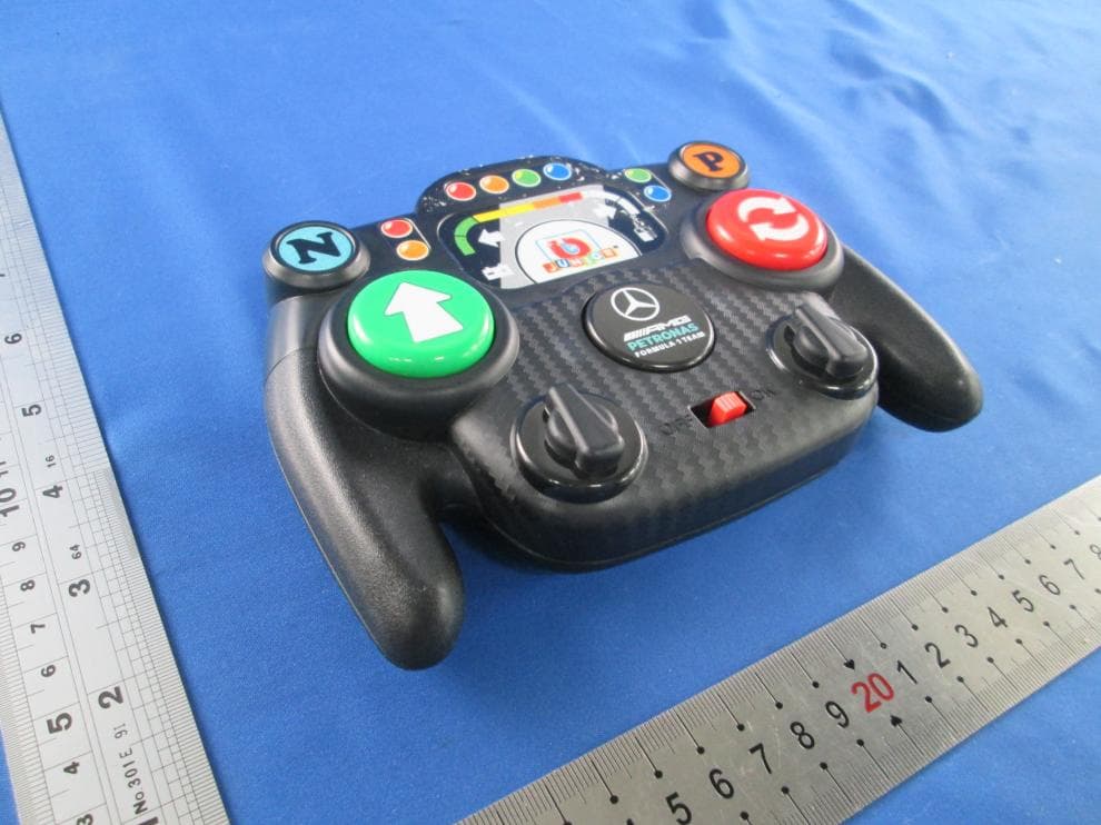
PKG25847RC
Jul 24, 2026MY FIRST FORMULA ASST(BB Junior - My First Formula RC - Mercedes-AMG)
Equipment Class
DXX - Part 15 Low Power Communication Device Transmitter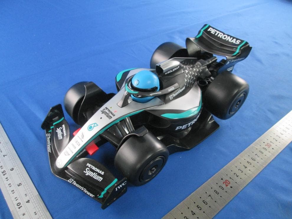
PKG91009RC
Jul 24, 2026MY FIRST FORMULA ASST(BB Junior - My First Formula RC - Mercedes-AMG)
Equipment Class
DXX - Part 15 Low Power Communication Device Transmitter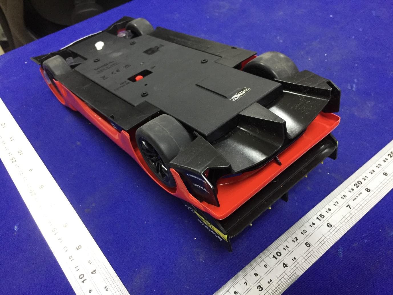
PKG82861RC
Jul 03, 20241 16 RC Ferrari 499P
Equipment Class
DXX - Part 15 Low Power Communication Device Transmitter
PKG23044RC
Nov 04, 2023Easy Drift Formula RC
Equipment Class
DXX - Part 15 Low Power Communication Device Transmitter
PKG81550RCA
Aug 07, 2023Radio Control Vehicle (2.4GHz Version)
Equipment Class
DXX - Part 15 Low Power Communication Device Transmitter