PKJDSR-301ADigital Satellite Receiver
AMT Co., Ltd.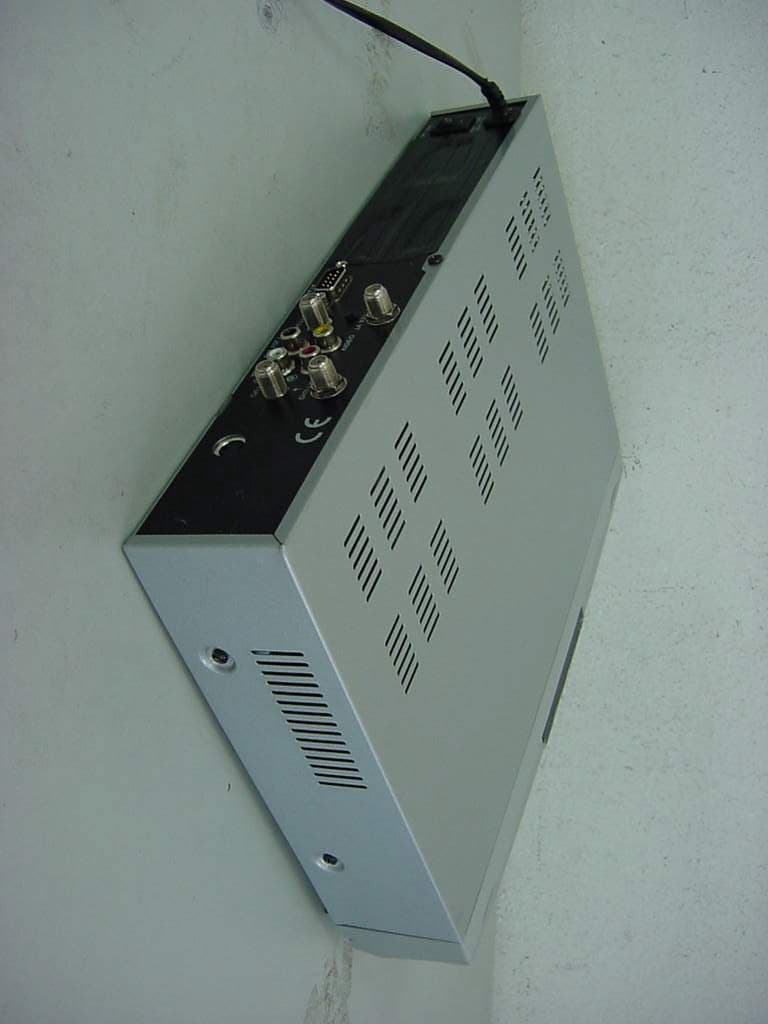
Click to zoom
Application Details
- Equipment Class
- HID - Part 15 TV Interface Device
- Date of Grant
- Jun 07, 2001
- Application Purpose
- Original Equipment
- Date of Application
- Jun 07, 2001
- Equipment Note
- Digital Satellite Receiver
- Frequency Range
- 67.25000000 - 71.75000000
- Company
- AMT Co., Ltd.
- Country
- South Korea
Documents & Files
Document Text
Text extracted from the exhibit documents filed with the FCC. Open a document above to read the original.
Users Manual
UserGuide DSR - 301 ACE INFORMATION TO THE USER II INFORMATION TO THE USER This equipment has been tested and found to comply with the limits for a Class B digital device, pursuant to part 15 of the FCC Rules. These limits are designed to provide reasonable protection against harmful interference in a residential installation. This equipment generates, uses and can radiate radio frequency energy and, if not installed and used in accordance with the instructions, may cause harmful interference to radio communications. However, there is no guarantee that interference will not occur in a particular installation. If this equipment does cause harmful interference to radio or television reception, which can be determined by turning the equipment off and on, the user is encouraged to try to correct the interference by one more of the following measures: Reorient or relocate the receiving antenna. Increase the separation between the equipment and receiver. Connect the equipment into an outlet on a circuit different from that to which the receiver is connected. Consult the dealer or an experienced radio/TV technician for help. Changes or modifications not expressly approved by the manufacturer could void the user's authority to operate the equipment. WARNING Information contained in this manual is subject to change without notice. No part of this publication may be copied, reproduced, or translated to another language for any purpose. FOR YOUR SAFETY Be sure to read the user manual before starting the operation of the receiver. Do not open the housing. The receiver contains high-voltage components and parts. Do not expose to rain or moisture. Do not make objects or fluid enter the housing through the ventilation slot. If any spilt liquid went into to the housing, unplug the power cord and call your local service provider. Do not place close to any heat source. Do not press with hard or heavy object. To protect possible malfunction by lighting, we recommend you to use power surge unit. Call your local dealer for advise. For Your Safety 1. Before Getting Started1 1.1 Main Features1 1.2 Accessories2 2. Controls and Functions3 2.1 Front Pannel3 2.2 Rear Pannel4 2.3 Remote Control Unit5 3. Connections7 3.1 Connecting to the TV, VCR and Satellite Antenna7 3.2 Connecting to the TV, HiFi system and 0/12V switch8 3.3 Connecting DiSEqC switch8 3.4 Connecting CA Module9 4. Settings and Operations10 4.1 Basic Settings10 4.2 Viewing TV(or Radio)13 4.3 Other functions17 4.4 System Settings18 4.5 CA Information21 5. Appendix22 5.1 Troubleshooting22 5.2 Specification22 5.3 Glossary23 III C O N T E N T S 1.1 Main Features Easy Menu Function TV Guide Function RF Output Function Electronic Program Guide(EPG) for On Screen Channel Information Software Upgrading Function Through RS-232C Cable by PC Perfect DiSEqC 1.2 and 0/12V Support for Various Antenna System or 2-LNB on 1 Antenna System Supports of Ku/C band, SCPC and MCPC Additional Audio Output Function for Connection to Hi-Fi Audio System Other Functions of Remote Controller, Receiving Level Selection, Channel Editing, Menu Language Selection and Audio Selection Digital free-to-air Satellite Receiver NTSC & PAL Output Function Regardless of the TV type, NTSC and PAL channels can be viewed by selection When PAL channel is viewed on NTSC TV, small deletion on up & down sides of the screen may occur and it is normal, as its conversion is managed by software. And darker color on the bottom side of the screen may occur, when NTSC channel is viewed on PAL TV. 500 Transponders and 2000 Channel Memory Function Teletext Supported Multi Language Function(Menu, Audio) Before Getting Started 1 1.2 Accessories User Manual Battery Remote Control Unit RCA cable 2 A c c e s s o r i e s 2.1 Front pannel STANDBY ON Turn the power on/off. MENU Shows the menu application. Channel Change channel, move menu, or input frequency value. Volume Control volume, change item on menu or input frequency value. OK Select menu or value on menu item. CI Slot Insert CI module into CI slot.(It is needed for only model contained Common Interface function) CONTROLS AND FUNCTIONS 3 2.2 Rear pannel DIGITAL It receives signals from the LNB in the range of 950 ~ 2150MHz. Connect a satellite dish to DIGITAL. OUT It sends signal to the another receiver. RS-232C It receives data by connecting to PC for software upgrading. Connect with RS-232C cable a PC and receiver. AUDIO It provides stereo audio output. Connect the audio on TV to AUDIO with RCA cable. VIDEO It provides composite video output. Connect the Video on TV to VIDEO with RCA cable. 0/12 VOLT It provides 0 or 12V output for external LNB switch. TV ANT IN The signal supplied to this connector from a TV antenna will be sent to TV antenna output. Connect a TV antenna to TV ANT IN. TV output It provides a modulated audio and video from the receiver. Connect the TV/VCR on TV to TV/VCR with the RF cable. ON/OFF The switch is to turn on or off the main power of the receiver mechanically. 4 Rear pannel 2.3 Remote Control Unit CONTROLS AND FUNCTIONS 5 POWER Turn the power on/off. TV/SAT Select between TV Channels and Satellite channels for RF output. Numeric(0~9) Mo ve me nu , cha nge c ha nne l or i npu t frequency value. CLEAR Clear wrong number input or delete channel from TV (Radio) list or favorite channel list. MUTE Deactivate current sound. MENU Shows the menu application. EXIT Exit from the menu. Page UP/DOWN Move to previous/next page on TV(Radio), Fa vor it e C han ne ls or Ed i t TV( Ra dio ) Channels. Volume Control volume, change item on menu or input frequency value. Channel Change channel, move menu, or input frequency value. OK Select menu or value on menu item. Open the controller cover on the back and insert two batteries (AA - 1.5V). PROGRAM GUIDE Shows the broadcasting information.(Video - Audio - LNB) INFORMATION Shows the information of current channel. Click the INFO button twice, TELETEXT mode will be displayed. FAVORITE Add TV or…
Text truncated - open the document above for the full version.
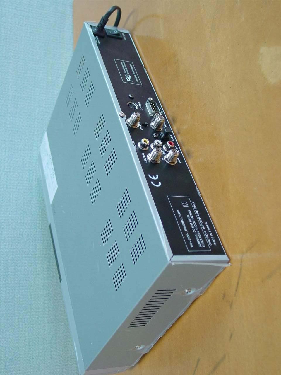
External Photos
FCC ID.: PKJDSR-301A File No.: E015R-051 ONETECH Testing & Evaluation Lab. FCC ID.: PKJDSR-301A File No.: E015R-051 ONETECH Testing & Evaluation Lab.
ID Label/Location Info
FCC ID. : PKJDSR-301A ONETECH Testing & Evaluation Lab. IDENTIFICATION LABEL: PROPOSED FCC ID LABEL The label included following statement will be attached on the rear side of product. This device complies with Part 15 of the FCC Rules. Operation is subject to the following two conditions: (1) this device may not cause harmful interference, and (2) this device must accept any interference received, including interference that may cause undesired operations. Made in Korea FCC ID : PKJDSR-301A FCC ID AREA
ID Label/Location Info
FCC ID. : PKJDSR-301A ONETECH Testing & Evaluation Lab. IDENTIFICATION LABEL: PROPOSED FCC ID LABEL The label included following statement will be attached on the rear side of product. This device complies with Part 15 of the FCC Rules. Operation is subject to the following two conditions: (1) this device may not cause harmful interference, and (2) this device must accept any interference received, including interference that may cause undesired operations. Made in Korea FCC ID : PKJDSR-301A FCC ID AREA
Internal Photos
FCC ID.: PKJDSR-301A File No.: E015R-051 ONETECH Testing & Evaluation Lab. FCC ID.: PKJDSR-301A File No.: E015R-051 ONETECH Testing & Evaluation Lab. FCC ID.: PKJDSR-301A File No.: E015R-051 ONETECH Testing & Evaluation Lab.
Internal Photos
FCC ID.: PKJDSR-301A File No.: E015R-051 ONETECH Testing & Evaluation Lab. FCC ID.: PKJDSR-301A File No.: E015R-051 ONETECH Testing & Evaluation Lab. FCC ID.: PKJDSR-301A File No.: E015R-051 ONETECH Testing & Evaluation Lab.
Internal Photos
FCC ID.: PKJDSR-301A File No.: E015R-051 ONETECH Testing & Evaluation Lab. FCC ID.: PKJDSR-301A File No.: E015R-051 ONETECH Testing & Evaluation Lab. FCC ID.: PKJDSR-301A File No.: E015R-051 ONETECH Testing & Evaluation Lab. FCC ID.: PKJDSR-301A File No.: E015R-051 ONETECH Testing & Evaluation Lab.
Internal Photos
FCC ID.: PKJDSR-301A File No.: E015R-051 ONETECH Testing & Evaluation Lab. FCC ID.: PKJDSR-301A File No.: E015R-051 ONETECH Testing & Evaluation Lab. FCC ID.: PKJDSR-301A File No.: E015R-051 ONETECH Testing & Evaluation Lab.
Test Report
Page 1 of 18 FCC ID. : PKJDSR-301A File No. : E015R-051 This report shall not be reproduced except in full without our written approval. EMC-004 (Rev.0) HEAD OFFICE : #505 SK APT. Factory 223-28, Sangdaewon 1 Dong, Jungwon-Gu, Seongnam-City, Kyunggi-Do, 462-121, Korea (TEL: 82-31-746-8500 FAX: 82-31-746-8700) EMC Dept. : 426-1 Daessangryung-Ri, Chowol-Myun, Kwangju-Si, Kyunggi-Do 464-860 Korea.(TEL:82-31-765-8289 FAX:82-31-766- 2904) ONETECH Testing & Evaluation Lab. ELECTROMAGNETIC EMISSION COMPLIANCE REPORT FOR FCC CLASS B CERTIFICATION Test report file number : E015R-051 Applicant : AMT CO., LTD. Address : 5F1. DaeA Venture Bldg., 1594-4, Seocho-Dong, Seocho-Gu, Seoul, 137-070, Korea Manufacturer : U-TECH CO., LTD. Address : 379-12 Chongchon-Dong, Pupyong-Gu, Inchon, 403-030, Korea Type of Equipment : Digital Satellite Receiver FCC ID. : PKJDSR-301A Model / Type No. : DSR-301A Serial number : N/A Total page of Report : 18 pages (including this page) Date of Incoming : May 03, 2001 Date of issue : May 29, 2001 SUMMARY The equipment complies with the regulation; FCC CFR 47 PART 15 SUBPART B, TV Interface Device. This test report contains only the result of a single test of the sample supplied for the examination. It is not a generally valid assessment of the features of the respective products of the mass-production. Reviewed by: Approved by: Y. K. Kwon / Chief Engineer S. S. Hong / Managing Director EMC Dept. ONETECH Corp. ONETECH Corp. Page 2 of 18 FCC ID. : PKJDSR-301A File No. : E015R-051 This report shall not be reproduced except in full without our written approval. EMC-004 (Rev.0) HEAD OFFICE : #505 SK APT. Factory 223-28, Sangdaewon 1 Dong, Jungwon-Gu, Seongnam-City, Kyunggi-Do, 462-121, Korea (TEL: 82-31-746-8500 FAX: 82-31-746-8700) EMC Dept. : 426-1 Daessangryung-Ri, Chowol-Myun, Kwangju-Si, Kyunggi-Do 464-860 Korea.(TEL:82-31-765-8289 FAX:82-31-766- 2904) ONETECH Testing & Evaluation Lab. CONTENTS PAGE 1. VERIFICATION OF COMPLIANCE...............................................................................................3 2. GENERAL INFORMATION............................................................................................................4 2.1 PRODUCT DESCRIPTION............................................................................................................................................................4 2.2 RELATED SUBMITTAL(S) / GRANT(S).................................................................................................................................4 2.3 TEST SYSTEM DETAILS.............................................................................................................................................................5 2.4 TEST METHODOLOGY.................................................................................................................................................................5 2.5 TEST FACILITY..............................................................................................................................................................................5 3. SYSTEM TEST CONFIGURATION................................................................................................5 3.1 JUSTIFICATION.............................................................................................................................................................................5 3.2 EUT EXERCISE SOFTWARE......................................................................................................................................................6 3.3 CABLE DESCRIPTION..................................................................................................................................................................6 3.4 NOISE SUPPRESSION PARTS ON CABLE..............................................................................................................................6 3.5 EQUIPMENT MODIFICATIONS.................................................................................................................................................6 3.6 CONFIGURATION OF TEST SYSTEM......................................................................................................................................7 3.6.1 Line Conducted Test................................................................................................................................................................7 3.6.2 Radiated Emission Test...........................................................................................................................................................7 3.6.3 Output Signal Level Test........................................................................................................................................................7 3.6.4 Output Terminal Conducted Spurious Emission test........................................................................................................7 3.6.5 Transfer Switch Isolation Test...............................................................................................................................................8 4. PRELIMINARY TEST.......................................................................................................................8 4.1 AC POWER LINE CONDUCTED EMISSION TEST...............................................................................................................8 4.2 RADIATED EMISSIONS TESTS.................................................................................................................................................8 5. FINAL RESULT OF MEASURMENT.............................................................................................9 5.1 CONDUCTED EMISSION TEST..................................................................................................................................................9 5.2 RADIATED EMISSION TEST...........…
Text truncated - open the document above for the full version.
Test Setup Photos
FCC ID. : PKJDSR-301A File No. : E015R-051 ONETECH Testing & Evaluation Lab. FCC ID. : PKJDSR-301A File No. : E015R-051 ONETECH Testing & Evaluation Lab.
Contact Information
Applicant
Lae Shin Park(Engineer)
Test Firm
ONETECH Corp.Y. Kwon
Technical Specifications
| # | Rule Parts | Frequency Range | Power Output |
|---|---|---|---|
| 2 | 15B | 67.25 MHz - 71.75 MHz | - |
Other Applications from AMT Co., Ltd.
PKJDSR-101PLUS
Feb 25, 2003Digital Satellite Receiver
Equipment Class
HID - Part 15 TV Interface Device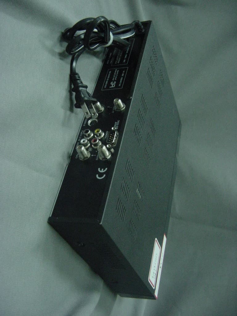
PKJDSR-101PA
Apr 19, 2001Digital Satellite Receiver
Equipment Class
HID - Part 15 TV Interface Device