PKKES433V1433.92 MHz Electronic Container Seal
eLogicity International Pte Ltd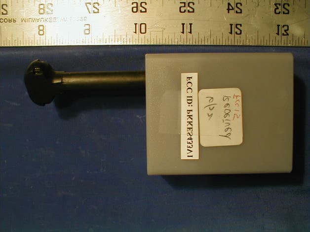
Click to zoom
Application Details
- Equipment Class
- DXX - Part 15 Low Power Communication Device Transmitter
- Date of Grant
- Aug 15, 2001
- Application Purpose
- Original Equipment
- Date of Application
- Aug 15, 2001
- Equipment Note
- 433.92 MHz Electronic Container Seal
- Frequency Range
- 433.92000000 - 433.92000000
- Country
- Singapore
Documents & Files
Document Text
Text extracted from the exhibit documents filed with the FCC. Open a document above to read the original.
Users Manual
Electronic Container SealConfidential P:\RFID\DOC\ECSSPEC2.DOCPage 1 7/31/2001 CONTROLLED DOCUMENT COVER PAGE DOC NO: 00-002-00000094 EFFECTIVE DATE: 24 January 2000 REV: A NO. OF PAGES: 12 (including this page) TITLE:ECS SPECIFICATIONS FOR EJ BROOKS SEAL COPY NO: 1.Office Copy 2. Softcopy Filename:P:\ECS\DOC_CON\EJ315\ECSSPEC.DOC PREPARED BY: Huang Li Gang Design Engineer Name Designation Signature APPROVED BY: Zhao Long Hardware Design Manager Name Designation Signature Revision Record REVDATECHANGED BY REASON FOR CHANGE A24/01/00Huang LGInitial Format Release Electronic Container SealConfidential P:\RFID\DOC\ECSSPEC2.DOCPage 2 7/31/2001 Electronics Container Seal Specifications 1.0 INTRODUCTION 1.0.1 Electronic Container Seal (ECS) is designed to be used by all shippers, aimed to improve the efficiency of port operation. 1.0.2 ECS shall be incorporation into present seal. 1.1 Power Up Sequence 1.1.1 Once the shipping operator completes the stuffing of goods into the container, the operator will lock the container with an ECS. 1.1.2 Shipping administrator will provide all information to Port Authority for clearance purpose; this shall include the ECS’s seal number, Container Number, Shipping Line and etc. 1.1.3 When the container reaches the Gate entrance, a Base Reader will read the ECS’s data electronically. 1.1.4 The read number will then be sent to the Authority’s system for verification. 1.1.5 Upon successful verification, the container will be allowed to proceed to its next level of work. If it fails, the necessary personnel will be notified. 1.2 Power Up Sequence 1.2.1 The scope of this report shall be restricted to only the specifications of the Electronic Container Seal (ECS) of RFID project. 1.2.2 By no means it serves to provide reader with an understanding of the entire RFID project. 1.2.3 It serves to provide reader with an understanding of the specifications of the ECS. 1.2.4 It starts by providing reader an overview of the system, outlining the necessary modules. 1.2.5 Transmission specifications were highlighted next to provide reader with some knowledge on the requirement of the transmitter. 1.2.6 The controller specifications, which include the Power-up Sequence, the Security Verification, Data Transmission, EEPROM Interface and Transmission Format, were presented for reader to understand the operation of the controller. 1.2.7 It ends with a brief outline of the electrical characteristics of the ECS. 2.0 SYSTEM OVERVIEW Electronic Container SealConfidential P:\RFID\DOC\ECSSPEC2.DOCPage 3 7/31/2001 Figure 1. Simplified ECS Block Diagram 2.0.1 The ECS consists of the blocks as shown above. 2.0.2 The controller provides the interface to the Memory. With the ECS’s information stored in the memory, the controller will encode the number into FSK data before sending them to the transmitter to be modulated. 2.0.3 The memory provides storage space for the ECS’s information. 2.0.4 The Transmitter is responsible for modulating the FSK data into FM signal. 2.0.5 The power supply shall come from a 3-Volt battery. 2.1 Power Up Sequence 2.1.1 The system shall be powered by external 3-volt battery. 2.1.2 The capacity of the battery shall be at least 1AH. 2.1.3 The shelf life with the battery shall be 1 year and the operating life will be 3 months. 2.2 Controller 2.2.1 It is the brain of the system. 2.2.2 Performing the necessary security verifications and ensure that the ECS is not tampered. 2.2.3 Providing the interface to Memory, capable of reading and writing data into the memory. 2.2.4 Encode data from memory into FSK format before sending them to the transmitter. 2.3 Memory 2.3.1 It is a non-volatile memory large enough to sore the ECS data. POWER SUPPLY CONTROLLER FM TRANSMITTER MEMORY Electronic Container SealConfidential P:\RFID\DOC\ECSSPEC2.DOCPage 4 7/31/2001 2.3.2 It shall allow random read and write to its address. 2.4 FM Transmitter 2.4.1 This module is responsible to transmit the seal number to the Base Reader. 2.4.2 Its responsible is to module the FSK data into FM signal before sending it over the air. 3.0 RF TRANSMISSION SPECIFICATIONS 3.0.1 The ECS sends its seal number to the Base Reader via Radio Frequency (RF). 3.0.2 The ECS has a 433.92MHz RF transmitter, which transmits 433.92MHz FM signal. 3.0.3 It receives data from the Controller. The data from the Controller is FSK encoded and the amplitude shall be 0 to VCC. 3.0.4 The FSK data shall then be frequency modulated into 433.92MHz FM signal. 3.0.5 The Oscillator shall use a SAW Resonator type circuit. 3.0.6 The transmitter output impedance shall be 50Ω. 3.0.7 When no transmission is required, the power to it shall be switched off. 3.0.8 All Specifications must meet the FCC Standard Part 15 and Europe Standard ETSI T-ETS 300 200. Electronic Container SealConfidential P:\RFID\DOC\ECSSPEC2.DOCPage 5 7/31/2001 3.1 Transmitter Technical Specifications 3.1.1 The followings are the specifications for the transmitter S/NPARAMETERSPECIFICATIONSREMARK 1Carrier Frequency433.92MHz+200KHz 2Output Power -10dBm @ 50Ω 3Spurious Harmonics>= -28dBc 4Frequency Deviation>32KHz+1KHz 5Max. Data Baud Rate16.384Kbps 6Output ImpedanceBetter than 13dBm into a 50Ω load 7Temperature Stability+50ppm at operating temperature 8Modulation ModeFrequency Modulation Table1: RF Transmitter Specification 4.0CONTROLLER SPECIFICATIONS 4.0.1The controller is the "Brain" of the Electronic Container Seal (ECS), responsible to verify the condition of the seal, read the data from the memory, encode the read data into its Frequency-shift-keying format and send the FSK data to the Transmitter for modulation before being transmitted. 4.1Power Up Sequence 4.1.1 An ECS can only be powered once. Subsequent power up will be regarded as tampered and tamper code will be sent in addition to the stored data. 4.1.2 The power up sequence of the controller shall be as follow: Electronic Container SealConfidential P:\RFID\DOC\ECSSPEC2.DOCPage 6 7/31/2001 Power Up Verifi…
Text truncated - open the document above for the full version.
Block Diagram
Transmitter 433.92MHz Antenna Encode Rate: 16kbps Controller EEPROM MCU Power Supply E-seal 433.92MHz
External Photos
EUT - Front View EUT- Bottom View
ID Label/Location Info
FCC ID Label Specifications: Text is black in color and is left justified. Labels are printed in indelible ink on permanent adhesive backing and shall be affixed at a conspicuous location on the EUT. Proposed Label Location on EUT FCC ID: PKKES433V1 This device complies with Part 15 of the FCC Rules. Operation is subject to the following two conditions: (1) this device may not cause harm- ful interference, and (2) this device must accept any interference received, including interference that may cause undesired operation. 0.5" 1.0" Bottom Side of EUT FCC Label Location FCC ID: PKKES433V1 This device complies with Part 15 of the FCC Rules. Operation is subject to the following two conditions: (1) this device may not cause harm- ful interference, and (2) this device must accept any interference received, including interference that may cause undesired operation.
Internal Photos
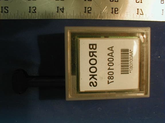
EUT-Circuit Component View EUT-Circuit Solder View
Operational Description
The brief description for the Eseal (433.92 MHz) 1. The Eseal (433.92MHz) consists of the block as shown above 2. The controller provides the interface to the Memory. With the ECS’s information stored in the memory, the controller will encode the number into FSK data before sending them to the transmitter to be modulated. 3. The memory provides storage space for the ECS’s information. 4. The transmitter is responsible for modulating the FSK data into FM signal. 5. The power supply shall come form a 3-Volt battery. The followings are the specifications fro the transmitter S/NParameterSpecificationRemark 1Carrier Frequency433.92 MHz 2Output Power-10dBm@50Ù 3Spurious Harmonics>=-28dBc 4Frequency Deviation>32kHz±1kHz 40kHz±1kHz in phase 2 5Max. Data Baud Rate16.384kbps 6Output Impedance Better than 13dBm into a 50 Ù load 7Temperature Stability ±50ppm at operating temperature 8Modulation Mode Frequency Modulation Power Supply FM Transmitter Controller Memory
Parts List/Tune Up Info
CONFIDENTIAL S/NManufacturer Part No.eLogicity P/NDesignatorFootprintQty 1ESTEC C/O KAINOSPCB-P008-001-0046-------------------1 2OPEN SOURCERES030303-0344R7SMT 06031 3OPEN SOURCERES030303-0345R3SMT 06031 4OPEN SOURCERES030303-0339R1SMT 06031 5OPEN SOURCERES030303-0340R2, R5SMT 06032 6OPEN SOURCERES030303-0346R6SMT 06031 7OPEN SOURCERES030303-0341R4SMT 06031 8OPEN SOURCERES030303-0347R8SMT 06031 9OPEN SOURCECAP07030701-0100C8, C10SMT 06032 10OPEN SOURCECAP07030701-0148C4, C9SMT 06032 11OPEN SOURCECAP07030703-0143C5, C6SMT 06032 12OPEN SOURCECAP07030703-0142C1, C2SMT 06032 13OPEN SOURCECAP07030704-0144C11SMT 06031 14OPEN SOURCECAP07030704-0113C12SMT 06031 15OPEN SOURCECAP07040504-0112C3, C7SMT 08052 CHIP CAP CERAMIC 5 pF + 5% (NPO) CHIP CAP CERAMIC 30pF +5% (NPO) eLogicity International 2nd Level - Bill of Materials for EJ Seal\NEC\433.92MHz\32kHz CHIP RES 47K OHMS 1/10W + 5% CHIP RES 100K OHMS 1/10W +5% CHIP CAP CERAMIC 1 pF + 0.25pF (NPO) CHIP CAP CERAMIC 2.2 pF + 0.25pF (NPO) CHIP CAP CERAMIC 100 pF + 10% (NPO) CHIP CAP CERAMIC 10 nF + 10% (X7R) CHIP CAP CERAMIC 100 nF + 10% (X7R) Description BARE PRINTED CIRCUIT BOARD, DOUBLE SIDED, FR4 #0046 CHIP RES 15 OHMS 1/10W + 5% CHIP RES 200 OHMS 1/10W + 5% CHIP RES 1K OHMS 1/10W + 5% CHIP RES 10K OHMS 1/10W + 5% CHIP RES 22K OHMS 1/10W + 5% REV: APage 2 of 3Date: 19/03/01 CONFIDENTIAL S/NManufacturer Part No.eLogicity P/NDesignatorFootprintQty eLogicity International 2nd Level - Bill of Materials for EJ Seal\NEC\433.92MHz\32kHz Description 16OPEN SOURCEIND070002-0040L1SMT 08051 17R670 EPCOSSAW020100-0007Y2TO39-31 AS-5.000-20-EXT RALTRON BEIJING YUNIKE S2- 5.0 FAST LOGIC L405000XFSD16XX HI-TECH HT93LC46-A (HOLTEK) 93LC46BT-1/SN (MICROCHIP) S-93LC46ADFJ-TB (SEKIO) 20 NEC MCU UPD78P9011GT IC000017-0138U1SOP281 21 MMBT3906LT1 SOT23 (MOTOROLA) PNP TRAN040400-0012Q1SOT 231 22 NPN MMBT3904LT1 SOT23 (MOTOROLA) TRAN050400-0007Q2SOT 231 BFR92A PHILIPS SOT23 NPN PNP MMBR901LT1 SOT23 (MOTOROLA) 24EJBOL-002-0084J1, J2, J3--------3 18 19 NEC MCU UPD78P9011GT TRANSISTOR PNP MMBT3906LT1 SOT23 (MOTOROLA) SAW RESONATOR 433.92 MHz CRYSTAL HC-49/S 5MHz IC MEMORY EEPROM HT93LC46 CHIP IND 22 nH + 5% CYS010100-0016 IC200004-0088 TRAN050400-0014 U2 Q3 1 Y1TH1 1 TRANSISTOR NPN MMBT3904LT1 SOT23 (MOTOROLA) SO8 TRANSISTOR NPN SOT23 ECS RETAINER RING 23SOT 23 REV: APage 3 of 3Date: 19/03/01
Schematics
123456 A B C D 654321 D C B A Revisions Revision: Number: Title Checked By: Approved By: File:Sheet: Drawn By: Date: P-SERV TECHNOLOGIES PTE LTD Blk 1093 Lower Delta Road #07-05\08 Tiong Bahru Industrial Estate Singapore 169204 A 00-017-00000134 23-Apr-2001 TAG 433.92 MHZ 11ofD:\ECS\TAG\433\NEC\0046\ECS_SIEA.SCH CONFIDENTIAL Tamper Detector 1 Program 2 IC 3 RESET 4 X2 5 X1 6 VSS 7 VDD 8 CS 12 SK 11 DO 10 DI 9 MODE 13 RF TEST 14 P06 15 P07 16 P10 17 P11 18 P12 19 P13 20 P14 21 P15 22 P16 23 P17 24 PWDN 25 P21 26 P22 27 FSK DATA 28 U1 UPD78P9011GT 1 J3 TAMPER PROGRAM Y1 5.0MHz C1 30pF C2 30pF VCC R1 1K C3 0.1uF VCC C7 0.1uF VCC VCC CS SK DO DI R2 10K TP1 TP CS SK DO DI PROGRAM VCC GND 1 2 3 4 5 6 7 J2 CON7 R4 47K VCC AVCC 2 1 3 Q2 MMBT3904 1 23 Y2 433.92MHz C8 1pF 2 1 3 Q3 RF TRANSISTOR R5 10K R6 22K R7 15R R3 200R C4 2.2pF C5 5pF C6 5pF C9 2.2pF L1 22nH C10 1pF J1 ANTENNA C11 100pF C12 10nF AVCC JP1 JP JP2 JP TWWONG Q1 MMBT3906 DO 4 DI 3 SK 2 CS 1 NC 7 NC 6 GND 5 VCC 8 U2 HT93LC46A GND 433.92 Mhz / 32k VCC 3V 1 J5 V+ Battery 1 J4 GND RING CONTACT 1 2 J6 CON2 R8 100K PROTOTYPE A (0046)A 26032001
Test Report
Note: This report may not be duplicated without prior written consent of Bay Area Compliance Laboratory Corporation. This report must not be used by the client to claim product endorsement by NVLAP or any agency of the U.S. Government. FCC ID PER PART 15.231 EMI MEASUREMENT AND TEST REPORT For eLogicity International Pte Ltd 78 Shenton Way, #22-01 Singapore 079120 FCC ID: PKKES433V1 July 18, 2001 This Report Concerns: Original Report Equipment Type: Electronic Container Seal Transmitter (433.92 MHz) Test Engineer:Jeff Lee Test Date:June 8, 2001 Reviewed By: John Y. Chan – Engineering Manager Prepared By:Bay Area Compliance Laboratory Corporation 230 Commercial Street, Suite 2 Sunnyvale, CA 94085 Tel: (408) 732-9162 Fax: (408) 732-9164 eLogicity International Pte Ltd FCC ID: PKKES433V1 Report # R0106081Page 2 of 26FCC ID Per 15.231 Report TABLE OF CONTENTS 1 - GENERAL INFORMATION........................................................................................................................................3 1.1 PRODUCT DESCRIPTION FOR EQUIPMENT UNDER TEST (EUT)...................................................................................3 1.2 OBJECTIVE.....................................................................................................................................................................3 1.3 RELATED SUBMITTAL(S)/GRANT(S).............................................................................................................................3 1.4 TEST METHODOLOGY....................................................................................................................................................3 1.5 TEST FACILITY...............................................................................................................................................................3 1.6 TEST EQUIPMENT LIST..................................................................................................................................................4 1.7 EQUIPMENT UNDER TEST (EUT)..................................................................................................................................4 2 - SYSTEM TEST CONFIGURATION...........................................................................................................................5 2.1 JUSTIFICATION...............................................................................................................................................................5 2.2 BLOCK DIAGRAM..........................................................................................................................................................5 2.3 EQUIPMENT MODIFICATIONS........................................................................................................................................5 2.4 TEST SETUP BLOCK DIAGRAM......................................................................................................................................6 3 - CONDUCTED EMISSIONS TEST DATA.................................................................................................................7 4 - RADIATED EMISSION DATA....................................................................................................................................8 4.1 EUT SETUP....................................................................................................................................................................8 4.2 SPECTRUM ANALYZER SETUP.......................................................................................................................................8 4.3 TEST PROCEDURE..........................................................................................................................................................8 4.4 CORRECTED AMPLITUDE & MARGIN CALCULATION..................................................................................................8 4.5 SUMMARY OF TEST RESULTS........................................................................................................................................9 4.6 RADIATED EMISSIONS TEST RESULT DATA.................................................................................................................9 APPENDIX A:......................................................................................................................................................................10 APPENDIX B:......................................................................................................................................................................12 APPENDIX C:......................................................................................................................................................................14 eLogicity International Pte Ltd FCC ID: PKKES433V1 Report # R0106081Page 3 of 26FCC ID Per 15.231 Report 1 - GENERAL INFORMATION 1.1 Product Description for Equipment Under Test (EUT) The eLogicity International Pte Ltd, model ES433V1 or the "EUT" as referred to in this report is a 433.92 MHz RF transmitter which is a part of the Electronic Container Seal (ECS) designed to be used by all shippers, aimed to improve the efficiency of port operation. It shall be incorporation into present seal. The EUT measures approximately 4.5” L x 2.1” W x 1.2” H. 1.2 Objective This Type approval report is prepared on behalf of eLogicity International Pte Ltd in accordance with Part 2, Subpart J, and Part 15, Subparts A and B of the Federal Communication Commissions rules. The objective of the manufacturer is to demonstrate compliance with FCC rules, Part 15, sec 231 for conducted and radiated margin. 1.3 Related Submittal(s)/Grant(s) No Related Submittals 1.4 Test Methodology All measurements contained in this report were conducted with ANSI C63.4 –1992, American National Standard for Methods of Measurement of Radio-Noise Emissions from Low-Voltag…
Text truncated - open the document above for the full version.
Test Setup Photos
Radiated Emission Photograph – Front View Radiated Emission Photograph – Rear View
Contact Information
Applicant
Yam Seng Tan(Senior Hardware Design Engineer)
Technical Contact
Bay Area Compliance Laboratory Corp.John Chan
[email protected]408 732 9162
230 Commercial Street · Sunnyvale, California · United States
Non-Technical Contact
Bay Area Compliance Laboratory Corp.Dayang Ji
[email protected]408 732 9162
Test Firm
Bay Area Compliance LaboratoryJohn Chan
Technical Specifications
| # | Rule Parts | Frequency Range | Power Output |
|---|---|---|---|
| 1 | 15C | 433.92 MHz - 433.92 MHz | - |
Other Applications from eLogicity International Pte Ltd
PKKES315V2
May 03, 2001Electronic Container Seal Transmitter (315MHz)
Equipment Class
DXX - Part 15 Low Power Communication Device Transmitter