PKRNVWE351PC EXPRESS CARD
Inseego Corp.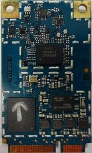
Click to zoom
Application Details
- Equipment Class
- PCB - PCS Licensed Transmitter
- Date of Grant
- Feb 08, 2012
- Application Purpose
- Original Equipment
- Date of Application
- Jan 11, 2012
- Equipment Note
- PC EXPRESS CARD
- Frequency Range
- 782.00000000 - 782.00000000
- Company
- Inseego Corp.
- Country
- United States
Documents & Files
Document Text
Text extracted from the exhibit documents filed with the FCC. Open a document above to read the original.
Users Manual
Novatel Wireless Inc. Version 2.1 Page 1 of 18 Novatel Wireless, Inc. PCI Express Mini-card Installation Guidelines for E351 Version 2.1 Novatel Wireless Inc. Version 2.1 Page 2 of 18 Notice: Restricted Proprietary Information © Copyright Novatel Wireless, Inc. (2012) The information contained in this document is the exclusive property of Novatel Wireless, Inc. All rights reserved. Unauthorized reproduction of this manual in any form without the expressed written approval of Novatel Wireless, Inc. is strictly prohibited. This manual may not, in whole or in part, be copied, reproduced, translated, or reduced to any electronic or magnetic storage medium without the written consent of a duly authorized officer of Novatel Wireless Inc. The information contained in this document is subject to change without notice and should not be construed as a commitment by Novatel Wireless Inc. unless such commitment is expressly given in a covering document. Novatel Wireless Inc. makes no warranties, either expressed or implied, regarding this document, its merchantability, or its fitness, for any particular purpose. Printed and produced in United States of America. Novatel Wireless Inc. Version 2.1 Page 3 of 18 Document Revision History Rev. Date Brief Description of Change Originator Approved by 1.0 August 6, 2011 Initial Draft Todd Gallagher 2.0 February 3, 2012 Responses to FCC Inquiries Tracking# 409406 Roman Olmos Todd Gallagher 2.1 February 22, 2012 Update made to 1900MHz Antenna Gain Information Roman Olmos Todd Gallagher Novatel Wireless Inc. Version 1.0 Page 4 of 18 FCC KDB Publication Reference KDB Title Version Date Attachment Number Version Number SAR Evaluation Considerations for Laptop/Notebook and Tablet computers KDB 616217 11/13/2009 D03 v01 Mobile and Portable Device RF Exposure Procedures and Equipment Authorization Policies KDB 447498 11/13/2009 D01 v04 SAR Considerations for LTE Handsets and Data modems KDB 941225 12/15/2010 D05 v01 Modular Transmitter Approvals KDB 996369 07/12/2011 D01 v01r03 Permissive Change Policy KDB 178919 06/08/2011 D01 v05r01 Software Configuration Control KDB 594280 06/08/2011 D01 v01r01 Novatel Wireless Inc. Version 1.0 Page 5 of 18 E351 Module Installation and Collocation Guidelines 1.0 Introduction This document provides collocation and installation instructions for future laptop computers through a FCC Class I or a Class II Permissive Change based on the PKRNVWE351 SAR data and evaluation. This process is documented in FCC KDB 616217 D03 and KDB 447498. Other configurations not specifically described in this document may be authorized in a Class I permissive changes through coordination with Novatel Wireless Inc. to verify that all technical requirements defined in FCC KDB 616217 D03 or other relevant FCC specifications are adequately addressed. For other basics and details about FCC RF exposure compliance requirements for mobile and portable devices, see FCC OET Bulletin 65 Supplement C. The following installation host configurations are addressed in this document. 1) The E351 module can be installed as a standalone transmitter in notebooks meeting the following conditions: a. Mobile device notebooks where >20cm separation distance is provided between the WWAN antenna and the end user can be processed as a Class I change. The technical parameters for mobile measurements are defined in Section 2.1.1. b. Portable device notebooks where ≤20cm separation distance is provided between the WWAN transmitting antenna that meet the technical parameters defined in Section 2.1.2. These parameters define the conservative notebook configuration used as the baseline host to evaluate SAR. Note: “Standalone” condition is defined where a single transmitter is transmitting, as opposed to two or more transmitters transmitting simultaneously. 2) This module was evaluated with a PIFA antenna (manufacturer xx, model xxx). As the antenna is an integral part of the integration each antenna type will be subject to will be subject to additional RF exposure evaluation and certification if applicable. The E351 will allow collocated transmission through a Class I or Class II permissive change. The collocated transmitters must meet the technical requirements defined in Section 4.0. and only after such Class I or Class II is complete and according to its conditions. 3) Allow end-user installation provided module/notebook Two-Way Authentication has been addressed so that modules can only be activated in approved notebooks 4) The FCC ID must be permanently affixed on the exterior of the notebook so that it cannot be separated from the host device itself. The label used must state; Contains FCC ID: PKRNVWE351 5) Per KDB 594280 Novatel Wireless Inc. will maintain control over settings that could allow the product to operate outside the FCC rules. 6) These installation guidelines are not applicable to non-notebook host devices or tablet PCs. The installation guidelines are applicable for notebook computers where the E351 antennas and collocated antennas are located in the display portion of a notebook computer. SAR evaluation is completed with the display open at a ninety-degree angle as defined in KDB pub 616217 and Section 4 of KDB pub 447498. Novatel Wireless Inc. Version 1.0 Page 6 of 18 2.0 Module Installation Guidelines This section defines host installation limitations for mobile device and portable device hosts. (See section 3.0 for mobile and portable definitions). 2.1.1 Mobile Device Hosts (WWAN to user separation distance >20cm) 2.1 Installation Guidelines The E351 module can be installed for use in any authenticated mobile device notebook as long as the antenna gain of the host antenna does not exceed the gain listed in table 1. (See section 3.0 for the measurement guidelines of separation between the transmitting antenna and the user.) The modem must not be collocated with other antennas or transmitters unless the guidelines are followed within this document. Please refer to…
Text truncated - open the document above for the full version.
Attestation Statements
Federal Communications Commission Equipment Authorization Division 7345 Oakland Mills Road Columbia, Maryland 21046 Subject: MPR Attestation FCC Certification No: PKRNVWE351 Novatel Wireless declares the following: 1) The LTE Maximum Power Reduction (MPR) is a mandatory feature that is built- in by the design. The feature is permanent and cannot be changed by the end user or the network operators. 2) The LTE MPR meets the applicable 3GPP TS 36.101 technical specification requirements (Table 6.2.3-1). MPR targets and maximum output power is permanently limited for the configurations specified in this table: Modulation Channel Bandwidth/Transmission Bandwidth Configuration (RB) MPR (dB) Target MPR (dB) BW 5MHz 10MHz QPSK >8 >12 1 ≤ 1 16QAM ≤8 ≤12 1 ≤ 1 16QAM >8 >12 2 ≤ 2 3) The device was tested for SAR with A-MPR disabled 4) The device cannot transmit as a higher power than identified in the Tune up procedures. Sincerely, Roman Olmos Sr. Regulatory Technologist Novatel Wireless Inc.
Cover Letter(s)
Request for Modular Approval – FCC ID: PKRNVWE351 Item Requirements EUT Compliance 1 The module has its own RF shielding Meets requirements. 2 The module must have buffered modulation/data input(s) to ensure that the module will comply with FCC Part 15 requirements with any type of input signal. Meets requirements. 3 The module has its own power supply regulation. Meets requirements. 4 The module must contain a permanently attached antenna, or contain a unique antenna connector, and be marketed and operated only with specific antenna(s) per Sections 15.203, 15.204(b), 15.212(a), 2.929(b). Meets requirements. 5 The module must demonstrate compliance in a stand-alone configuration Meets requirements. 6 The module must be labeled with its permanently affixed FCC ID label, or use an electronic display Meets requirements. 7 The module must comply with all specific rules applicable to the transmitter. The grantee must provide comprehensive instructions to explain compliance requirements Meets requirements. 8 The module must comply with RF exposure requirements. If SAR compliance can only be demonstrated in specific host types or platforms, then the module type must be “limited.” Meets requirements. Sincerely, Todd Gallagher Manager – Regulatory Engineering Novatel Wireless Inc.
Cover Letter(s)
September 1, 2011 Federal Communications Commission Authorization & Evaluation Division 7345 Oakland Mills Road Columbia, Maryland 21046 Re: Signing Authority on Form 731 per 852134 D01 Dear Sirs: I herby authorize Roman Olmos to sign all engineering attestations, cover letters and any other correspondence regarding the Grant submittal for the products bearing the FCC ID: PKRNVWE351. Sincerely, Todd Gallagher Manager – Regulatory Engineering Novatel Wireless Inc.
Cover Letter(s)
Proprietary and Confidential NOVATEL WIRELESS, INC. 9645 Scranton Road, Suite 205, San Diego, CA 92121 Toll Free: 888.888.9231 Main: 858.812.3400 Fax: 858.812.3402 Internet: www.novatelwireless.com ISO 9001: 2000 Date: September 9, 2011 Federal Communications Commission Equipment Authorization Division, Application Processing Branch 7435 Oakland Mills Road Columbia, MD 21048 Subject: Request for Confidentiality FCC ID: PKRNVWE351 To Whom It May Concern: In accordance with 47CFR0.459, Novatel Wireless Inc. requests long term confidentiality for the following items 1. E351 BOM (Bill of Material) 2. E351 Tuning Procedure 3. E351 Schematics Diagrams 4. E351 Theory of Operation 5. E351 Block Diagram In accordance with 47CFR0.457 and 0.459, Novatel Wireless Inc. requests short-term confidentiality for 180 days on the following items 1. E351 External and Internal Photos 2. E351 Integration Guide These items contain detailed system and equipment description and related information about the product which Novatel Wireless Inc. considers to be proprietary, confidential, and a custom design which otherwise would not be released to the general public. Since this design is a basis from which future technological products will evolve, Novatel Wireless Inc. also feels that this information would be of benefit to its competitors, and that the disclosure of the information in these exhibits would give our competitors an unfair advantage in the market. Sincerely, Todd Gallagher Manager – Regulatory Engineering Novatel Wireless Inc.
External Photos
Proprietary and Confidential NOVATEL WIRELESS, INC. 9645 Scranton Road, Suite 205, San Diego, CA 92121 Toll Free: 888.888.9231 Main: 858.812.3400 Fax: 858.812.3402 Internet: www.novatelwireless.com ISO 9001: 2000 Novatel Wireless Garter1 E351 Embedded Module Internal/External Illustration I.Top Side PCB External Internal II. Bottom Side PCB External Internal
ID Label/Location Info
LABEL ASSEMBLY, MEID, E351 GARTER 1, GENERIC Part Number: DA.01019XXX Rev A Chuck Morningstar Novatel Wireless, Inc. MEID Example: “XXXXXXXXXXXXXXX” DataMatrix 18 X 18 ECC type: 200 18 mil 11.5 mm 24 mm Blank Label Stock 25015894 White 24 mm X 11.5 mm Text: “MEID: ???????????????” MEID-DEC of modem Verdana 4pt Bold Model Type: “E351” Verdana 9pt Bold TEXT: “IC: 3229A-E351” “FCC ID:PKRNVWE351” Verdana 3 pt, Bold TEXT: “MADE IN KOREA” Verdana 3 pt, Bold AUG 17, 2011 Text: IMEI: ???????????????C” IMEI-DEC of modem Verdana 4pt Bold
ID Label/Location Info
Proprietary and Confidential NOVATEL WIRELESS, INC. 9645 Scranton Road, Suite 205, San Diego, CA 92121 Toll Free: 888.888.9231 Main: 858.812.3400 Fax: 858.812.3402 Internet: www.novatelwireless.com ISO 9001: 2000 Regulatory Label Location “FCC Label Placement”
Internal Photos
Proprietary and Confidential NOVATEL WIRELESS, INC. 9645 Scranton Road, Suite 205, San Diego, CA 92121 Toll Free: 888.888.9231 Main: 858.812.3400 Fax: 858.812.3402 Internet: www.novatelwireless.com ISO 9001: 2000 Novatel Wireless Garter1 E351 Embedded Module Internal/External Illustration I.Top Side PCB External Internal II. Bottom Side PCB External Internal
RF Exposure Info
Novatel Wireless Appendix Responses July 28, 2011 Identifying the wireless operating configurations and parameters for submitting a laboratory testing KDB inquiry, a TCB PBA or preparing SAR reports: 1) identify the operating frequency range of each LTE transmission band used by the device Band Class 13 777MHz - 787MHz (Uplink) 746MHz – 756MHz (Downlink) 2) identify the channel bandwidths used in each frequency band; 1.4, 3, 5, 10, 15, 20 MHz etc Band Class 13 5, 10 MHz channel bandwidth 3) identify the high, middle and low (H, M, L) channel numbers and frequencies in each LTE frequency band Band Class 13 Low Channel 23205 (5MHz): 779.5 MHz High Channel 23255 (5MHz): 784.5 MHz Mid Channel 23230 (5MHz/10MHz): 782 MHz 4) specify the UE category and uplink modulations used UE Category 3.Uplink modulations: QPSK and 16QAM. 5) include descriptions of the LTE transmitter and antenna implementation; and also identify whether it is a standalone transmitter operating independently of other wireless transmitters in the device or sharing hardware components and/or antenna(s) with other transmitters etc The E351 has 1 RF Port for Transmitting: Main (Tx/Rx) The Diversity RF Port supports receive functions for GSM, HSPA, LTE, EV-DO and GPS Transmission (TX) is limited to antenna 1 only The device is unable to transmit CDMA and LTE simultaneously. There is only 1 LTE transmitter. Reception (RX) is simultaneous on both antennas for each mode. The Diversity antenna is a receive only antenna which is reserved for the WWAN operations only. E351 transmission chart 6) identify the LTE voice/data requirements in each operating mode and exposure condition with respect to head and body test configurations, antenna locations, handset flip-cover or slide positions, antenna diversity conditions etc SAR will be tested as per the appendix in supplement to KDB 447498. 7) identify if Maximum Power Reduction (MPR) is optional or mandatory, i.e. built-in by design: a) only mandatory MPR may be considered during SAR testing, when the maximum output power is permanently limited by the MPR implemented within the UE; and only for the applicable RB (resource block) configurations specified in LTE standards MPR is mandatory, built-in by design on all production units. b) A-MPR (additional MPR) must be disabled A-MPR is disabled during testing MPR Target Value 8) include the maximum average conducted output power measured on the required test channels for each channel bandwidth and UL modulation used in each frequency band: a) with 1 RB allocated at the upper edge of a channel b) with 1 RB allocated at the lower edge of a channel c) using 50% RB allocation centered within a channel d) using 100% RB allocation E351 Antenna EV-DO LTE GPS TX RX TX RX RX Antenna 1 Yes Yes Yes Yes No Antenna 2 No Yes No Yes Yes Modulation Channel bandwidth/Transmission bandwidth configuration (RB) MPR (dB) 5 MHz 10 MHz QPSK > 8 > 12 ≤ 1 16QAM ≤ 8 ≤ 12 ≤ 1 16QAM > 8 > 12 ≤ 2 The following three tables describe the LTE functionality and RF conducted power. 9) identify all other U.S. wireless operating modes (3G, Wi-Fi, WiMax, Bluetooth etc), device/exposure configurations (head and body, antenna and handset flip-cover or slide positions, antenna diversity conditions etc.) and frequency bands used for these modes Wireless modes: LTE (777MHz - 787MHz) CDMA Cell (824MHz – 848MHz) CDMA PCS (1850MHz – 1908MHz) Channel bandwidth of LTE band 13_MPR Enabled channel Frequency (MHz) Uplink Channel Number Bandwidth (MHz) RB Number RB Offset Modulation Max. Average Power (dBm) Low Range 779.5 23205 5 1 0 QPSK 24.4 779.5 23205 5 1 24 QPSK 24.3 779.5 23205 5 12 6 QPSK 23.3 779.5 23205 5 25 0 QPSK 23.2 779.5 23205 5 1 0 16 QAM 23.5 779.5 23205 5 1 24 16 QAM 23.5 779.5 23205 5 12 6 16 QAM 22.6 779.5 23205 5 25 0 16 QAM 22.4 High Range 784.5 23255 5 1 0 QPSK 24.1 784.5 23255 5 1 24 QPSK 24.2 784.5 23255 5 12 6 QPSK 23.1 784.5 23255 5 25 0 QPSK 23.4 784.5 23255 5 1 0 16 QAM 23.6 784.5 23255 5 1 24 16 QAM 23.3 784.5 23255 5 12 6 16 QAM 22.6 784.5 23255 5 25 0 16 QAM 22.2 Middle Range 782 23230 10 1 0 QPSK 24.5 782 23230 10 1 49 QPSK 24.3 782 23230 10 25 13 QPSK 23.4 782 23230 10 50 0 QPSK 23.7 782 23230 10 1 0 16 QAM 23.3 782 23230 10 1 49 16 QAM 23.8 782 23230 10 25 13 16 QAM 22.7 782 23230 10 50 0 16 QAM 22.4 10) include the maximum average conducted output power measured for the other wireless modes and frequency bands Conducted power table_ CDMA:2000 & EVDO Cellular (Average) US PCS (Average) Modes\Channels 1013 384 777 25 600 1175 CDMA 2000 24.44 24.51 24.42 24.43 24.45 24.41 EvDO Rev.0 24.47 24.56 24.46 24.46 24.49 24.48 EvDO Rev.A 24.41 24.50 24.47 24.32 24.39 24.35 11) identify the simultaneous transmission conditions for the voice and data configurations supported by all wireless modes, device configurations and frequency bands, for the head and body exposure conditions and device operating configurations (handset flip or cover positions, antenna diversity conditions etc.) The device is unable to transmit CDMA and LTE simultaneously. 12) when power reduction is applied to certain wireless modes to satisfy SAR compliance for simultaneous transmission conditions, other equipment certification or operating requirements, include the maximum average conducted output power measured in each power reduction mode applicable to the simultaneous voice/data transmission configurations for such wireless configurations and frequency bands; and also include details of the power reduction implementation and measurement setup There are no power reduction techniques used to satisfy SAR limits. 13) include descriptions of the test equipment, test software, built-in test firmware etc. required to support testing the device when power reduction is applied to one or more transmitters/antennas for simultaneous voice/data transmission There are no power reduction techniques used to satisfy SAR limits. 14) when appropriate, include a SAR test plan pro…
Text truncated - open the document above for the full version.
RF Exposure Info
© 2011 RF Exposure Lab, LLC This report shall not be reproduced except in full without the written approval of RF Exposure Lab, LLC. 802 N. Twin Oaks Valley Road, Suite 105 • San Marcos, CA 92069 • U.S.A. TEL (760) 471-2100 • FAX (760) 471-2121 http://www.rfexposurelab.com CERTIFICATE OF COMPLIANCE SAR EVALUATION Novatel Wireless Dates of Test: June 30 – July 6, 2011 9645 Scranton Road, Suite 205 Test Report Number: SAR.20110703 San Diego, CA 92121 Revision D This wireless mobile and/or portable device has been shown to be compliant for localized specific absorption rate (SAR) for uncontrolled environment/general exposure limits specified in ANSI/IEEE Std. C95.1-1992 and had been tested in accordance with the measurement procedures specified in IEEE 1528-2003, and OET Bulletin 65 Supp. C (See test report). I attest to the accuracy of the data. All measurements were performed by myself or were made under my supervision and are correct to the best of my knowledge and belief. I assume full responsibility for the completeness of these measurements and vouch for the qualifications of all persons taking them. RF Exposure Lab, LLC certifies that no party to this application is subject to a denial of Federal benefits that includes FCC benefits pursuant to Section 5301 of the Anti-Drug Abuse Act of 1988, 21 U.S.C. 853(a). Jay M. Moulton Vice President Certificate # 2387.01 FCC ID: PKRNVWE351 IC Certificate: 3229A-E351 Model(s): Ovation E351 Test Sample: Engineering Unit Same as Production FID Address: LA191110600007 Equipment Type: Wireless Module Classification: PCS Licensed Transmitter (PCB) TX Frequency Range: 824.7 – 848.3 MHz; 1851.25 – 1908.75 MHz; 779.5 – 784.5 MHz Frequency Tolerance: ± 2.5 ppm Maximum RF Output: 835 MHz (CDMA) – 24.56 dB, 1900 MHz (CDMA) – 24.49 dB, 750 MHz – 24.5 dB Conducted Signal Modulation: CDMA, QPSK, 16QAM Antenna Type: Smart Approach Co., Ltd., PIFA Antenna Application Type: Certification FCC Rule Parts: Part 2, 22, 24, 27 KDB Test Methodology: KDB 447498, KDB 616217 D03, KDB 941225 D01 & D05 KDB Issued for Test: KDB 787945 Industry Canada: RSS-102, Safety Code 6 Maximum SAR Value: 0.764 W/kg Separation Distance: 18 mm FCC ID: PKRNVWE351 © 2011 RF Exposure Lab, LLC Page 2 of 299 This report shall not be reproduced except in full without the written approval of RF Exposure Lab, LLC. Table of Contents 1. Introduction ........................................................................................................................... 3 SAR Definition [5] ...................................................................................................................... 3 2. SAR Measurement Setup ..................................................................................................... 4 Robotic System ......................................................................................................................... 4 System Hardware ..................................................................................................................... 4 System Description ................................................................................................................... 4 E-Field Probe ............................................................................................................................ 5 3. Robot Specifications ............................................................................................................. 7 4. Probe and Dipole Calibration ................................................................................................ 8 5. Phantom & Simulating Tissue Specifications ........................................................................ 9 SAM Phantom ........................................................................................................................... 9 Head & Body Simulating Mixture Characterization ................................................................... 9 Device Holder ........................................................................................................................... 9 6. ANSI/IEEE C95.1 – 1992 RF Exposure Limits [2] ............................................................... 10 Uncontrolled Environment ....................................................................................................... 10 Controlled Environment .......................................................................................................... 10 7. Measurement Uncertainty ................................................................................................... 11 8. System Validation ............................................................................................................... 12 Tissue Verification ................................................................................................................... 12 Test System Verification ......................................................................................................... 12 9. SAR Test Data Summary .................................................................................................... 14 Procedures Used To Establish Test Signal ............................................................................. 14 Device Test Condition ............................................................................................................. 14 Figure 9.1 .................................................................................................................................... 15 10. FCC 3G Measurement Procedures ................................................................................. 16 10.1 Procedures Used to Establish RF Signal for SAR ....................................................... 16 10.2 SAR Measurement Conditions for CDMA2000, 1xEV-DO .......................................... 16 10.3 SAR Measurement Conditions for LTE Band 13 .......................................................…
Text truncated - open the document above for the full version.
RF Exposure Info
1. MAXIMUM PERMISSIBLE EXPOSURE FCC ID: PKRNVWE351, IC : 3229A-E351 FCC RULES §1.1310 The criteria listed in Table 1 shall be used to evaluate the environmental impact of human exposure to radio-frequency (RF) radiation as specified in §1.1307(b), except in the case of portable devices which shall be evaluated according to the provisions of §2.1093 of this chapter. IC RULES IC Safety Code 6, Section 2.2.1 (a) A person other than an RF and microwave exposed worker shall not be exposed to electromagnetic radiation in a frequency band listed in Column 1 of Table 5, if the field strength exceeds the value given in Column 2 or 3 of Table 5, when averaged spatially and over time, or if the power density exceeds the value given in Column 4 of Table 5, when averaged spatially and over time. EQUATIONS Power density is given by: S = EIRP / (4 * Pi * D^2) where S = Power density in W/m^2 EIRP = Equivalent Isotropic Radiated Power in W D = Separation distance in m Power density in units of W/m^2 is converted to units of mWc/m^2 by dividing by 10. Distance is given by: D = SQRT (EIRP / (4 * Pi * S)) where D = Separation distance in m EIRP = Equivalent Isotropic Radiated Power in W S = Power density in W/m^2 Where applicable (for example, multi-slot cell phone applications) a duty cycle factor may be applied. Source-based time-averaged EIRP = (DC / 100) * EIRP where DC = Duty Cycle in %, as applicable EIRP = Equivalent Isotropic Radiated Power in W For multiple colocated transmitters operating simultaneously in frequency bands where the limit is identical, the total power density is calculated using the total EIRP obtained by summing the Power * Gain product (in linear units) of each transmitter. Total EIRP = (P1 * G1) + (P2 * G2) + ... + (Pn * Pn) where Px = Power of transmitter x Gx = Numeric gain of antenna x For multiple colocated transmitters operating simultaneously in frequency bands where different limits apply, a fraction of the exposure limit is established for each band, such that the sum of the fractions is less than or equal to one. In the table(s) below, Power and Gain are entered in units of dBm and dBi respectively and conversions to linear forms are used for the calculations. LIMITS For mobile radio equipment operating in the cellular phone band, the lowest power density limit is calculated using the lowest frequency, as 824 MHz / 1500 = 0.55 mW/cm^2 (FCC) and 824 MHz / 150 = 5.5 W/m^2 (IC). From FCC §1.1310 Table 1 (B), the maximum value of S = 1.0 mW/cm^2 From IC Safety Code 6, Section 2.2 Table 5 Column 4, S = 10 W/m^2 RESULTS FREQModeSepConductedAntennaTotalERP/DutyIC Power FCC Power Ba ndEVDODista nceAvg Pow e rGa inPow e rEIRPCycleDe nsityDe nsity (MHz)(m)(dBm)(dBi)(W)Limit(%)(W/m^2)(mW/cm^2) 800.0CDMA0.2024.563.500.647.00100.001.270.127 1900.0CDMA0.2024.493.500.632.00100.001.250.125 BandModeSEP.ConductedANTTotalLimitDutyIC PowerFCC Power (LTE)DistanceAvg PowerGainPowerCycleDensityDensity (m)(dBm)(dBi)(W)(W)(%)(W/m^2)(mW/cm^2) 13.05MHz, QPSK0.2023.355.000.683.001001.360.136 13.05MHz, 16QAM0.2023.045.000.643.001001.270.127 13.010MHz, QPSK0.2023.005.000.633.001001.260.126 13.010MHz, 16QAM0.2023.905.000.783.001001.550.155
Test Report
FCC CFR47 PART 27 SUBPART C CERTIFICATION TEST REPORT FOR PC EXPRESS CARD MODEL NUMBER: E351 FCC ID: PKRNVWE351 REPORT NUMBER: 11U13890-2 ISSUE DATE: AUGUST 01, 2011 Prepared for NOVATEL WIRELESS 4122 SORRENTO VALLEY BLVD #104 SAN DIEGO, CA 92121, U.S.A. Prepared by COMPLIANCE CERTIFICATION SERVICES (UL CCS) 47173 BENICIA STREET FREMONT, CA 94538, U.S.A. TEL: (510) 771-1000 FAX: (510) 661-0888 REPORT NO: 11U13890-2 DATE: AUGUST 01, 2011 EUT: PC EXPRESS CARD FCC ID: PKRNVWE351 Page 2 of 107 COMPLIANCE CERTIFICATION SERVICES (UL CCS) FORM NO: CCSUP4031B 47173 BENICIA STREET, FREMONT, CA 94538, USA TEL: (510) 771-1000 FAX: (510) 661-0888 This report shall not be reproduced except in full, without the written approval of UL.CCS. Revision History Rev. Issue Date Revisions Revised By --- 08/1/11 Initial Issue T. Chan REPORT NO: 11U13890-2 DATE: AUGUST 01, 2011 EUT: PC EXPRESS CARD FCC ID: PKRNVWE351 Page 3 of 107 COMPLIANCE CERTIFICATION SERVICES (UL CCS) FORM NO: CCSUP4031B 47173 BENICIA STREET, FREMONT, CA 94538, USA TEL: (510) 771-1000 FAX: (510) 661-0888 This report shall not be reproduced except in full, without the written approval of UL.CCS. TABLE OF CONTENTS 1. ATTESTATION OF TEST RESULTS .................................................................................... 4 2. TEST METHODOLOGY ........................................................................................................ 5 3. FACILITIES AND ACCREDITATION .................................................................................... 5 4. CALIBRATION AND UNCERTAINTY .................................................................................. 5 4.1. MEASURING INSTRUMENT CALIBRATION ................................................................. 5 4.2. SAMPLE CALCULATION................................................................................................ 5 4.3. MEASUREMENT UNCERTAINTY .................................................................................. 5 5. EQUIPMENT UNDER TEST ................................................................................................. 6 5.1. DESCRIPTION OF EUT.................................................................................................. 6 5.2. MAXIMUM OUTPUT POWER ......................................................................................... 6 5.3. DESCRIPTION OF AVAILABLE ANTENNAS ................................................................. 8 5.4. SOFTWARE AND FIRMWARE ....................................................................................... 8 5.5. WORST-CASE CONFIGURATION AND MODE ............................................................ 8 5.6. DESCRIPTION OF TEST SETUP ................................................................................... 9 6. TEST AND MEASUREMENT EQUIPMENT ....................................................................... 12 7. CONDUCTED TEST RESULTS ...................................................…
Text truncated - open the document above for the full version.
Contact Information
Applicant
Roman Olmos(Sr. Staff Regulatory Engineer)
Technical Contact
Compliance Certification ServicesAliza Zaffar
[email protected](510) 771-1000
47173 Benicia Street · Fremont, California
Non-Technical Contact
Compliance Certification ServicesAliza Zaffar
[email protected](510) 771-1000
Test Firm
Compliance Certification ServicesThu Chan
Technical Specifications
| # | Rule Parts | Frequency Range | Power Output | Emission | Tolerance |
|---|---|---|---|---|---|
| 8 | 27 | 782 MHz - 782 MHz | 661.00 mW | 8M84D7W | 2.5 ppm |
Other Applications from Inseego Corp.
PKRISGM4330
Jun 18, 2026Wireless Portable Hotspot
Equipment Class
CBE - Citizens Band End User DevicesPKRISGM4010
Jan 30, 2026Wireless Hotspot
Equipment Class
JBP - Part 15 Class B Computing Device Peripheral
PKRISGM3000D
Dec 21, 2022Wireless Hotspot
Equipment Class
NII - Unlicensed National Information Infrastructure TXPKRISGM3100
Jul 24, 2022Wireless Hotspot
Equipment Class
5GM - Part 30 Mobile TransmitterPKRISGM3000A
Jul 24, 2022Wireless Hotspot
Equipment Class
DTS - Digital Transmission System