PKRNVWE371PCI Mini Card
Inseego Corp.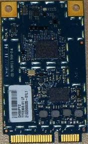
Click to zoom
Application Details
- Equipment Class
- PCB - PCS Licensed Transmitter
- Date of Grant
- Dec 26, 2011
- Application Purpose
- Original Equipment
- Date of Application
- Dec 15, 2011
- Equipment Note
- PCI Mini Card
- Frequency Range
- 1710.70000000 - 1754.30000000
- Company
- Inseego Corp.
- Country
- United States
Documents & Files
Document Text
Text extracted from the exhibit documents filed with the FCC. Open a document above to read the original.
Users Manual
Novatel Wireless Inc. Version 2.2 Page 1 of 20 Novatel Wireless, Inc. PCI Express Mini-card Installation Guidelines for E371 Version 2.2 Novatel Wireless Inc. Version 2.2 Page 2 of 20 Notice: Restricted Proprietary Information © Copyright Novatel Wireless, Inc. (2012) The information contained in this document is the exclusive property of Novatel Wireless, Inc. All rights reserved. Unauthorized reproduction of this manual in any form without the expressed written approval of Novatel Wireless, Inc. is strictly prohibited. This manual may not, in whole or in part, be copied, reproduced, translated, or reduced to any electronic or magnetic storage medium without the written consent of a duly authorized officer of Novatel Wireless Inc. The information contained in this document is subject to change without notice and should not be construed as a commitment by Novatel Wireless Inc. unless such commitment is expressly given in a covering document. Novatel Wireless Inc. makes no warranties, either expressed or implied, regarding this document, its merchantability, or its fitness, for any particular purpose. Printed and produced in United States of America. Novatel Wireless Inc. Version 2.2 Page 3 of 20 Document Revision History Rev. Date Brief Description of Change Originator Approved by 1.0 September 19, 2011 Initial Draft Todd Gallagher 2.0 November 14, 2011 Changes as requested during the FCC review. Roman Olmos Todd Gallagher 2.1 February 22, 2012 Update made to 1900MHz Antenna Gain Information Roman Olmos Todd Gallagher 2.2 February 24, 2012 Change to MPE limit in 824 band. Roman Olmos Todd Gallagher Novatel Wireless Inc. Version 2.2 Page 4 of 20 FCC KDB Publication Reference KDB Title Version Date Attachment Number Version Number SAR Evaluation Considerations for Laptop/Notebook and Tablet computers KDB 616217 11/13/2009 D03 V01 Mobile and Portable Device RF Exposure Procedures and Equipment Authorization Policies KDB 447498 11/13/2009 D01 V04 SAR Considerations for LTE Handsets and Data modems KDB 941225 12/15/2010 D05 V01 Modular Transmitter Approvals KDB 996369 07/12/2011 D01 V01r03 Permissive Change Policy KDB 178919 06/08/2011 D01 V05r01 Novatel Wireless Inc. Version 2.2 Page 5 of 20 E371 Module Installation and Collocation Guidelines for Host Devices 1.0 Introduction This document provides module and antenna installation guidelines for notebook computers to be authorized for use with the E371 module through the FCC Class I or Class II Permissive Change process. As the grantee Novatel Wireless is responsible for all integrations and must be consulted on all regulatory matters involving the E371. The module was originally granted by the FCC as a portable device with respect to RF Exposure compliance. This document outlines what RF Exposure considerations are required when integrating the E371 into a laptop type device for mobile or portable operation. For other basics and details about FCC RF exposure compliance requirements for mobile and portable devices, see FCC OET Bulletin 65 Supplement C. The following installation host configurations are addressed in this document. 1) The E371 module can be installed as a standalone transmitter in notebooks meeting the following conditions: a. Mobile device notebooks where >20cm separation distance is provided between the E371 transmitting antenna and the end user. The technical parameters for mobile measurements are defined in Section 2.1.1. b. Portable device notebooks where the separation distance is <20cm to ≥2.5cm provided between the E371 transmitting antenna that meet the technical parameters defined in Section 2.1.2. These devices may not require SAR evaluation and are covered by the original FCC/IC application. c. Portable device notebooks where the separation distance is <2.5cm provided between the E371 transmitting antenna that meet the technical parameters defined in Section 2.1.3. Devices require SAR evaluation and consultation by the grantee (Novatel Wireless) is required. Note: 1. “Standalone” when referenced in this document is defined where a single transmitter is transmitting, as opposed to two or more transmitters transmitting simultaneously. 2. Mobile Device Definition - FCC defines as a transmitting antenna located at a distance greater than ≥20cm from the user. 3. Portable Device Definition - FCC defines as a transmitting antenna is located at a distance less than ≤20cm from the user. 2) Collocated transmitters that can operate simultaneously with the E371 module is only allowed if the technical requirements defined in Section 4.0 are satisfied. 3) Should end-user installation be available module/notebook Two-Way Authentication is required. Please contact Novatel Wireless for additional details. 4) The FCC and Industry Canada IDs must be permanently affixed on the exterior of the notebook or readily accessible under a panel or battery pack of the host device that cannot be separated from the host device itself. Novatel Wireless Inc. Version 2.2 Page 6 of 20 The label must state: • This device contains FCC ID: PKRNVWE371 • This device contains IC:3229A-E371 5) These installation guidelines are not applicable to non-notebook host devices or tablet PCs. The installation guidelines are applicable for notebook computers where the E371 antennas and collocated antennas are located in the display portion of a notebook computer. SAR evaluation is completed with the display open at a ninety-degree angle as defined in KDB pub 616217 and Section 4 of KDB pub 447498. 6) These guidelines do not apply to devices that require power reduction to meet SAR limits. These integrations must be coordinated directly through Novatel Wireless. Novatel Wireless Inc. Version 2.2 Page 7 of 20 2.0 Module Installation Guidelines This section defines host installation limitations for mobile device and portable device hosts. 2.1.1 Mobile Device Hosts (WWAN to user separation distance >20cm) 2.1 Installation Guidelines The E371 module can be installed for …
Text truncated - open the document above for the full version.
Cover Letter(s)
Request for Modular Approval – FCC ID: PKRNVWE371 Item Requirements EUT Compliance 1 The module has its own RF shielding Meets requirements. 2 The module must have buffered modulation/data input(s) to ensure that the module will comply with FCC Part 15 requirements with any type of input signal. Meets requirements. 3 The module has its own power supply regulation. Meets requirements. 4 The module must contain a permanently attached antenna, or contain a unique antenna connector, and be marketed and operated only with specific antenna(s) per Sections 15.203, 15.204(b), 15.212(a), 2.929(b). Meets requirements. 5 The module must demonstrate compliance in a stand-alone configuration Meets requirements. 6 The module must be labeled with its permanently affixed FCC ID label, or use an electronic display Meets requirements. 7 The module must comply with all specific rules applicable to the transmitter. The grantee must provide comprehensive instructions to explain compliance requirements Meets requirements. 8 The module must comply with RF exposure requirements. If SAR compliance can only be demonstrated in specific host types or platforms, then the module type must be “limited.” Meets requirements. Sincerely, Roman Olmos Sr. Regulatory Technologist Novatel Wireless Inc.
Cover Letter(s)
Federal Communications Commission Equipment Authorization Division 7345 Oakland Mills Road Columbia, Maryland 21046 Subject: MPR Attestation FCC Certification No: PKRNVWE371 Novatel Wireless declares the following: 1) The LTE Maximum Power Reduction (MPR) is a mandatory feature that is built- in by the design. The feature is permanent and cannot be changed by the end user or the network operators. 2) The LTE MPR meets the applicable 3GPP TS 36.101 technical specification requirements (Table 6.2.3-1). MPR targets and maximum output power is permanently limited for the configurations specified in this table: Modulation Channel Bandwidth/transmission Bandwidth Configuration (RB) MPR (dB) Target MPR (dB) 1.4 MHz 3.0 MHZ 5 MHz 10 MHz 15 MHz 20 MHz QPSK > 5 > 4 > 8 > 12 > 16 > 18 1 ≤ 1 16QAM ≤ 5 ≤ 4 ≤ 8 ≤ 12 ≤ 16 ≤ 18 1 ≤ 1 16QAM > 5 > 4 > 8 > 12 > 16 > 18 2 ≤ 2 3) The device was tested for SAR with A-MPR disabled 4) The device cannot transmit as a higher power than identified in the Tune up procedures. Sincerely, Roman Olmos Sr. Regulatory Technologist Novatel Wireless Inc. LTE Band Class Bandwidth (MHz) 17 5, 10 4 1.4, 3, 5, 10, 15, 20
Cover Letter(s)
Date: September 13, 2011 Federal Communications Commission Equipment Authorization Division, Application Processing Branch 7435 Oakland Mills Road Columbia, MD 21048 Subject: Request for Confidentiality FCC ID: PKRNVWE371 To Whom It May Concern: In accordance with 47CFR0.459, Novatel Wireless Inc. requests long term confidentiality for the following items 1. E371 BOM (Bill of Material) 2. E371 Tuning Procedure 3. E371 Schematics Diagrams 4. E371 Theory of Operation 5. E371 Block Diagram In accordance with 47CFR0.457 and 0.459, Novatel Wireless Inc. requests short-term confidentiality for 180 days on the following items 1. E371 External and Internal Photos 2. E371 Test photos 3. E371 Integration Guide These items contain detailed system and equipment description and related information about the product which Novatel Wireless Inc. considers to be proprietary, confidential, and a custom design which otherwise would not be released to the general public. Since this design is a basis from which future technological products will evolve, Novatel Wireless Inc. also feels that this information would be of benefit to its competitors, and that the disclosure of the information in these exhibits would give our competitors an unfair advantage in the market. Sincerely, Roman Olmos Sr. Regulatory Technologist Novatel Wireless Inc.
External Photos
Proprietary and Confidential NOVATEL WIRELESS, INC. 9645 Scranton Road, Suite 205, San Diego, CA 92121 Toll Free: 888.888.9231 Main: 858.812.3400 Fax: 858.812.3402 Internet: www.novatelwireless.com ISO 9001: 2000 Novatel Wireless Garter1 E371 Embedded Module Internal/External Illustration I.Top Side PCB External Internal II. Bottom Side PCB External Internal
ID Label/Location Info
LABEL ASSY, IMEI, PYTHON E371, GENERIC Part Number: DA.01019442 Rev 1 Chuck Morningstar Novatel Wireless, Inc. IMEI Example: “XXXXXXXXXXXXXXX” DataMatrix 18 X 18 ECC type: 200 18 mil 11.5 mm 24 mm Blank Label Stock 25015894 White 24 mm X 11.5 mm Model Type: “E371” Verdana 9pt Bold TEXT: “IC: 3229A-E371” “FCC ID:PKRNVWE371” Verdana 3 pt, Bold TEXT: “NOVATEL WIRELESS, INC.” Verdana 3 pt, Bold APR 17, 2011 Text: IMEI: XXXXXXXXXXXXXXX” IMEI of modem Verdana 4pt Bold TEXT: “MADE IN XXXXX” XXXXX is Country of origin Verdana 3 pt, Bold XXXXX A
ID Label/Location Info
Proprietary and Confidential NOVATEL WIRELESS, INC. 9645 Scranton Road, Suite 205, San Diego, CA 92121 Toll Free: 888.888.9231 Main: 858.812.3400 Fax: 858.812.3402 Internet: www.novatelwireless.com ISO 9001: 2000 Regulatory Label Location “FCC Label Placement”
Internal Photos
Proprietary and Confidential NOVATEL WIRELESS, INC. 9645 Scranton Road, Suite 205, San Diego, CA 92121 Toll Free: 888.888.9231 Main: 858.812.3400 Fax: 858.812.3402 Internet: www.novatelwireless.com ISO 9001: 2000 Novatel Wireless Garter1 E371 Embedded Module Internal/External Illustration I.Top Side PCB External Internal II. Bottom Side PCB External Internal
RF Exposure Info
FCC OET BULLETIN 65 SUPPLEMENT C 01-01 IEEE STD 1528:2003 RSS-102 Issue 4, March 2010 RSS-102 Supplementary Procedures (SPR)-001, January 1, 2011 IEC 62209-2:2010 SAR EVALUATION REPORT For PCI Express Mini Card MODEL: E371 FCC ID: PKRNVWE371 IC: 3229A-E371 REPORT NUMBER: 11U13889-12B1 ISSUE DATE: December 15, 2011 Prepared for NOVATEL WIRELESS INC. 9645 SCRANTON ROAD SUITE #205 SAN DIEGO, CA 92121 Prepared by COMPLIANCE CERTIFICATION SERVICES (UL CCS) 47173 BENICIA STREET FREMONT, CA 94538, U.S.A. TEL: (510) 771-1000 FAX: (510) 661-0888 REPORT NO: 11U13889-12B1 DATE: December 15 2011 FCC ID: PKRNVWE371 IC: 3229B-E371 Page 2 of 61 COMPLIANCE CERTIFICATION SERVICES (UL CCS) FORM NO: CCSUP4031B 47173 BENICIA STREET, FREMONT, CA 94538, USA TEL: (510) 771-1000 FAX: (510) 661-0888 This report shall not be reproduced except in full, without the written approval of CCS. Revision History Rev. Issue Date Revisions Revised By -- September 21, 2011 Initial Issue -- A October 5, 2011 Updated report based on reviewer’s comments. 1. Added Sec. 14.8 “Scaled SAR due to some of the plots with power drifts over 5% limit” 2. Updated uncertainty value from “5%” to “5.7%” of Output Power Variation - SAR drift, due to power drifts over 5%. 3. Added test reduction explanation in this report. Sunny Shih B December 8, 2011 Additional test with (E)GPRS mode Sunny Shih B1 December 15, 2011 - Added Phantom thickness and tolerance information in Sec. 10 - Added IC reference standard IEC 62209-2 Sunny Shih REPORT NO: 11U13889-12B1 DATE: December 15 2011 FCC ID: PKRNVWE371 IC: 3229B-E371 Page 3 of 61 COMPLIANCE CERTIFICATION SERVICES (UL CCS) FORM NO: CCSUP4031B 47173 BENICIA STREET, FREMONT, CA 94538, USA TEL: (510) 771-1000 FAX: (510) 661-0888 This report shall not be reproduced except in full, without the written approval of CCS. Table of Contents 1. Attestation of Test Results ............................................................................................................... 5 2. Test Methodology .............................................................................................................................. 6 3. Facilities and Accreditation .............................................................................................................. 6 4. Calibration and Uncertainty .............................................................................................................. 7 4.1. Measuring Instrument calibration.................................................................................................. 7 4.2. Measurement Uncertainty............................................................................................................. 8 5. Equipment Under Test ...................................................................................................................... 9 6. System Specifications ..................................................................................................................... 10 7. Composition of Ingredients for Tissue Simulating Liquids ......................................................... 11 8. Simulating Liquid Parameters ........................................................................................................ 12 9. Tissue Parameters Check results .................................................................................................. 13 10. System Verification ...................................................................................................................... 14 10.1. System Check Results ............................................................................................................ 15 11. SAR Measurement Procedures ................................................................................................... 16 12. Output Power Measurements...................................................................................................... 17 12.1. GSM/(E)GPRS850 & 1900 ..................................................................................................... 17 12.2. UMTS (WCDMA) Release99 .................................................................................................. 18 12.3. UMTS (WCDMA) HSDPA ....................................................................................................... 19 12.4. UMTS (WCDMA) HSPA (HSDPA & HSUPA) ......................................................................... 21 12.5. LTE Band 17 ........................................................................................................................... 23 12.6. LTE Band 4 ............................................................................................................................. 24 13. Test Configurations ..................................................................................................................... 28 13.1. Antenna Positioned Vertically ................................................................................................. 28 13.1. Antenna Positioned Horizontally ............................................................................................. 29 14. Summary of SAR Test Results .................................................................................................... 30 14.1. GPRS850 ................................................................................................................................ 30 14.2. GPRS1900 .............................................................................................................................. 30 14.3. UMTS (WCDMA) Band V ........................................................................................................ 31 14.4. UMTS (WCDMA) Band IV ....................................................................................................... 31 14.5. UMTS (WCDMA) Band II ......................................................................................................…
Text truncated - open the document above for the full version.
RF Exposure Info
Date: 8/31/2011 Test Laboratory: UL CCS SAR Lab B 1_Vertical Ant_Down Communication System: GPRS-FDD (TDMA, GMSK, 2 slot); Frequency: 836.6 MHz; Duty Cycle: 1:4.00037 Medium parameters used (interpolated): f = 836.6 MHz; σ = 0.983 mho/m; ε r = 55.117; ρ = 1000 kg/m 3 Phantom section: Flat Section Room Ambient Temperature: 24.0 deg. C; Liquid Temperature: 23.0 deg. C DASY5 Configuration: - Area Scan setting - Find Secondary Maximum Within: 2.0 dB and with a peak SAR value greater than 0.0012W/kg - Probe: EX3DV4 - SN3773; ConvF(8.67, 8.67, 8.67); Calibrated: 5/3/2011 - Sensor-Surface: 2.5mm (Mechanical Surface Detection) - Electronics: DAE4 Sn1258; Calibrated: 5/2/2011 - Phantom: ELI v5.0 (A); Type: QDOVA001BB; Serial: 1117 - Measurement SW: DASY52, Version 52.6 (2);SEMCAD X Version 14.4.5 (3634) GPRS 850 2 slots/Main_Ant_M-CH/Area Scan (71x71x1): Measurement grid: dx=15mm, dy=15mm Maximum value of SAR (interpolated) = 0.00794 mW/g GPRS 850 2 slots/Main_Ant_M-CH/Zoom Scan (5x5x7)/Cube 0: Measurement grid: dx=8mm, dy=8mm, dz=5mm Reference Value = 2.706 V/m; Power Drift = -0.21 dB Peak SAR (extrapolated) = 0.00966 W/kg SAR(1 g) = 0.00645 mW/g; SAR(10 g) = 0.00431 mW/g Maximum value of SAR (measured) = 0.00812 mW/g 0 dB = 0.0081mW/g Date: 8/31/2011 Test Laboratory: UL CCS SAR Lab B 2_Vertical Ant_Up Communication System: GPRS-FDD (TDMA, GMSK, 2 slot); Frequency: 836.6 MHz; Duty Cycle: 1:4.00037 Medium parameters used (interpolated): f = 836.6 MHz; σ = 0.983 mho/m; ε r = 55.117; ρ = 1000 kg/m 3 Phantom section: Flat Section Room Ambient Temperature: 24.0 deg. C; Liquid Temperature: 23.0 deg. C DASY5 Configuration: - Area Scan setting - Find Secondary Maximum Within: 2.0 dB and with a peak SAR value greater than 0.0012W/kg - Probe: EX3DV4 - SN3773; ConvF(8.67, 8.67, 8.67); Calibrated: 5/3/2011 - Sensor-Surface: 2.5mm (Mechanical Surface Detection (Locations From Previous Scan Used)), Sensor-Surface: 2.5mm (Mechanical Surface Detection) - Electronics: DAE4 Sn1258; Calibrated: 5/2/2011 - Phantom: ELI v5.0 (A); Type: QDOVA001BB; Serial: 1117 - Measurement SW: DASY52, Version 52.6 (2);SEMCAD X Version 14.4.5 (3634) GPRS 850 2 slots/Main_Ant_M-CH/Area Scan (71x71x1): Measurement grid: dx=15mm, dy=15mm Maximum value of SAR (interpolated) = 0.00561 mW/g GPRS 850 2 slots/Main_Ant_M-CH/Zoom Scan (5x5x7)/Cube 0: Measurement grid: dx=8mm, dy=8mm, dz=5mm Reference Value = 2.216 V/m; Power Drift = 0.20 dB Peak SAR (extrapolated) = 0.016 W/kg SAR(1 g) = 0.00596 mW/g; SAR(10 g) = 0.00293 mW/g Maximum value of SAR (measured) = 0.010 mW/g 0 dB = 0.010mW/g Date: 11/9/2011 Test Laboratory: UL CCS SAR Lab A 1_Horizontal Ant_UP Communication System: GPRS-FDD (2 slot); Frequency: 836.6 MHz; Duty Cycle: 1:4.00037 Medium parameters used (interpolated): f = 836.6 MHz; σ = 0.972 mho/m; ε r = 53.544; ρ = 1000 kg/m 3 Phantom section: Flat Section Room Ambient Temperature: 24.0 deg. C; Liquid Temperature: 23.0 deg. C DASY5 Configuration: - Area Scan setting - Find Secondary Maximum Within: 2.0 dB and with a peak SAR value greater than 0.0012W/kg - Probe: EX3DV4 - SN3749; ConvF(8.79, 8.79, 8.79); Calibrated: 12/13/2010 - Sensor-Surface: 2.5mm (Mechanical Surface Detection (Locations From Previous Scan Used)), Sensor-Surface: 2.5mm (Mechanical Surface Detection) - Electronics: DAE3 Sn500; Calibrated: 7/14/2011 - Phantom: ELI v4.0(A); Type: QDOVA001BB; Serial: 1119 - Measurement SW: DASY52, Version 52.6 (2);SEMCAD X Version 14.4.5 (3634) GPRS 850 2 slots/Area Scan (51x81x1): Measurement grid: dx=15mm, dy=15mm Info: Interpolated medium parameters used for SAR evaluation. Maximum value of SAR (interpolated) = 0.318 mW/g GPRS 850 2 slots/Zoom Scan (5x5x7)/Cube 0: Measurement grid: dx=8mm, dy=8mm, dz=5mm Reference Value = 18.243 V/m; Power Drift = 0.01 dB Peak SAR (extrapolated) = 0.397 W/kg SAR(1 g) = 0.285 mW/g; SAR(10 g) = 0.199 mW/g Info: Interpolated medium parameters used for SAR evaluation. Maximum value of SAR (measured) = 0.335 mW/g 0 dB = 0.330mW/g Date: 11/9/2011 Test Laboratory: UL CCS SAR Lab A 1_Horizontal Ant_UP Communication System: GPRS-FDD (2 slot); Frequency: 836.6 MHz; Duty Cycle: 1:4.00037 GPRS 850 2 slots/Z Scan (1x1x21): Measurement grid: dx=20mm, dy=20mm, dz=5mm Info: Interpolated medium parameters used for SAR evaluation. Maximum value of SAR (measured) = 0.317 mW/g Date: 11/9/2011 Test Laboratory: UL CCS SAR Lab A 2_Horizontal Ant_Down Communication System: GPRS-FDD (2 slot); Frequency: 836.6 MHz; Duty Cycle: 1:4.00037 Medium parameters used (interpolated): f = 836.6 MHz; σ = 0.972 mho/m; ε r = 53.544; ρ = 1000 kg/m 3 Phantom section: Flat Section Room Ambient Temperature: 24.0 deg. C; Liquid Temperature: 23.0 deg. C DASY5 Configuration: - Area Scan setting - Find Secondary Maximum Within: 2.0 dB and with a peak SAR value greater than 0.0012W/kg - Probe: EX3DV4 - SN3749; ConvF(8.79, 8.79, 8.79); Calibrated: 12/13/2010 - Sensor-Surface: 2.5mm (Mechanical Surface Detection (Locations From Previous Scan Used)), Sensor-Surface: 2.5mm (Mechanical Surface Detection) - Electronics: DAE3 Sn500; Calibrated: 7/14/2011 - Phantom: ELI v4.0(A); Type: QDOVA001BB; Serial: 1119 - Measurement SW: DASY52, Version 52.6 (2);SEMCAD X Version 14.4.5 (3634) GPRS 850 2 slots/Area Scan (51x81x1): Measurement grid: dx=15mm, dy=15mm Info: Interpolated medium parameters used for SAR evaluation. Maximum value of SAR (interpolated) = 0.182 mW/g GPRS 850 2 slots/Zoom Scan (5x5x7)/Cube 0: Measurement grid: dx=8mm, dy=8mm, dz=5mm Reference Value = 13.678 V/m; Power Drift = -0.02 dB Peak SAR (extrapolated) = 0.216 W/kg SAR(1 g) = 0.156 mW/g; SAR(10 g) = 0.108 mW/g Info: Interpolated medium parameters used for SAR evaluation. Maximum value of SAR (measured) = 0.182 mW/g 0 dB = 0.180mW/g Date: 11/9/2011 Test Laboratory: UL CCS SAR Lab A 2_Horizontal Ant_Down Communication System: GPRS-FDD (2 slot); Frequency: 836.6 MHz; Duty Cycle: 1:4.00037 GPRS 850 2 slots/Z Scan (1x1x21): Measurement grid: dx=20mm, dy=20mm, dz=5mm Info: Interpolated med…
Text truncated - open the document above for the full version.
RF Exposure Info
Date: 8/12/2011 Test Laboratory: UL CCS SAR Lab A 1_Vertical Ant_Down Communication System: GPRS-FDD (TDMA, GMSK, 2 slot); Frequency: 1880 MHz; Duty Cycle: 1:4.00037 Medium parameters used: f = 1880 MHz; σ = 1.525 mho/m; ε r = 52.26; ρ = 1000 kg/m 3 Phantom section: Flat Section Room Ambient Temperature: 24.0 deg. C; Liquid Temperature: 23.0 deg. C DASY5 Configuration: - Area Scan setting - Find Secondary Maximum Within: 2.0 dB and with a peak SAR value greater than 0.0012W/kg - Probe: EX3DV4 - SN3686; ConvF(6.99, 6.99, 6.99); Calibrated: 1/24/2011 - Sensor-Surface: 2.5mm (Mechanical Surface Detection (Locations From Previous Scan Used)), Sensor-Surface: 2.5mm (Mechanical Surface Detection) - Electronics: DAE4 Sn1239; Calibrated: 11/17/2010 - Phantom: ELI v4.0(B); Type: QDOVA001BB; Serial: 1099 - Measurement SW: DASY52, Version 52.6 (2);SEMCAD X Version 14.4.5 (3634) GPRS 1900 2 slots/Main_Ant_Ch-M/Area Scan (71x71x1): Measurement grid: dx=15mm, dy=15mm Maximum value of SAR (interpolated) = 0.019 mW/g GPRS 1900 2 slots/Main_Ant_Ch-M/Zoom Scan (5x5x7)/Cube 0: Measurement grid: dx=8mm, dy=8mm, dz=5mm Reference Value = 3.409 V/m; Power Drift = -0.07 dB Peak SAR (extrapolated) = 0.050 W/kg SAR(1 g) = 0.019 mW/g; SAR(10 g) = 0.010 mW/g Maximum value of SAR (measured) = 0.034 mW/g 0 dB = 0.030mW/g Date: 8/12/2011 Test Laboratory: UL CCS SAR Lab A 2_Vertical Ant_Up Communication System: GPRS-FDD (TDMA, GMSK, 2 slot); Frequency: 1880 MHz;Duty Cycle: 1:4.00037 Medium parameters used: f = 1880 MHz; σ = 1.525 mho/m; ε r = 52.26; ρ = 1000 kg/m 3 Phantom section: Flat Section Room Ambient Temperature: 24.0 deg. C; Liquid Temperature: 23.0 deg. C DASY5 Configuration: - Area Scan setting - Find Secondary Maximum Within: 2.0 dB and with a peak SAR value greater than 0.0012W/kg - Probe: EX3DV4 - SN3686; ConvF(6.99, 6.99, 6.99); Calibrated: 1/24/2011 - Sensor-Surface: 2.5mm (Mechanical Surface Detection (Locations From Previous Scan Used)), Sensor-Surface: 2.5mm (Mechanical Surface Detection) - Electronics: DAE4 Sn1239; Calibrated: 11/17/2010 - Phantom: ELI v4.0(B); Type: QDOVA001BB; Serial: 1099 - Measurement SW: DASY52, Version 52.6 (2);SEMCAD X Version 14.4.5 (3634) GPRS 1900 2 slots/Main_Ant_Ch-M/Area Scan (51x51x1): Measurement grid: dx=15mm, dy=15mm Maximum value of SAR (interpolated) = 0.049 mW/g GPRS 1900 2 slots/Main_Ant_Ch-M/Zoom Scan (5x5x7)/Cube 0: Measurement grid: dx=8mm, dy=8mm, dz=5mm Reference Value = 5.335 V/m; Power Drift = 0.17 dB Peak SAR (extrapolated) = 0.066 W/kg SAR(1 g) = 0.039 mW/g; SAR(10 g) = 0.024 mW/g Maximum value of SAR (measured) = 0.050 mW/g 0 dB = 0.050mW/g Date: 11/29/2011 Test Laboratory: UL CCS SAR Lab B 1_Horizontal Ant_UP Communication System: GPRS-FDD (TDMA, GMSK, 2 slot); Frequency: 1880 MHz; Duty Cycle: 1:4.00037 Medium parameters used: f = 1880 MHz; σ = 1.491 mho/m; ε r = 51.004; ρ = 1000 kg/m 3 Phantom section: Flat Section Room Ambient Temperature: 24.0 deg. C; Liquid Temperature: 23.0 deg. C DASY5 Configuration: - Area Scan setting - Find Secondary Maximum Within: 2.0 dB and with a peak SAR value greater than 0.0012W/kg - Probe: EX3DV4 - SN3773; ConvF(7.37, 7.37, 7.37); Calibrated: 5/3/2011 - Sensor-Surface: 2.5mm (Mechanical Surface Detection) - Electronics: DAE4 Sn1258; Calibrated: 5/2/2011 - Phantom: ELI v5.0 (A); Type: QDOVA002BB; Serial: 1120 - Measurement SW: DASY52, Version 52.6 (2);SEMCAD X Version 14.4.5 (3634) GPRS 1900 2 slots/Main_Ant_Ch-M/Area Scan (51x81x1): Measurement grid: dx=15mm, dy=15mm Maximum value of SAR (interpolated) = 0.470 mW/g GPRS 1900 2 slots/Main_Ant_Ch-M/Zoom Scan (5x5x7)/Cube 0: Measurement grid: dx=8mm, dy=8mm, dz=5mm Referen ce Value = 16.979 V/m; Power Drift = -0.19 dB Peak SAR (extrapolated) = 0.689 W/kg SAR(1 g) = 0.383 mW/g; SAR(10 g) = 0.211 mW/g Maximum value of SAR (measured) = 0.462 mW/g 0 dB = 0.460mW/g Date: 11/29/2011 Test Laboratory: UL CCS SAR Lab B 1_Horizontal Ant_UP Communication System: GPRS-FDD (TDMA, GMSK, 2 slot); Frequency: 1880 MHz; Duty Cycle: 1:4.00037 GPRS 1900 2 slots/Main_Ant_Ch-M/Z Scan (1x1x21): Measurement grid: dx=20mm, dy=20mm, dz=5mm Maximum value of SAR (measured) = 0.440 mW/g Date: 11/29/2011 Test Laboratory: UL CCS SAR Lab B 1_Horizontal Ant_DOWN Communication System: GPRS-FDD (TDMA, GMSK, 2 slot); Frequency: 1880 MHz;Duty Cycle: 1:4.00037 Medium parameters used: f = 1880 MHz; σ = 1.491 mho/m; ε r = 51.004; ρ = 1000 kg/m 3 Phantom section: Flat Section Room Ambient Temperature: 24.0 deg. C; Liquid Temperature: 23.0 deg. C DASY5 Configuration: - Area Scan setting - Find Secondary Maximum Within: 2.0 dB and with a peak SAR value greater than 0.0012W/kg - Probe: EX3DV4 - SN3773; ConvF(7.37, 7.37, 7.37); Calibrated: 5/3/2011 - Sensor-Surface: 2.5mm (Mechanical Surface Detection) - Electronics: DAE4 Sn1258; Calibrated: 5/2/2011 - Phantom: ELI v5.0 (A); Type: QDOVA002BB; Serial: 1120 - Measurement SW: DASY52, Version 52.6 (2);SEMCAD X Version 14.4.5 (3634) GPRS 1900 2 slots/Main_Ant_Ch-M/Area Scan (51x81x1): Measurement grid: dx=15mm, dy=15mm Maximum value of SAR (interpolated) = 0.352 mW/g GPRS 1900 2 slots/Main_Ant_Ch-M/Zoom Scan (5x5x7)/Cube 0: Measurement grid: dx=8mm, dy=8mm, dz=5mm Reference Value = 14.462 V/m; Power Drift = 0.03 dB Peak SAR (extrapolated) = 0.478 W/kg SAR(1 g) = 0.292 mW/g; SAR(10 g) = 0.169 mW/g Maximum value of SAR (measured) = 0.373 mW/g 0 dB = 0.370mW/g Date: 11/29/2011 Test Laboratory: UL CCS SAR Lab B 1_Horizontal Ant_DOWN Communication System: GPRS-FDD (TDMA, GMSK, 2 slot); Frequency: 1880 MHz;Duty Cycle: 1:4.00037 GPRS 1900 2 slots/Main_Ant_Ch-M/Z Scan (1x1x21): Measurement grid: dx=20mm, dy=20mm, dz=5mm Maximum value of SAR (measured) = 0.312 mW/g Date: 8/12/2011 Test Laboratory: UL CCS SAR Lab A 5_Horizontal Ant_Front Communication System: GPRS-FDD (TDMA, GMSK, 2 slot); Frequency: 1880 MHz; Duty Cycle: 1:4.00037 Medium parameters used: f = 1880 MHz; σ = 1.525 mho/m; ε r = 52.26; ρ = 1000 kg/m 3 Phantom section: Flat Section Room Ambient Temperature: 24.0 deg. C…
Text truncated - open the document above for the full version.
RF Exposure Info
Date: 8/31/2011 Test Laboratory: UL CCS SAR Lab B 1_Vertical Ant_Down Communication System: UMTS-FDD (WCDMA); Frequency: 836.6 MHz; Duty Cycle: 1:1 Medium parameters used (interpolated): f = 836.6 MHz; σ = 0.983 mho/m; ε r = 55.117; ρ = 1000 kg/m 3 Phantom section: Flat Section Room Ambient Temperature: 24.0 deg. C; Liquid Temperature: 23.0 deg. C DASY5 Configuration: - Area Scan setting - Find Secondary Maximum Within: 2.0 dB and with a peak SAR value greater than 0.0012W/kg - Probe: EX3DV4 - SN3773; ConvF(8.67, 8.67, 8.67); Calibrated: 5/3/2011 - Sensor-Surface: 2.5mm (Mechanical Surface Detection) - Electronics: DAE4 Sn1258; Calibrated: 5/2/2011 - Phantom: ELI v5.0 (A); Type: QDOVA001B…
Text truncated - open the document above for the full version.
Contact Information
Applicant
Roman Olmos(Sr. Staff Regulatory Engineer)
Technical Contact
Compliance Certification ServicesAliza Zaffar
[email protected](510) 771-1000
47173 Benicia Street · Fremont · United States
Non-Technical Contact
Compliance Certification ServicesAliza Zaffar
[email protected](510) 771-1000
Test Firm
Compliance Certification ServicesThu Chan
Technical Specifications
| # | Rule Parts | Frequency Range | Power Output | Emission | Tolerance |
|---|---|---|---|---|---|
| 13 | 27 | 1.71 GHz - 1.75 GHz | 836.00 mW | 1M08D7W | 2.5 ppm |
Other Applications from Inseego Corp.
PKRISGM4330
Jun 18, 2026Wireless Portable Hotspot
Equipment Class
CBE - Citizens Band End User DevicesPKRISGM4010
Jan 30, 2026Wireless Hotspot
Equipment Class
JBP - Part 15 Class B Computing Device Peripheral
PKRISGM3000D
Dec 21, 2022Wireless Hotspot
Equipment Class
NII - Unlicensed National Information Infrastructure TXPKRISGM3100
Jul 24, 2022Wireless Hotspot
Equipment Class
5GM - Part 30 Mobile TransmitterPKRISGM3000A
Jul 24, 2022Wireless Hotspot
Equipment Class
DTS - Digital Transmission System