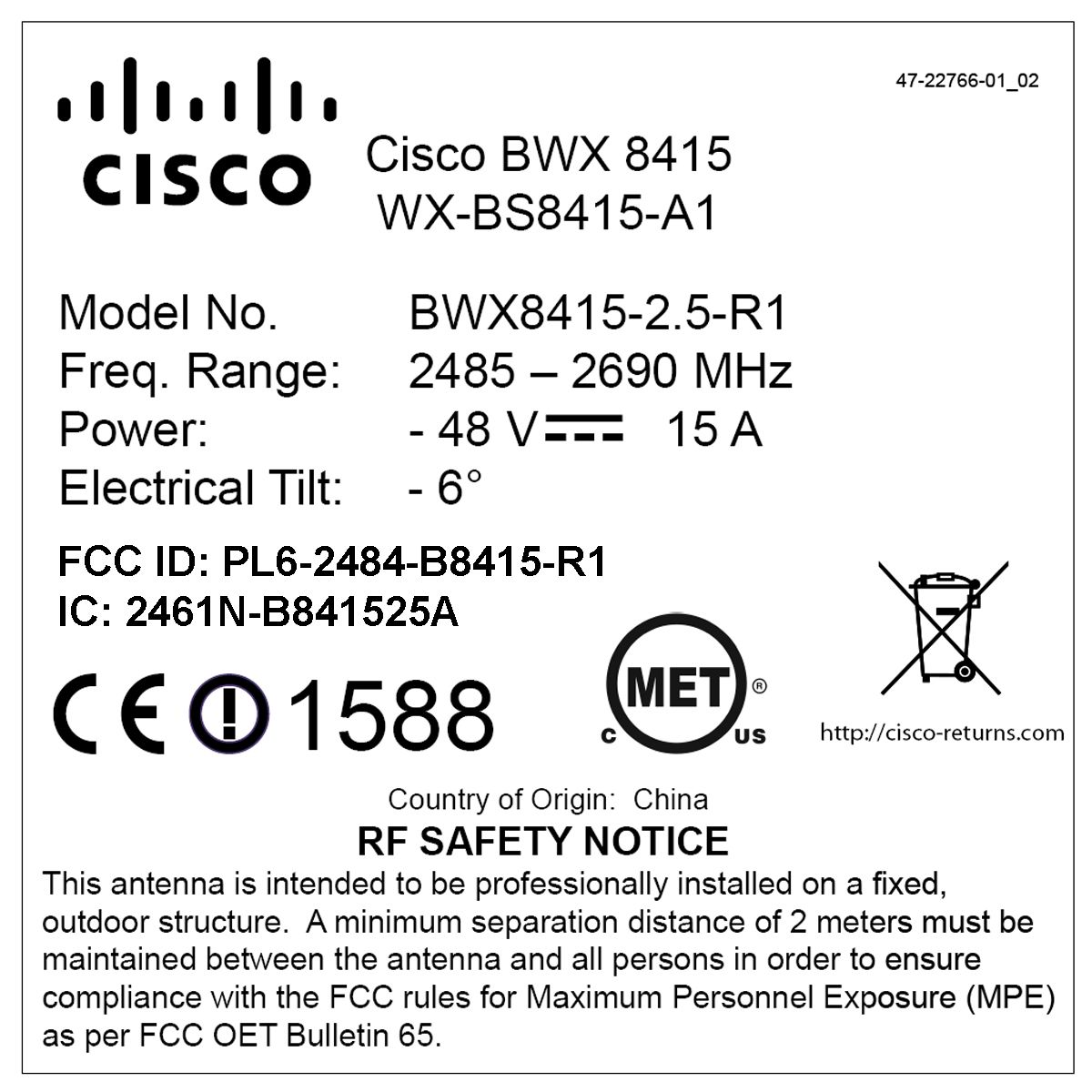
PL6-2484-B8415-R1WiMAX Base Station, Broadband Wireless, 2.5/2.6 GHz
Cisco Systems, Inc
Click to zoom
Application Details
- Equipment Class
- TNB - Licensed Non-Broadcast Station Transmitter
- Date of Grant
- Jan 27, 2010
- Application Purpose
- Original Equipment
- Date of Application
- Jan 27, 2010
- Equipment Note
- WiMAX Base Station, Broadband Wireless, 2.5/2.6 GHz
- Frequency Range
- 2501.25000000 - 2684.75000000
- Company
- Cisco Systems, Inc
- Country
- United States
Documents & Files
Document Text
Text extracted from the exhibit documents filed with the FCC. Open a document above to read the original.
Users Manual
PRELIMINARY Americas Headquarters Cisco Systems, Inc. 170 West Tasman Drive San Jose, CA 95134-1706 USA http://www.cisco.com Tel: 408 526-4000 800 553-NETS (6387) Fax: 408 527-0883 BWX 8415 Basestation Installation and Commissioning Guide October 30, 2009 Text Part Number: OL-19519-01 PRELIMINARY THE SPECIFICATIONS AND INFORMATION REGARDING THE PRODUCTS IN THIS MANUAL ARE SUBJECT TO CHANGE WITHOUT NOTICE. ALL STATEMENTS, INFORMATION, AND RECOMMENDATIONS IN THIS MANUAL ARE BELIEVED TO BE ACCURATE BUT ARE PRESENTED WITHOUT WARRANTY OF ANY KIND, EXPRESS OR IMPLIED. USERS MUST TAKE FULL RESPONSIBILITY FOR THEIR APPLICATION OF ANY PRODUCTS. THE SOFTWARE LICENSE AND LIMITED WARRANTY FOR THE ACCOMPANYING PRODUCT ARE SET FORTH IN THE INFORMATION PACKET THAT SHIPPED WITH THE PRODUCT AND ARE INCORPORATED HEREIN BY THIS REFERENCE. IF YOU ARE UNABLE TO LOCATE THE SOFTWARE LICENSE OR LIMITED WARRANTY, CONTACT YOUR CISCO REPRESENTATIVE FOR A COPY. The following information is for FCC compliance of Class A devices: This equipment has been tested and found to comply with the limits for a Class A digital device, pursuant to part 15 of the FCC rules. These limits are designed to provide reasonable protection against harmful interference when the equipment is operated in a commercial environment. This equipment generates, uses, and can radiate radio-frequency energy and, if not installed and used in accordance with the instruction manual, may cause harmful interference to radio communications.operation of this equipment in a residential area is likely to cause harmful interference, in which case users will be required to correct the interference at their own expense. The following information is for FCC compliance of Class B devices: The equipment described in this manual generates and may radiate radio-frequency energy. If it is not installed in accordance with Cisco’s installation instructions, it may cause interference with radio and television reception. This equipment has been tested and found to comply with the limits for a Class B digital device in accordance with the specifications in part 15 of the FCC rules. These specifications are designed to provide reasonable protection against such interference in a residential installation. However, there is no guarantee that interference will not occur in a particular installation. Modifying the equipment without Cisco’s written authorization may result in the equipment no longer complying with FCC requirements for Class A or Class B digital devices. In that event, your right to use the equipment may be limited by FCC regulations, and you may be required to correct any interference to radio or television communications at your own expense. You can determine whether your equipment is causing interference by turning it off. If the interference stops, it was probably caused by the Cisco equipment or one of its peripheral devices. If the equipment causes interference to radio or television reception, try to correct the interference by using one or more of the following measures: • Turn the television or radio antenna until the interference stops. • Move the equipment to one side or the other of the television or radio. • Move the equipment farther away from the television or radio. • Plug the equipment into an outlet that is on a different circuit from the television or radio. (That is, make certain the equipment and the television or radio are on circuits controlled by different circuit breakers or fuses.) Modifications to this product not authorized by Cisco Systems, Inc. could void the FCC approval and negate your authority to operate the product. The Cisco implementation of TCP header compression is an adaptation of a program developed by the University of California, Berkeley (UCB) as part of UCB’s public domain version of the UNIX operating system. All rights reserved. Copyright © 1981, Regents of the University of California. NOTWITHSTANDING ANY OTHER WARRANTY HEREIN, ALL DOCUMENT FILES AND SOFTWARE OF THESE SUPPLIERS ARE PROVIDED “AS IS” WITH ALL FAULTS. CISCO AND THE ABOVE-NAMED SUPPLIERS DISCLAIM ALL WARRANTIES, EXPRESSED OR IMPLIED, INCLUDING, WITHOUT LIMITATION, THOSE OF MERCHANTABILITY, FITNESS FOR A PARTICULAR PURPOSE AND NONINFRINGEMENT OR ARISING FROM A COURSE OF DEALING, USAGE, OR TRADE PRACTICE. IN NO EVENT SHALL CISCO OR ITS SUPPLIERS BE LIABLE FOR ANY INDIRECT, SPECIAL, CONSEQUENTIAL, OR INCIDENTAL DAMAGES, INCLUDING, WITHOUT LIMITATION, LOST PROFITS OR LOSS OR DAMAGE TO DATA ARISING OUT OF THE USE OR INABILITY TO USE THIS MANUAL, EVEN IF CISCO OR ITS SUPPLIERS HAVE BEEN ADVISED OF THE POSSIBILITY OF SUCH DAMAGES. CCDE, CCENT, Cisco Eos, Cisco Lumin, Cisco Nexus, Cisco StadiumVision, Cisco TelePresence, the Cisco logo, DCE, and Welcome to the Human Network are trademarks; Changing the Way We Work, Live, Play, and Learn and Cisco Store are service marks; and Access Registrar, Aironet, AsyncOS, Bringing the Meeting To You, Catalyst, CCDA, CCDP, CCIE, CCIP, CCNA, CCNP, CCSP, CCVP, Cisco, the Cisco Certified Internetwork Expert logo, Cisco IOS, Cisco Press, Cisco Systems, Cisco Systems Capital, the Cisco Systems logo, Cisco Unity, Collaboration Without Limitation, EtherFast, EtherSwitch, Event Center, Fast Step, Follow Me Browsing, FormShare, GigaDrive, HomeLink, Internet Quotient, IOS, iPhone, iQ Expertise, the iQ logo, iQ Net Readiness Scorecard, iQuick Study, IronPort, the IronPort logo, LightStream, Linksys, MediaTone, MeetingPlace, MeetingPlace Chime Sound, MGX, Networkers, Networking Academy, Network Registrar, PCNow, PIX, PowerPanels, ProConnect, ScriptShare, SenderBase, SMARTnet, Spectrum Expert, StackWise, The Fastest Way to Increase Your Internet Quotient, TransPath, WebEx, and the WebEx logo are registered trademarks of Cisco Systems, Inc. and/or its affiliates in the United States and certain other countries. All other trademarks mentioned in this document or Website are the property of their respective owners. The use of the word p…
Text truncated - open the document above for the full version.
Users Manual
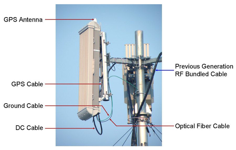
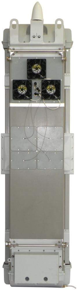
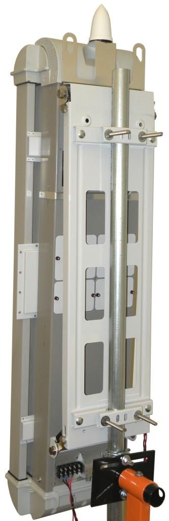
CHAPTER PRELIMINARY 6-1 BWX 8415 Basestation Installation and Commissioning Guide OL-19519-01 6 Installation 6.1 Inventory The first thing an installer physically does once onsite is to check to see that all equipment and materials have arrived, as well as to make sure all necessary documents and forms are available. 6.2 BWX 8415 Basestation Radio Unit (RU) Installation 6.2.1 Overview CautionOnly trained and qualified personnel should be allowed to install, replace, or service this equipment. Statement 1030 Caution- Refer installation and service to qualified service personnel only. No user serviceable parts inside. - Installation must be done in accordance with the instructions contained in this manual. - Read these instructions before installing. - Save these instructions. WarningInstallation of the equipment must comply with local and national electrical codes. Statement 1074 The Radio Unit (RU) is a lightweight unit that connects easily with the Antenna Unit (AU) to form the complete BWX 8415 Basestaion (BS). All customer accessible connectors will be located on the bottom of the RU ( Figure 6-1). Note that the circuit cards inside the BS are not field replaceable. Therefore, if a severe fault occurs, the entire unit is removed and replaced. The design intent is to cut down on the time it takes to troubleshoot or otherwise have a field support person onsite. PRELIMINARY 6-2 BWX 8415 Basestation Installation and Commissioning Guide OL-19519-01 Chapter 6 Installation 6.2.1 Overview Figure 6-1BWX 8415 RU Connectors The fiber-optic port, console port (RJ-45 connector), GPS antenna port, and the DC power connections (two -48V, 2 RTN, and one GND) are located on the bottom of the RU. WarningAt no time should a field person remove the RU’s cover or otherwise open the unit. In fact, doing so may void the warranty. GPS Antenna Port (Type N, female) DC Power (RTN/RTN/-48V/-48V/GND) Console Port (RJ-45, Engineering use only) Fiber-optic Port ( Amphenol Connector) GPS Antenna Port (Type N, female) GPS Antenna Port (Type N, female) DC Power (RTN/RTN/-48V/-48V/GND) DC Power (RTN/RTN/-48V/-48V/GND) Console Port (RJ-45, Engineering use only) Console Port (RJ-45, Engineering use only) Fiber-optic Port ( Amphenol Connector) Fiber-optic Port ( Amphenol Connector) PRELIMINARY 6-3 BWX 8415 Basestation Installation and Commissioning Guide OL-19519-01 Chapter 6 Installation 6.2.2 BWX 8415 Basestation Radio Unit Field Testing 6.2.2 BWX 8415 Basestation Radio Unit Field Testing THIS SECTION WAS WRITTEN/DEVELOPED, BASED ON THE FIELD TEST KIT LIST OF MATERIALS AND VERBAL DESCRIPTIONS OF HOW THE FIELD TEST KIT IS INTENDED TO BE USED. ONCE THE FIELD TEST KIT IS DEVELOPED, THIS SECTION WILL BE UPDATED TO REFLECT THE ACTUAL EQUIPMENT. It is recommended that the RU be tested, to ensure that the unit is functioning properly, prior to installation into the AU. Perform the following steps to connect the RU to the Field Test kit and test the RU. Step 1Connect the RU to the Fan/Cal Board assembly. Refer to Figure 6-2. - Connect the RU to the fans/cooling system - Connect the RU to the Cal board (using the 9 RF cables included in the Field Test kit) - Connect the GPS antenna to the GPS Antenna port on the bottom of the RU. Figure 6-2RU to Fan/Cal Board Assembly Connection Step 2Connect a ground cable to the RU ground. Tighten the nuts to 48 in. lbs. (5.4 Nm). Refer to Figure 6-3. Step 3Connect the DC power cable leads (2 RTN and 2 -48V) to the RU. Tighten the nuts to 48 in. lbs. (5.4 Nm). Refer to Figure 6-3. Figure 6-3Ground Cable and DC Power Cable Connections Step 4Connect an RJ-45-to-DB-9 serial cable to the Console port on the RU and to the Field Technician’s laptop PC. - Using a terminal application (such as TeraTerm or Hyperterminal), set the following port parameters: Baud Rate: 9600 Data: 8 bit Parity: None Stop: 1 bit Flow Control: None Step 5Power up the RU by connecting the DC power cable to a DC power source (48V power supply). NoteOnce the RU is powered up, it will begin to boot. The boot process can be monitored from the terminal application on the laptop PC. Step 6Modify the bootline parameters as necessary. (MORE DETAILS ONCE FIELD TEST KIT IS AVAILABLE) PRELIMINARY 6-4 BWX 8415 Basestation Installation and Commissioning Guide OL-19519-01 Chapter 6 Installation 6.2.3 Install the Radio Unit Step 7Once the bootup is completed, perform a calibration to verify the RU is functioning properly. (MORE DETAILS ONCE FIELD TEST KIT IS AVAILABLE) Step 8After the calibration has been completed successfully, power down the RU. Disconnect the RU from the DC power source. Step 9Disconnect the ground cable and DC power leads from the RU. Step 10Disconnect the RF cables and GPS cable from the RU. Step 11Disconnect the fans/cooling system. 6.2.3 Install the Radio Unit WarningDo not work on the system or connect or disconnect cables during periods of lightning activity. Statement 1001 WarningEnsure that the power to the RU unit is OFF before installing the unit into the AU. Step 1Remove the two lower faceplate covers on the back of the AU, to access the RF calibration board and RF cable connectors. Refer to Figure 6-4. Figure 6-4Faceplate Covers Removed CautionDo not attempt to insert the RU into the AU without removing the lower faceplate covers. These faceplate covers have a mechanical interlock pin, which inserts into the RU, and if the faceplate covers are not removed when inserting the RU, damage could occur to the RU and the mechanical interlock pins. Step 2Insert the RU into the AU, as shown in Figure 6-5. RF Calibration BoardMechanical Interlock Pin Holes PRELIMINARY 6-5 BWX 8415 Basestation Installation and Commissioning Guide OL-19519-01 Chapter 6 Installation 6.2.3 Install the Radio Unit Figure 6-5Inserting the RU into the AU Step 3Connect the RF cables and the Cal cable, coming from the RF calibration board, to the RF connectors and Cal connector on the RU unit. Step 4Replace the faceplate covers. Be sure to ins…
Text truncated - open the document above for the full version.
Users Manual
PRELIMINARY 6-17 BWX 8415 Basestation Installation and Commissioning Guide OL-19519-01 Chapter 6 Installation 6.3.6 Rooftop Antenna Placement Tool 6.3.6 Rooftop Antenna Placement Tool Reference: Rooftop Antenna Placement Tool This is a picture of the worksheet in the Antenna Placement Tool for a quick visual identification Figure 6-17); this appendix does not include the entire tool. Please use the electronic copy of the tool to datafill the site information. This form can be found on the following LiveLink site: https://tools.cisco.com/cws/livelink?func=ll&objid=4353291&objaction=browse The Tool is updated periodically. If you are not sure that you have the latest version, please contact Cisco Technical Services and request that the latest version of the tool be sent to you. Figure 6-17Rooftop Antenna Placement Tool PRELIMINARY 6-18 BWX 8415 Basestation Installation and Commissioning Guide OL-19519-01 Chapter 6 Installation 6.3.7 Set the Downtilt 6.3.7 Set the Downtilt Based on coverage objectives determined by previous RF planning, the AU may need adjusting upward or downward once mounted on the pole, tower, roof, building, or other structure. The panel antenna has a -6° built-in electrical downtilt. You will use an inclinometer to read the mounted position and to determine what adjustments, if any, need to be made. For example, if the inclinometer reads +2° (uptilt) and you are mounting an AU, the resulting beam has a –4° downtilt ( Figure 6-18). Figure 6-18Downtilt Adjustment Example The downtilt can be adjusted per the assembly shown in Figure 6-19 A p p a r e n t + 1 ° E f f e c t i v e – 5 ° Electr ical –6° A p p a r e n t + 1 ° E f f e c t i v e – 5 ° Electr ical –6° A p p a r e n t + 1 ° E f f e c t i v e – 5 ° Electr ical –6° The inclinometer reads +1 °(uptilt) A p p a r e n t + 1 ° E f f e c t i v e – 5 ° Electr ical –6° A p p a r e n t + 1 ° E f f e c t i v e – 5 ° Electr ical –6° A p p a r e n t + 1 ° E f f e c t i v e – 5 ° Electr ical –6° The panel antenna has a -6 °built in electrical downtilt The resulting beam has a -5 °downtilt A p p a r e n t + 1 ° E f f e c t i v e – 5 ° Electr ical –6° A p p a r e n t + 1 ° E f f e c t i v e – 5 ° Electr ical –6° A p p a r e n t + 1 ° E f f e c t i v e – 5 ° Electr ical –6° The inclinometer reads +1 °(uptilt) A p p a r e n t + 1 ° E f f e c t i v e – 5 ° Electr ical –6° A p p a r e n t + 1 ° E f f e c t i v e – 5 ° Electr ical –6° A p p a r e n t + 1 ° E f f e c t i v e – 5 ° Electr ical –6° The panel antenna has a -6 °built in electrical downtilt The resulting beam has a -5 °downtilt PRELIMINARY 6-19 BWX 8415 Basestation Installation and Commissioning Guide OL-19519-01 Chapter 6 Installation 6.3.8 Antenna Orientation Figure 6-19Downtilt Adjustment Assembly 6.3.8 Antenna Orientation The magnetic declination, which is the angular difference between observed magnetic north on a compass and geographic (or “true”) north, shifts from year to year. Panel antennas must be oriented appropriately as required by the RF plan. Adjustments that will need to be made are based on the Magnetic Declination Chart (Figure 6-20), which provides values to correct the compass reading and determine the true geographic East. Always check for the latest chart information, which may be found at the following web address: www.thecompassstore.com/decvar.html. Since this is not the year 2000 any more, you will want to check this reference chart to learn how your magnetic declination may have shifted since then. Notice that the map measures annual shifts in minutes. Since it takes 60 minutes to equal 1 degree, if you notice that your location has a declination shift of 5 minutes per year, this means it will be another 12 years before your declination adjustment changes by one whole degree. Downtilt Adjustment Bracket Bolts PRELIMINARY 6-20 BWX 8415 Basestation Installation and Commissioning Guide OL-19519-01 Chapter 6 Installation 6.4 Power and Ground Cabling Figure 6-20Magnetic Declination Chart – Example NoteIt is better to convert the “true” azimuth (which way the antenna should point in the horizontal plane) as required by the RF Plan to the magnetic value that will be read on the compass before sending the installer to the field. This way the installer will go by the reading on the compass, not having to worry about magnetic declination corrections. 6.4 Power and Ground Cabling 6.4.1 Overview The BS will operate at an input voltage of - 48 V DC, as measured at the input terminals to the BS. General power and grounding information was covered in Chapter 5, “Pre-installation.” Please refer there for information about power and ground cabling. 6.4.2 System Ground Cabling The BS must be grounded prior to connecting power. WarningThis equipment must be externally grounded using the supplied ground wire before power is applied. Contact the appropriate electrical inspection authority or an electrician if you are uncertain that suitable grounding is available. Statement 366 Use a compass to determine the magnetic East Use a Magnetic Declination chart to correct the compass reading and determine the true geographic East World Magnetic Declination Chart - Year 2000 Unit:Degrees World Magnetic Declination Chart - Year 2000 Unit:Degrees PRELIMINARY 6-21 BWX 8415 Basestation Installation and Commissioning Guide OL-19519-01 Chapter 6 Installation 6.4.2 System Ground Cabling WarningRead the installation instructions before connecting the system to the power source. Statement 1004 WarningWhen installing or replacing the unit, the ground connection must always be made first and disconnected last. Statement 1046 NoteIt is strongly recommended that no switch or disconnect device be installed in the ground cabling. In all installations and when powering the BS, you must follow these instructions to properly ground the BS: Step 1Strip the insulation as required for the grounding lug. Step 2Use the appropriate crimping tool to crimp the supplied 6-AWG grounding lug to th…
Text truncated - open the document above for the full version.
Users Manual
CHAPTER PRELIMINARY 7-1 BWX 8415 Basestation Installation and Commissioning Guide OL-19519-01 7 Commissioning 7.1 Install the Element Management System (EMS) References: •BWX EMS Overview Manual •BWX EMS Software Installation Guide •BWX Mobile WiMAX Configuration Guide 7.1.1 ‘Setup the ‘Test’ EMS Before installing the EMS software on a local computer, it is a good idea to check the customer’s network architecture plan. You should review the plan against the actual setup at the site, checking to see that all equipment and software are installed and available for use. Verify that all routers are installed and IP addresses are correct. You will need a “test” EMS computer in order to enter some basic configuration data needed to test the system once it is powered on. As an installer, you can either use a laptop computer or the customer’s intended EMS Server. (If you use the customer’s intended EMS Server, it will be connected through the backhaul, which is a fiber optic connection between the BWX 8415 Basestation (BS) and the service provider’s network.) Typically, in order to keep a constant link, a 10/100 Base-T Ethernet hub or switch connects the test EMS to the BS Data port using an Ethernet cable. This allows the technician to use the EMS Client to communicate with the EMS Server, which are installed on the same test computer (instructions later in this chapter). An RS-232 serial cable is then connected between the test EMS and the Console port on the BS. Using standard communication software -- i.e., a terminal emulation program, such as Windows HyperTerm or TeraTerm -- allows the installer to enter basic configuration data at this early stage. The procedure for setting up the communications software is described below. PRELIMINARY 7-2 BWX 8415 Basestation Installation and Commissioning Guide OL-19519-01 Chapter 7 Commissioning 7.1.2 Setting Up Direct Communications Software 7.1.2 Setting Up Direct Communications Software Step 1Verify that the fiber optic cable going to the BS is securely connected to the proper port on the backhaul network. Step 2Connect an Ethernet cable between the backhaul network and the Ethernet connector on the PC that will be used as the test EMS. NoteA VT 100 terminal or any standard Windows-based ASCII terminal emulation program can be used for connecting to the BS. The connection for HyperTerm is explained here as an illustrative example. The steps to get to the HyperTerm program may be different due to variances between Operating Systems and in the PC setup. There have been cases of extra “garbage” data while using the HyperTerm program. The preferred TeraTerm program can be downloaded free from the Internet. Step 3Power on the test EMS Server. Step 4On the PC, go to Start > Programs > Accessories > Communications > HyperTerminal. Step 5In the COM1 Properties window (Figure 7-1), under the Port settings tab enter the configuration options. Click “OK”. Figure 7-1COM1 Properties Bits per second: 9600 Data Bits: 8 Parity: None Stop Bits: 1 Flow Control: None Bits per second: 9600 Data Bits: 8 Parity: None Stop Bits: 1 Flow Control: None PRELIMINARY 7-3 BWX 8415 Basestation Installation and Commissioning Guide OL-19519-01 Chapter 7 Commissioning 7.1.3 Install the BWX EMS Software and Start & Configure the BWX EMS Server 7.1.3 Install the BWX EMS Software and Start & Configure the BWX EMS Server 7.1.3.1 Install the BWX EMS Software Please refer to the BWX EMS Software Installation Guide for minimum computing requirements and instructions to load the software. When you load the EMS software into the CiscoEMS\ directory on the computer, the file structure will look something like what is shown in Figure 7-2. This is a Windows example. NoteThis is the directory when you install the Server. The directory when you install the Client is different. Figure 7-2BWX EMS Server Software Directory (in a Windows PC) Be sure to select the correct instructions for your server – based on operating system, either Windows ® or Unix ® . You will need to install both the Server and Client applications (Figure 7-3). Be sure to check the latest software Release Notes for updated information and procedures for the version of software you are loading. Figure 7-3BWX EMS Server & Client Applications <EMS Install Directory> <Ftp Server Root Path> <BTS/CPE SW Ftp Directory> sw<BTS/CPE SW Ftp Directory> sw load files should be placed here <Perf Log Storage Directory> <Perf Log Storage Directory> online documentationonline documentation log files are stored herelog files are stored here script files for CLI should be placed herescript files for CLI should be placed here databasedatabase configuration filesconfiguration files executable filesexecutable files database-related Java archive (jar) filesdatabase-related Java archive (jar) files Corba-related filesCorba-related files Java runtime filesJava runtime files EMS jar fil esEMS jar fil es <EMS Install Directory> <Ftp Server Root Path> <BTS/CPE SW Ftp Directory> sw<BTS/CPE SW Ftp Directory> sw load files should be placed here<BTS/CPE SW Ftp Directory> sw<BTS/CPE SW Ftp Directory> sw load files should be placed here <Perf Log Storage Directory> <Perf Log Storage Directory><Perf Log Storage Directory><Perf Log Storage Directory> online documentationonline documentationonline documentationonline documentation log files are stored herelog files are stored herelog files are stored herelog files are stored here script files for CLI should be placed herescript files for CLI should be placed herescript files for CLI should be placed herescript files for CLI should be placed here databasedatabasedatabasedatabase configuration filesconfiguration filesconfiguration filesconfiguration files executable filesexecutable filesexecutable filesexecutable files database-related Java archive (jar) filesdatabase-related Java archive (jar) filesdatabase-related Java archive (jar) filesdatabase-related Java archive (jar) files Corba-related filesCorba-related fil…
Text truncated - open the document above for the full version.
Users Manual
PRELIMINARY D-1 BWX 8415 Basestation Installation and Commissioning Guide OL-19519-01 APPENDIX D RF Center Frequency and Interference Analysis Guidelines Reference: RF Center Frequency and Interference Analysis These guidelines are intended for an experienced and Cisco qualified specialist Field Engineer to gather data for RF Engineering purposes. The procedures that are described are performed in order to make a determination of basestation center frequency and possible interference points. Please refer to all regulatory information for your region prior to performing these procedures. Before You Start Overview An RF interference analysis is usually called for under two conditions. One is when it is used for evaluating a candidate BWX 8415 Basestation (BS) site prior to deployment of equipment. We refer to the interference testing under these circumstances as a Pre-installation Test. The second is the Post-installation Test, when data is collected to determine (a) if there is any interference in the area at all; or (b) the source, or cause, of known interference in the area of the installed and operational site. As is obvious from the name of this test, it occurs after the basestation has been deployed and turned up. The instructions in this document assume the Field Engineer is at the BS site where the testing will take place. The data the Field Engineer gathers using the Interference Sweep procedure in this document will be evaluated and used in the calibration of the basestation. The data will help verify and plan for noise in the area. To get the most benefit from this procedure, we suggest you follow these high-level steps: Step 1: Read the entire procedure. Step 2: Choose the correct Test configuration setup, per this procedure. Step 3: Perform the Interference Sweep procedure. Step 4: Send the results to Cisco or your RF Engineer. PRELIMINARY D-2 BWX 8415 Basestation Installation and Commissioning Guide OL-19519-01 Appendix D RF Center Frequency and Interference Analysis Guidelines Spectrum Analyzer Settings Required Equipment You will need the equipment shown in Tab l e D-1 to complete the interference testing. Ta b l e D-1Required Equipment Spectrum Analyzer Settings There are two types of interference tests conducted under either the Pre-installation or Post-installation situation: Frequency Domain test and Time Domain test. The following section explains some specific settings on the Spectrum analyzer, and what effects they will have on these tests. Frequency Domain Test The Frequency Domain test is a measurement of the amplitude of an incoming signal across a given frequency span. Setup for the Spectrum Analyzer: •Frequency = the channel to be tested (refer to frequency charts later in procedure) •Bandwidth (BW) = 100 KHz or lower •Reference Level = –50 dBm •Attenuation = 0 dB •Preamp, if available = on •Span = determined by the start and stop frequencies For the Frequency Domain test, the two parameters most frequently configured incorrectly are Reference Level and Bandwidth. To help the user determine the best settings, this section gives a short description as to what changes will be seen on the display if the parameter is changed. EquipmentComments HP4404B, FSH3, or FSH6 Spectrum Analyzer (or equivalent) NOTE 1: If checking for 3.4/3.5 GHz spectrum, make sure the Spectrum Analyzer reads up to 4 GHz. NOTE 2: An equivalent analyzer must have the following functions: Screen Save abilities, Max-hold function, Peak search, and ability to operate in the required frequency range BWX Basestation Antenna Test Box QMA, N Type Connectors, and different RF cables to make the connections Test antenna in the given frequency rangeCisco BWX Basestation Antenna LNA in the given frequency range- With a standard antenna you need an additional 30 dB of gain PRELIMINARY D-3 BWX 8415 Basestation Installation and Commissioning Guide OL-19519-01 Appendix D RF Center Frequency and Interference Analysis Guidelines Spectrum Analyzer Settings Reference Level This parameter sets the level of the top line of the Spectrum analyzer display (Figure D-1). Figure E-1 shows a display with the reference level set to –50 dB and the noise floor at –104 dB. The Blue line is a display line showing a level of –103.9 dB. As you can see, the top-level line displays –50dB. On most Spectrum Analyzers the RF noise floor is coupled with the Reference Level line. A Spectrum Analyzer will try and display the noise floor on screen. If the reference level is set at a level that is too high for the Spectrum Analyzer to display the noise floor, it will automatically change the displayed level for the noise floor ( Figure D-2). Figure D-1-50 Reference Level l PRELIMINARY D-4 BWX 8415 Basestation Installation and Commissioning Guide OL-19519-01 Appendix D RF Center Frequency and Interference Analysis Guidelines Spectrum Analyzer Settings Figure D-2-10 Reference Level Bandwidth Figure D-2 shows a reference level setting that was manually raised in the Spectrum Analyzer to –10. The blue line is the display line that was set with the original noise floor at the –50 reference level. When the reference level was raised from –50 to –10 the displayed noise floor also raised approximately 25 dB By setting the reference level to a lower value, the Spectrum Analyzer is able to display a noise floor that is closer to the actual digital noise floor of the equipment. Figure D-3 and Figure D-4 show the reason the reference level is important for capturing data for interference measurements. In Figure D-3, the reference was set at –50 dB level. A –65 dB signal was injected into the Spectrum Analyzer. In Figure D-4 the same –65 dB signal level was injected into the Spectrum Analyzer, but the reference level was changed from –50 dB to –10 dB. Figure D-4 still shows the –65 dB signal but only at 18 above the noise floor; whereas Figure D-3 shows the –65 dB signal at 40 dB above the noise floor. While measuring interference, if the reference le…
Text truncated - open the document above for the full version.
Contact Information
Applicant
Gerard Thorpe(Manager , EMC Standards and Operations)
Technical Contact
Cisco Systems, Inc.Russell Leath
2200 East President George Bush Hwy · Richardson, Texas · United States
Non-Technical Contact
Cisco Systems, Inc.David Wolf
Test Firm
Cisco Systems, Inc.Dave Wilson
Technical Specifications
| # | Rule Parts | Frequency Range | Power Output | Emission | Tolerance |
|---|---|---|---|---|---|
| 2 | 27 | 2.50 GHz - 2.68 GHz | 45.4 W | 9M40W7D | 0.02 ppm |
Other Applications from Cisco Systems, Inc

PL6-2496-BTS3-R2
Mar 10, 2008BTS Transceiver
Equipment Class
TNB - Licensed Non-Broadcast Station Transmitter
PL6-2300-BTS3-R2
Mar 06, 2008BTS Transceiver
Equipment Class
TNB - Licensed Non-Broadcast Station Transmitter
PL6-2496-BTS4-R1
Mar 05, 2008BTS Transceiver
Equipment Class
TNB - Licensed Non-Broadcast Station Transmitter
PL6-2300-BTS4-R1
Mar 05, 2008BTS Transceiver
Equipment Class
TNB - Licensed Non-Broadcast Station Transmitter
PL6-2300-MDM90-S1
Aug 02, 2007CPE Transceiver
Equipment Class
TNB - Licensed Non-Broadcast Station Transmitter