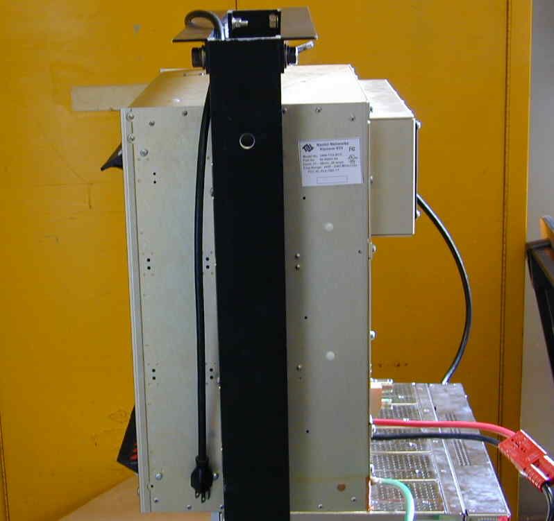
PL6-BTS-R3Broadband Data BTS
Cisco Systems, Inc
Click to zoom
Application Details
- Equipment Class
- TNB - Licensed Non-Broadcast Station Transmitter
- Date of Grant
- Jan 05, 2004
- Application Purpose
- Original Equipment
- Date of Application
- Jan 05, 2004
- Equipment Note
- Broadband Data BTS
- Frequency Range
- 2500.00000000 - 2596.00000000
- Company
- Cisco Systems, Inc
- Country
- United States
Documents & Files
Document Text
Text extracted from the exhibit documents filed with the FCC. Open a document above to read the original.
Users Manual
Navini Networks, Inc. Ripwave Base Station I&C Guide Part #40-00047-00 Rev F v1.0 (TTA) 109 October 23, 2003 Appendix A: Sample Statement of Work (SoW) The following is an example of a Statement of Work. The Statement of Work outlines the general activities that must be conducted in order to complete the installation and commissioning tasks for a Ripwave Base Station. Example: Statement of Work for Standard Installation Services The following statement of work will be used to outline the areas of responsibilities for the Navini Networks antenna (known as the RFS) and Base Station (known as the BTS) installations to be completed with Navini Networks Client (referred to as Client in this document). Client may choose to hire a contractor or tower crew to assist with its activities. Navini Networks has no formal contract relationship with the contractor, who will be managed by Client. The following work items are suggested content only - - final scope and terms to be negotiated directly with Client. Navini Networks support personnel will be on site for the entire installation and commissioning process, and will provide technical expertise, information, and recommendations with respect to site design and installation. It is recommended that contractor have a Non-Disclosure Agreement (NDA) in place with Client and Navini Networks prior to execution of work. Contractor shall not publicly disclose any information concerning this deployment or trial with any other parties, unless approved in writing in advance by Client and Navini Networks. Navini Networks 1. Provide Field Engineer to consult with Client and Contractor for planning efforts. Review Site design sketches and BOM prepared by others. 2. Review network architecture information (connection diagram and logical addresses) prior to start of installation. 3. Review Sweep results with Client and contractor. Sweep to be provided of RFS after shipment, of coax cables and RF path on tower, and of cables and RFS after installation, before power up. 4. Review AC and DC power system installation. Review DC power system test with Client and contractor. 5. Review backhaul circuit installation test results with Client. 6. Review GPS antenna and cable installations. 7. Review and Verify Cable and Antenna System Installation Work 8. Site walk with contractor and Client for Punchlist. 9. Load EMS software on Client supplied workstation, and verify connectivity to BTS. Ripwave Base Station I&C Guide Navini Networks, Inc. 110 Part #40-00047-00 Rev F v1.0 (TTA) October 23, 2003 10. Provide BTS installation – Chassis and Cards. 11. Apply power to BTS and perform all power up, BTS calibration verification checks, commissioning and initial testing of Navini Networks system. May use EMS on local laptop. 12. With assistance of Client, Perform Drive Test / Coverage Verification. 13. With assistance of Client, perform data rate testing at mutually specified locations – 15 for Omni, 5 for each panel RFS. 14. With client, integrate BTS into backhaul network and verify operation. 15. Closeout / Customer Acceptance package, including inventory of hardware. 16. Navini Networks to provide own tools and test equipment. 17. Clean job site daily. Client / Contractor Work Items 1. Perform Site survey at each site. 2. Prepare Installation sketch and Bill of Materials (BOM) for each site. Note that these are not sealed construction drawings. 3. Client / Contractor Site Design and Bid Walk. 4. Material Procurement. 5. Acquire building permits. 6. Inside Network cabling from demark to BTS rack 7. AC power installation (provide dedicated 115 VAC 20 A circuit for each BTS, dual outlet receptacle). 8. Air conditioning work or other hut electrical work. 9. 24 VDC rectifier installation, cabling to BTS chassis, cabling to AC circuit breaker. Test 24 VDC system (note: do not apply power to BTS). 10. Mount 19” TELCO rack inside hut (base anchors, or overhead brackets or both) 11. Provide core drilling and furnish and install feed through panel for coax cables, unless already existing. Seal holes using similar materials to other existing feed-through at each site. 12. Install grounding inside hut for rack and 24 VDC system. Install ground bus bar inside hut entry per drawings. Install ground bus bars on antenna structure and ground coax cables per sketch. 13. Install and apply coax cables and connectors. This includes main coax runs on tower, plus coax jumpers at antenna and at hut, as specified by drawings. Recommend and Install all cable hangers and supports, and grounding, per standard practice in use at tower location. Install surge protectors per design sketches and BOM. 14. Sweep test coax cables at designated sweep frequencies. 15. Install power and data cable from antenna to BTS. 16. Weather seal all outside connections. 17. Recommend, furnish and install mounting structure (arm assembly) to stand-off Navini RFS from tower. Standoff assembly to include pipe mount for antenna mount. Install Navini RFS on arm on tower. Connect to coax cables and provide sweep of cable / RFS assembly. Provide photographic documentation of tower top installation work. 18. Provide equipment and cable labeling as required. 19. Install (2) GPS antennas on ice bridge (or other agreed upon location). Furnish and install any required brackets or pipe mounts. Install GPS coax cables and connectors from GPS Navini Networks, Inc. Ripwave Base Station I&C Guide Part #40-00047-00 Rev F v1.0 (TTA) 111 October 23, 2003 antenna to BTS. 20. Site walk at completion with Client and Navini, create Punchlist; clear applicable punchlist items. 21. Arrange disposal of trash 22. Provide RF coverage analysis plots before start of installation. Provide model tuning, if required. 23. Provide architecture document before start of installation, including connection diagram and logical network element assignments (IP addresses, PVCs, etc.). 24. Set Up and Verify all network equipment and backhaul circuits. 25. Set Up and Ver…
Text truncated - open the document above for the full version.
Users Manual
Navini Networks, Inc. Ripwave Base Station I&C Guide Part #40-00047-00 Rev F v1.0 (TTA) 181 October 23, 2003 Appendix O: RFS System Test (Cable Sweeps) Introduction Before installing the Base Station at a site, the RFS and the associated cables must be tested, and the results of the tests documented. This procedure applies to the full RFS sub-assembly and associated cables: data/power cable, RF cables, and the RFS unit. All results are recorded in the RFS System Test Form P/N 40-00093-00. Procedures – Combo & Split Chassis Base Stations RFS Data/Power Cable (Combo and Split BTS Configurations Only) This test will check the integrity of the data/power cable. The cable being tested consists of six twisted pairs of conductors. The conductors will be tested for continuity, opens, and shorts. Male connectors are on both ends of the cable. Each connector is wired the same. You will need to check all cables – the main cable from the RFS to the data/power cable surge protector, and the jumper cable from the data/power cable surge protector to the BTS. The pin layout is shown in Figure O1, looking at the connector face. Table O1 provides the pin layout details. Figure O1: Pin Layout A B C D E F G H J K L M Ripwave Base Station I&C Guide Navini Networks, Inc. 182 Part #40-00047-00 Rev F v1.0 (TTA) October 23, 2003 Table O1: Pin layout Details Perform the continuity test with both the Volt Ohm Meter (VOM) and the power/data cable tester. If the power/data cable tester is not available, perform the continuity test with the VOM. Required Equipment ??VOM – Continuity tester ??Jumper for shorting pins ??RFS power/data cable tester Continuity Test With VOM Step 1. On one end of the cable, short a pair of conductors using a shorting device. Step 2. Using a VOM/Digital Volt Meter (DVM) set to ohms, verify a short is present on the pair at the other end. Step 3. Leaving one probe on one of the paired pins, contact all of the other pins with the other probe, ensuring an open connection. Step 4. Check all 6 pairs of wires in the same manner. Step 5. Verify continuity from the connector case to the drain wire (pin D) on each end of the cable and between each connector case. Step 6. Verify an open circuit from the connector case to each individual wire, except to the drain wire. Wire ColorWire ColorSignal Name REDPAIR+12V A BLACK+12V A RTN BROWNHeater DRAINGND (Shield Wire) BLACKPAIRRX_EN_B- WHITERX_EN_B+ BLUEPAIRRX_EN_A+ BLACKRX_EN_A- BLACKPAIRDiagbus- GREENDiagbus+ BLACKPAIR+12V B Return YELLOW+12V B POWER CABLE PIN OUT A B C D Circular Connector(s) J K L M E F G H Navini Networks, Inc. Ripwave Base Station I&C Guide Part #40-00047-00 Rev F v1.0 (TTA) 183 October 23, 2003 Continuity Test With Power/Data Cable Tester Step 1. Connect one end of the power/data cable to the connector on the power/data cable tester. Step 2. Using a VOM/DVM set to ohms, check resistance to ground on the other end of the cable. Resistance is checked from the case of the connector to the individual pin. Resistance readings (+/– 10 percent ) are shown in Table O2. Table O2: Resistance to Ground Pin Resistance Pin Resistance A 1K ohms G 6.2K ohms B 2K ohms H 8.2K ohms E 3.3K ohms L 10K ohms F 5.1K ohms M 12K ohms Step 3. Using a VOM/DVM set to ohms, check resistance between the pairs on the other end of the cable. Resistance should be the sum of the resistance of the two pairs, +/– 10 percent. Refer to Table O3. Table O3: Resistance of Two Pairs Pins Resistance Pins Resistance A & B 3K ohms G & H 14.4K ohms E & F 8.4K ohms L & M 22K ohms Step 4. Remove the power/data cable tester from the power/data cable. Sweep Test of RF Cables & RFS Sweep testing of the RF cables and the RFS is performed in three separate steps. ??Sweep of the cables ??Sweep of the RFS ??Sweep of the cables and the RFS together All results will be entered in the RFS System Test Form, P/N 40-00093-00. The total of the insertion loss for the cables and the RFS will be equal to the insertion loss of both parts swept together. Ripwave Base Station I&C Guide Navini Networks, Inc. 184 Part #40-00047-00 Rev F v1.0 (TTA) October 23, 2003 Equipment Required ??Signal Generator - Agilent 8648C, or suitable alternative, tunable to the RFS center frequency ??Spectrum Analyzer - Agilent E4402B, or equivalent ??Signal Generator cable and Spectrum Analyzer cable – Gender can be changed using a barrel connector ??Male and Female barrel connectors for Signal Generator cable and Spectrum Analyzer cable connections ??Power/data test cable ??Navini RFS Test Box Equipment Settings Spectrum Analyzer: ??Span – 5 MHz ??RBW – 100 KHz ??VBW – 100 KHz ??Sweep Time – Auto ??Frequency (Provided in Table O4) Signal Generator: ??Amplitude – 0 dB ??Frequency (Provided in Table O4) Test Setup When performing each type of sweep, the sweep has to be performed at certain frequency intervals (Table C5). Perform the complete test at the first frequency. Go to the next frequency and recalibrate the test setup. Perform the complete test again. Do the same for the third frequency. Refer to Figure O2. Table O4: Sweep Frequencies System Sweep 1 Sweep 2 Sweep 3 2.3 GHz High band 2348.25 2352.50 2357.50 2.3 GHz Low band 2307.50 2312.50 2316.75 2.4 GHz 2400.00 2440.00 2473.50 2.5 GHz 2500.00 2548.00 2596.00 2.6 GHz 2602.00 2620.00 2641.00 2.6 GHz EFGH 2602.00 2641.00 2683.00 Navini Networks, Inc. Ripwave Base Station I&C Guide Part #40-00047-00 Rev F v1.0 (TTA) 185 October 23, 2003 1. Connect the Signal Generator cable to the Signal Generator. 2. Connect the Spectrum Analyzer cable to the Spectrum Analyzer. 3. Connect the other end of the cables together. Use a barrel connector if needed. Figure O2: Test Setup Test Procedure The following procedures are for the Agilent E4402B Spectrum Analyzer. If alternative equipment is used, refer to the manufacturer’s calibration procedures. The key point is to make accurate microwave frequency power measurements. Step 1. Turn the Signal Generator and Spectrum Analyzer on. …
Text truncated - open the document above for the full version.
Users Manual
Ripwave ™ Base Station Installation & Commissioning Guide Part Number 40-00047-01 Revision F (TTA), Version 1.0 October 23, 2003 Proprietary All information disclosed by this document is the proprietary property of Navini Networks, Inc. and is protected by copyright, trademark, and/or trade secret laws. All rights therein are expressly reserved. Ripwave Base Station I&C Guide Navini Networks, Inc. Chapter 1 2 Part #40-00047-01 Rev F v1.0 (TTA) October 23, 2003 About This Document Purpose This document provides a Navini-certified Installation & Commissioning Technician or Field Engineer with instructions to properly install the Base Transceiver Station (BTS), Radio Frequency Subsystem (RFS), and cabling; and to test and commission the Base Station after installation. Revision History Date Revision/ Version Authors Editors Comments 2001 A/1.0 J. Price, C. Keltner, A.Chua, P. Blain, J. Coulson, D. Karina, K. Sharp, L. Hoffman N/A Draft 4.02 B/v1.0 Same N/A Preliminary 8.30.02 C/1.0 Same N/A Prepare for release 1.16 9.3.02 C/1.0 Same S. Redfoot Review comments from class 8.30.02 9.27.02 C/1.0 Same Same Preliminary Commercial Release 1.18 10.18.02 C/1.0 Same Same Feedback on forms and specifications 2.7.03 D/1.0 Same Same Combined all Base Station I&C into one manual; Preliminary 1.19 2.28.03 D/1.0 Same Same Standard Release 1.19 4.4.03 D/1.0 Same Same File Mngtchanges, no content change 7.30.03 E/1.0 Same + R. Hernandez E. Curl, M. Johnson Same Standard Release 1.20 9.12.03 F/1.0 J. Coulson + L. Font L. Font Draft updates for TTA trials 9.27.03 F/1.0 D. Karina, E. Condon S. Redfoot & L. Font UL & TTA updates; TOC, Grounding diagrams (Fig 1, 2, 3), Flow Diagram, Technical Specs Table, inclinometer 10.04.03 F/1.0 H. Bhakta, Mitch Johnson L.Font Changes required for UL compliance. 2.4 TTA and 3.5 TTA tables added to Appx O. Page and TOC renumbering. 10.09.03 F/1.0 L.Font Consolidated changes after Oct 9 review. Plurals of acronyms. 10.23.03 F/1.0 J.Coulson, P.Prudhomme, L.Font L.Font Some drawing updates pending from the Oct 9 review. Magnetic Declination charts update. Navini Networks, Inc. Ripwave Base Station I&C Guide Chapter 1 Part #40-00047-01 Rev F v1.0 (TTA) 3 October 23, 2003 Contacts Contact Navini Networks Technical Support during normal business hours: Monday through Friday 8:30 a.m. to 5:30 p.m. Central Time. You can also submit questions or comments by web or email at any time. Corporate Headquarters: (972) 852-4200 Technical Support: 1-866-RIPWAVE Local Number: (972) 852-4389 Web Address: www.navini.com / select Technical Support E-mail: [email protected] Navini Networks, Inc. 2240 Campbell Creek Blvd. Suite 110 Richardson, Texas 75082 USA Ripwave Base Station I&C Guide Navini Networks, Inc. Chapter 1 4 Part #40-00047-01 Rev F v1.0 (TTA) October 23, 2003 Permissions, Trademarks & Distribution Copyright © September 2003, Navini Networks, Inc. All information contained herein and disclosed by this document is the proprietary property of Navini Networks, Inc. and all rights therein are expressly reserved. Acceptance of this material signifies agreement by the recipient that the information contained in this document is confidential and that it will be used solely for the purposes set forth herein. Acceptance of this material signifies agreement by the recipient that it will not be used, reproduced in whole or in part, disclosed, distributed, or conveyed to others in any manner or by any means – graphic, electronic, or mechanical, including photocopying, recording, taping, or information storage and retrieval systems – without the express written permission of Navini Networks, Inc. Navini Networks, Internet at the Speed of Thought, zero-install, unwired by Navini, the Navini Networks logo, and Ripwave are trademarks of Navini Networks, Inc. Other product and company names mentioned herein may be trademarks and/or service marks of their respective owners. Nothing herein constitutes any representation, warranty, assurance, or guaranty of any kind. Because of continuing developments and improvements in design, manufacturing, and deployment, material in this document is subject to change without notification and does not represent any commitment or obligation on the part of Navini Networks, Inc. Navini Networks, Inc. shall have no liability for any error or damages resulting from the use of this document. Any unauthorized usage is strictly prohibited without the express written permission of Navini Networks, Inc. Copyright ? 2003 Navini Networks, Inc. All Rights Reserved. Navini Networks, Inc. 2240 Campbell Creek Boulevard Suite 110 Richardson, Texas 75082 USA Navini Networks, Inc. Ripwave Base Station I&C Guide Chapter 1 Part #40-00047-01 Rev F v1.0 (TTA) 5 October 23, 2003 TABLE OF CONTENTS About This Document 2 Permissions, Trademarks & Distribution 4 Table of Contents 5 Safety 6 Regulatory Information 7 Battery Caution & Procedures 10 Glossary of Terms & Abbreviations 11 CHAPTER 1: OVERVIEW 20 RIPWAVE DESCRIPTION 21 PROCEDURAL DOCUMENTS & FORMS 23 HIGH-LEVEL I&C PROCESS FLOWCHART 23 BASE STATION COMPONENTS 34 TECHNICAL SPECIFICATIONS 38 BTS INPUT/OUTPUT SPECIFICATIONS 39 CHAPTER 2: INSTALLATION 41 PRE-INSTALLATION 41 INSTALL POWER & GROUNDING 45 INSTALL CABLES 48 INSTALL THE BTS 55 INSTALL GPS ANTENNAS 60 INSTALL THE RFS 61 VERIFY INSTALLED CIRCUIT CARDS 73 BASE STATION INSTALLATION CERTIFICATION 74 CHAPTER 3: COMMISSIONING 75 REVIEW CUSTOMER NETWORK PLANS 75 INSTALL EMS SERVER 75 VERIFY CABLE CONNECTIONS 76 CONFIGURE & POWER UP THE BTS 77 CALIBRATE THE BASE STATION 100 PERFORM THE CALIBRATION VERIFICATION PROCEDURE 104 SINGLE ANTENNA TEST 104 EXPORT BTS DATA 104 PERFORM LOCAL MODEM TESTS 104 INSTALL & TEST CUSTOMER EMS OPERATIONS 105 PERFORM CALIBRATION USING CUSTOMER’S EMS 106 VERIFY SYSTEM PERFORMANCE 106 VERIFY SYSTEM OPERATION WITH MULTIPLE MODEMS 107 BACK UP EMS DATABASE 107 CUSTOMER ACCEPTANCE 107 Ripwave Base Station I&C Guide Navini Networks, Inc. Chapter 1 6 Part #40-0…
Text truncated - open the document above for the full version.
Users Manual
Navini Networks, Inc. Base Station I&C Guide Chapter 2a Part #40-00047-02 Rev F v1.0 (TTA) 41 October 23, 2003 Chapter 2: Installation Pre-installation As was shown in Figure 4, prior to installing the equipment a number of planning and acquisition activities take place. The installation itself takes only about 2 days. The I&C crew may or may not be involved with all the pre-installation activities. Of these, they are most likely to be involved in the Site Candidate Evaluation, the gathering of data for the Interference Analysis, and the Antenna Power & Cable Selection step of the process. Project Plan A Project Plan is a document that lays out the work to be done, the objectives of the project, the schedule, resources required, and so forth. If Navini is performing the I&C activities, a Project Manager is assigned. The Project Manager prepares the Project Plan and shares it with the Navini and customer teams. An example of a written Statement of Work (SOW), Responsibility Assignment Matrix (RAM), and Work Breakdown Structure (WBS) for installation and commissioning are provided in Appendices A, B, and C. These types of documents may be used in negotiating work between companies and contractor services. Coverage Prediction Map Early in the planning of deployment of Ripwave Base Station equipment, an RF Engineer will go through the process of studying the RF environment of the candidate sites that the customer has identified. Readings are taken and analyzed at each site in order to predict what range of coverage can be expected from installing a Base Station at the site. Coverage predictions account for both Base Station performance and Marketing objectives with the service itself. The customer accomplishes the latter as part of the decisions concerning site selection. Ripwave Base Station I&C Guide Navini Networks, Inc. Chapter 2a 42 Part #40-00047-02 Rev E v1.0 (TTA) October 23, 2003 Site Candidate Evaluation Often Technicians will be very comfortable with either the networking side or the wireless side of the system, but not usually both. To evaluate a potential install site, a form helps ensure all aspects of the site have been considered. Information about the site is recorded on the form. Since each site is unique, the form helps to ensure nothing is taken for granted or assumed about the installation site for the Ripwave equipment. A copy of this form may be found in Appendix D. It includes places to capture the logistics of the site, tower or rooftop mount possibilities, GPS coordinates, type of antenna to be installed, whether or not an outdoor enclosure is provided, power availability, distance between connection points, ventilation, a place for drawings from every angle, etc. It is from this information that the site will be designed, then installed to plan. Interference Analysis As part of deploying a Ripwave Base Station, the Field Service Engineer must collect critical information from the site. The data is provided to the RF Engineering personnel, who can then evaluate the Radio Frequency (RF) conditions. The RF Engineer analyzes the data for existing interference from other sources, and takes that into account when creating the coverage prediction map. The RF Engineer, in turn, supplies to the Field Service Engineer at the site valuable data parameters and configuration information unique to each system and each site. In addition to coverage, though, the interference analysis also helps to predict the quality of service, the power requirements to get above the noise floor, and other expectations regarding the site. This study helps Navini and the customer decide which type of system (frequency) and antenna (panel or omni) will provide the best results. To collect the data the on-site Technician or Field Engineer performs an Interference Sweep Procedure (Appendix E) and supplies that data to the RF Engineer(s). Refer to Appendix F for instructions on using the sweep tool. Site Selected & Designed After evaluating the potential sites and the coverage prediction, the customer must select the specific site where the Base Station is to be deployed. The site must be carefully blueprinted to prepare for equipment ordering and installation. Navini can supply specifications and drawings to help the customer design the site. Refer to Appendices G, H, I, J, and K for BTS Specifications, RFS Data Sheets, BTS Outdoor Enclosures Manufacturers, Rectifier/Battery Backup Manufacturers, and a sample Base Station drawing. Check all regulatory standards (refer to Chapter 1, Page 8 “Regulatory Information”) prior to installation. Navini Networks, Inc. Ripwave Base Station I&C Guide Chapter 2a Part #40-00047-02 Rev F v1.0 (1.20) 43 October 9, 2003 Network Architecture Plan The IP Networking community involved in the project, both from Navini and the customer, often work together to analyze and plan how the Ripwave system will be integrated into the customer’s network. Of course, they are looking for efficient operation of the system and seamless integration. They have to plan the traffic routing, IP addressing, protocol compatibility, and so forth. Antenna Power & Cable Selection The size and type of cable used to install the Base Station affect power loss and calibration range for the transmitter and receiver. It is at this point in the process that the specific cable manufacturer, type of cable, and cable size must be determined. A complete procedure and tool are explained in Appendix L. Refer, also, to Chapter 1, Page 8 “Regulatory Information” for FCC warning regarding RF, and UL and NEC/CEC information regarding cable length and connectors. All BTS and RF shelf Coax and Digital cables between the Digital and RF Shelves are 60 inches in length. Physical distance between Digital and RF Shelves will always be less than the cable length. Bill of Materials The customer has to generate the Bill of Materials (BoM) - the actual equipment order to be manufactured and shipped to the installation sit…
Text truncated - open the document above for the full version.
Users Manual
Navini Networks, Inc. Ripwave Base Station I&C Guide Chapter 2b Part #40-00047-03 Rev F v1.0 (TTA) 55 October 23, 2003 Install the BTS Check all regulatory standards (refer to Chapter 1, Page 8 “Regulatory Information”) prior to installation. Install Mounting Rack or Enclosure The BTS mounting rack (Figure 22) or enclosure is to be installed in compliance with applicable portions of the National Electrical Code (NEC), articles 800 and 810. You will need to adhere to local installation standards, as well as Navini Networks standards and procedures. Refer to Appendix I for manufacturers of outdoor BTS enclosures. Figure 22: BTS Mounting Racks Combo Chassis Split Chassis TTA Chassis Combo Chassis Split Chassis TTA Chassis Ripwave Base Station I&C Guide Navini Networks, Inc. Chapter 2b 56 Part #40-00047-03 Rev F v1.0 (TTA) October 23, 2003 Install Chassis There are three types of BTS chassis: Combo, Split and TTA (Figure 23). Prior to Ripwave Release 1.19 (2.4 GHz systems), only the Combo Chassis was used, but with the licensed bands (2.3, 2.5, and 2.6 GHz systems) it is allowed to transmit at higher levels of power, which required better air circulation. This resulted in the introduction of the Split Chassis. The recently introduced Tower Top Antenna (TTA) chassis, consists only of a digital shelf because the PAs are incorporated into the base of the RFS. Notice that the TTA digital shelf includes 8 new additional cards called RF Controllers or RFC. CAUTION! - Please contact Navini Technical support before attempting to exchange cards between chassis of different type and frequency to verify compatibility. Figure 23: BTS Chassis Combo Chassis Split Chassis TTA Chassis RF/PA Shelf Digital Shelf (Panel separates RF and Digital Shelves) (PAs are in the RFS) Combo Chassis Split Chassis TTA Chassis RF/PA Shelf Digital Shelf (Panel separates RF and Digital Shelves) (PAs are in the RFS) Navini Networks, Inc. Ripwave Base Station I&C Guide Chapter 2b Part #40-00047-03 Rev F v1.0 (TTA) 57 October 23, 2003 Connect Input Power Next, connect the power supply to the BTS card cage (Figure 24). The gauge of the wire is determined by the length of the run and by NEC/CEC standards (refer to Chapter 1, Page 8 “Regulatory Information”). Use a 60-amp circuit breaker when running the line. Terminate both of the input power wires and the ground wire with a ¼- inch terminal lug. Assuming a +24 VDC power supply, connect the +24 VDC input power connections and the +24 VDC return wires to the BTS card cage. WARNING! Ensure that the power is off before connecting the input power wires to the BTS input terminals. If the input power is 120 VAC, plug the two power-supply input cables into 120 VAC outlets, and turn on the circuit breaker on the power supply. If the input power is 24 VDC, check for +24 VDC across the input terminals of the BTS card cage. If +24 VDC is not present across the input terminals, check all input power wiring for proper connections. Also, check the power supply for proper operation and the fuses for continuity. When finished, turn off the power supply. Figure 24: Split Chassis Power Connections BTS +24 VDC Input Terminals Ground Lug BTS +24 VDC Input Terminals Ground Lug Ripwave Base Station I&C Guide Navini Networks, Inc. Chapter 2b 58 Part #40-00047-03 Rev F v1.0 (TTA) October 23, 2003 Power-interconnect wires between the power supply/rectifier and the digital chassis must have heat shrink tubing applied over the barrel of the terminal lugs after crimping the wire. Refer to Figure 25 below. Figure 25: Power-Interconnect Wires 1. Install UL-Listed Terminals 2. Slide on heat-shrink tubing 3. Apply heat to shrink tubing4. Install power cables 1. Install UL-Listed Terminals 2. Slide on heat-shrink tubing 3. Apply heat to shrink tubing4. Install power cables Navini Networks, Inc. Ripwave Base Station I&C Guide Chapter 2b Part #40-00047-03 Rev F v1.0 (TTA) 59 October 23, 2003 Connect BTS to Ground Connections All connections need to be checked before power is applied to the system. At a minimum, perform the following: ??Ensure continuity across all ground connections. ??Ensure an open connection from the power supply output (positive input to the BTS card cage) to frame ground. Check all regulatory standards (Chapter 1, Page 8 “Regulatory Information”) related to power and grounding. All power and ground conductors must be mechanically supported to avoid strain of the wires and connection points. Figure 26: Preparing Power and Grounding Connector Tips Connect Chassis Alarms The chassis contains two connectors that are used to send alarm indications to the BTS when the BTS is housed in an outdoor enclosure. One of the connectors, labeled “CABINET ALARM”, is used to trigger alarm conditions that occur within the external chassis. The second connector, labeled “BBU”, is used to process alarms from a battery backup unit. Refer to Appendix P for instructions on connecting the alarms. Ripwave Base Station I&C Guide Navini Networks, Inc. Chapter 2b 60 Part #40-00047-03 Rev F v1.0 (TTA) October 23, 2003 Install GPS Antennas Check all regulatory standards (refer to Chapter 1, Page 8 “Regulatory Information”) prior to installation. As mentioned earlier, the model of GPS antenna used with the Ripwave Base Station is the VIC 100, as shown in Figure 27. Mount each GPS antenna module, run the cable through the pipe clamp mount. Connect the cable to the GPS antenna, then, weatherize the connection. Secure the antenna module to the pipe clamp mount using the captive mounting hardware. Install the GPS antenna module and the pipe clamp mount to the mounting pipe and tighten the two mounting screws. Figure 27: VIC 100 GPS The mounting location for the GPS antenna is determined during the site survey. When installing, ensure that the following requirements are met: ??The GPS antenna is installed within 100 feet of the BTS. ??The GPS antenna is located to provide the widest view of the sky (objects such as buildings or …
Text truncated - open the document above for the full version.
Contact Information
Applicant
Gerard Thorpe(Manager , EMC Standards and Operations)
Technical Contact
Test Firm
Nemko Dallas, Inc.Michael Cantwell
Technical Specifications
| # | Rule Parts | Frequency Range | Power Output | Emission | Tolerance |
|---|---|---|---|---|---|
| 1 | 21 | 2.50 GHz - 2.60 GHz | 6.3 W | 5M00F9W | 0.0010000000 % |
Other Applications from Cisco Systems, Inc

PL6-2484-B8415-R1
Jan 27, 2010WiMAX Base Station, Broadband Wireless, 2.5/2.6 GHz
Equipment Class
TNB - Licensed Non-Broadcast Station Transmitter
PL6-2496-BTS3-R2
Mar 10, 2008BTS Transceiver
Equipment Class
TNB - Licensed Non-Broadcast Station Transmitter
PL6-2300-BTS3-R2
Mar 06, 2008BTS Transceiver
Equipment Class
TNB - Licensed Non-Broadcast Station Transmitter
PL6-2496-BTS4-R1
Mar 05, 2008BTS Transceiver
Equipment Class
TNB - Licensed Non-Broadcast Station Transmitter
PL6-2300-BTS4-R1
Mar 05, 2008BTS Transceiver
Equipment Class
TNB - Licensed Non-Broadcast Station Transmitter