PL6-WCS-BTS1Ripwave Base Station
Cisco Systems, Inc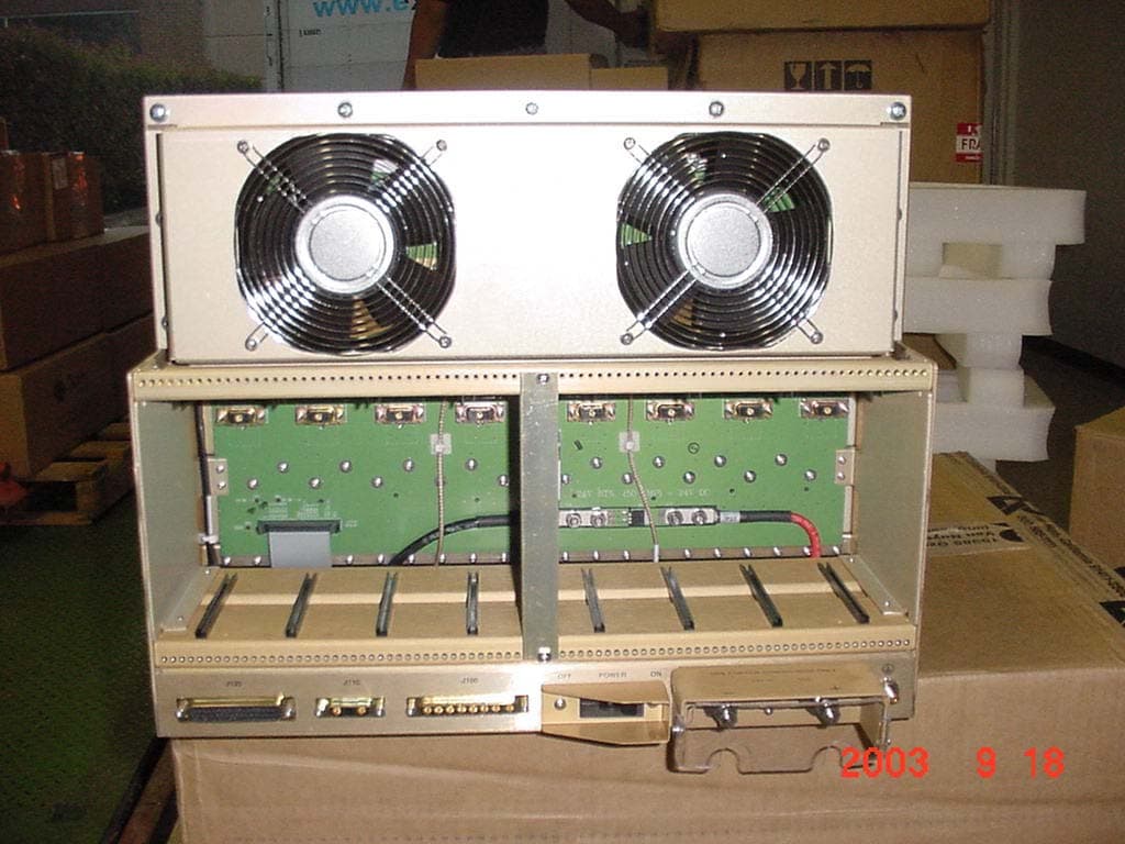
Click to zoom
Application Details
- Equipment Class
- TNB - Licensed Non-Broadcast Station Transmitter
- Date of Grant
- Sep 28, 2003
- Application Purpose
- Original Equipment
- Date of Application
- Sep 28, 2003
- Equipment Note
- Ripwave Base Station
- Frequency Range
- 2345.00000000 - 2360.00000000
- Company
- Cisco Systems, Inc
- Country
- United States
Documents & Files
Document Text
Text extracted from the exhibit documents filed with the FCC. Open a document above to read the original.
Users Manual
Ripwave ™ Base Station User Manual Part Number 40-00197-00 Revision C (1.20), Version 1.0 September 26, 2003 Proprietary All information disclosed by this document is the proprietary property of Navini Networks, Inc. and is protected by copyright, trademark, and/or trade secret laws. All rights therein are expressly reserved. Base Station User Manual Navini Networks, Inc. About This Document Purpose This manual provides an overview for the Navini Networks Base Station. Topics included are installation of the Base Transceiver Station (BTS), Radio Frequency Subsystem (RFS), and cabling; and testing and commissioning the Base Station. Revision History Date Revision / Version Author Editor Comments Sept 17, 2003 A / 1.0 P. Prudhomme S. Redfoot Release of Base Station user manual for FCC submission. Sept 18, 2003 B / 1.0 P. Prudhomme S. Redfoot Edit specifications. Sept 26, 2003 C / 1.0 P. Prudhomme S. Redfoot Add output power information Contacts Contact Navini Networks Technical Support during normal business hours: Monday through Friday 8:30 a.m. to 5:30 p.m. Central Time. You can also submit questions or comments by web or email at any time. Corporate Headquarters: (972) 852-4200 Technical Support: 1-866-RIPWAVE Web Address: www.navini.com / select Technical Support E-mail: [email protected] Navini Networks, Inc. 2240 Campbell Creek Blvd. Suite 110 Richardson, Texas 75082 USA 2 Part #40-00197-00 Rev C v1.0 (1.20) September 26, 2003 Navini Networks, Inc. Base Station User Manual Permissions, Trademarks & Distribution Copyright © September 2003, Navini Networks, Inc. All information contained herein and disclosed by this document is the proprietary property of Navini Networks, Inc. and all rights therein are expressly reserved. Acceptance of this material signifies agreement by the recipient that the information contained in this document is confidential and that it will be used solely for the purposes set forth herein. Acceptance of this material signifies agreement by the recipient that it will not be used, reproduced in whole or in part, disclosed, distributed, or conveyed to others in any manner or by any means – graphic, electronic, or mechanical, including photocopying, recording, taping, or information storage and retrieval systems – without the express written permission of Navini Networks, Inc. Navini Networks, Internet at the Speed of Thought, zero-install, unwired by Navini, the Navini Networks logo, and Ripwave are trademarks of Navini Networks, Inc. Other product and company names mentioned herein may be trademarks and/or service marks of their respective owners. Nothing herein constitutes any representation, warranty, assurance, or guaranty of any kind. Because of continuing developments and improvements in design, manufacturing, and deployment, material in this document is subject to change without notification and does not represent any commitment or obligation on the part of Navini Networks, Inc. Navini Networks, Inc. shall have no liability for any error or damages resulting from the use of this document. Any unauthorized usage is strictly prohibited without the express written permission of Navini Networks, Inc. Copyright 2003 Navini Networks, Inc. All rights reserved. Navini Networks, Inc. 2240 Campbell Creek Boulevard Suite 110 Richardson, Texas 75082 USA Part #40-00047-01 Rev C v1.0 (1.20) 3 September 26, 2003 Base Station User Manual Navini Networks, Inc. TABLE OF CONTENTS ABOUT THIS DOCUMENT.............................................................................................................2 P ERMISSIONS, TRADEMARKS & DISTRIBUTION...........................................................................3 S AFETY........................................................................................................................................5 R EGULATORY INFORMATION.......................................................................................................7 B ATTERY CAUTION & PROCEDURES............................................................................................8 GLOSSARY OF TERMS & ABBREVIATIONS...................................................................................9 OVERVIEW................................................................................................................................17 R IPWAVE DESCRIPTION..............................................................................................................17 P ROCEDURAL DOCUMENTS & FORMS........................................................................................18 H IGH-LEVEL I&C PROCESS........................................................................................................19 BASE STATION COMPONENTS...........................................................................................30 BASE TRANSCEIVER STATION (BTS).........................................................................................30 R ADIO FREQUENCY SUBSYSTEM (RFS).....................................................................................31 G LOBAL POSITIONING SYSTEM (GPS).......................................................................................32 M OUNTING RACKS & ENCLOSURES...........................................................................................33 G ENERAL SPECIFICATIONS.........................................................................................................34 B ASE STATION SPECIFICATIONS.................................................................................................35 M ATERIALS SPECIFICATIONS.....................................................................................................37 APPENDIX A: RFS IDENTIFICATION LABEL.................................................................39 2.3 GHZ RFS – OMNI HIGH BAND............................................................................................39 2.3 GH Z RFS – OMNI LOW BAND.........…
Text truncated - open the document above for the full version.
Users Manual
I&C Guide 9/26/2003 Appendix L: Antenna Power & Cable Selection Overview This section provides formulas and data that are necessary inputs for determining the right cable to be measured, cut, and installed. There are 3 types of cables that are part of the Base Station installation: antenna cables, calibration (cal) cable, and data/power cable. The antenna cables are the eight cables that carry amplified RF signals. They run between the RF/PA cards and the 8 antenna elements. The calibration (cal) cable is a single RF coaxial cable that provides an RF feedback path for calibrating the system. It runs between the backplane of the digital shelf and the RFS. The data/power cable may or may not be a separate cable from the cal cable. It is possible to use different types of cable with different loss factors for the antenna cables and cal cable. The formulas presented in this section call for either an antenna cable loss or a cal cable loss. Most applications deploy the same cable type for both the antenna and cal cables. To determine the type of cable and acceptable loss of that cable for a site, the operating transmit and receive range must be known. This is commonly referred to as the maximum transmit output power and the receiver sensitivity range. The operating transmit power and receive range should have been identified during the site survey, or they may be based on regulatory compliance. Determining the cable type and acceptable loss for a site are typically driven by two goals: (1) Which is the least expensive cable; and (2) Which has the higher (normally) loss. Whether or not the goals are achieved is determined by the output power. For example, the maximum transmit output power for a 2.6 Base Station might be given as +30dBm, or 1 Watt, to the antenna. An example of receiver sensitivity for a 2.6 system would be given as – 80 to –90 dBm. In addition to cable power loss, other types of loss have to be factored - for example, the calibration board. The calibration board is part of the RFS that samples the energy being transmitted from or received by the 8 antenna elements and combines that energy which is used when performing a calibration on the Base Station. This loss, plus cable loss and other types of loss in the equipment are called out in the following procedure. Procedure Read and follow the 7 steps/formulas below, in the order shown, to determine the resulting PA/RFS output power and desired transmit and receive calibration range for the type of Base Station you will be installing. Refer to Tables L1 and L2 to complete the steps. Table L1 provides Base Station operating parameters based on system type (2.3, 2.4, etc.), as well as other variables. Table L2 provides cable attenuation data. Before you begin, read through the steps/formulas, notes, and Table L1 in detail. Refer to the column letters at the top of Table L1 to locate the appropriate values requested in some of the formulas. Note that step/formula 1 contains a sub-procedure for determining antenna cable loss using Table L2. I&C Guide 9/26/2003 Determine the maximum capable BTS output power to the antenna. = [(PA Output to Meet FCC) or (to Meet SNR)] – BTS Loss – RFS Loss – BTS Antenna Cable Loss* [Column A or B] 1 – [Column E] 2 – [Column F or G] – [Calculated* or Measured] • BTS Antenna Cable loss < 18 dB for ACTIVE RFS configurations • BTS Antenna Cable loss < 8 dB for PASSIVE RFS configurations Change the EMS settings accordingly. *Sub-procedure: Calculate BTS antenna cable loss, referring to Table 8. = [[Distance (length in ft) 100 ft] x Attenuation value/cable type] + 0.6 for 6 connectors/3 cables .. Determine the maximum BTS output power that can be calibrated. = Max Synth Input + Cal Cable Loss + Min Cal Board Loss 3 + Backplane Loss 4 [Column K] + [Calculated or Measured] + [Note 3 ] + [Default of 5.0 in EMS or Measured] Determine the actual** max BTS output power available to the antenna. = The lesser of the two values of Step/Formula 1 and Step/Formula 2 (aka, the “floor”) ** Actual is what you can calibrate the BTS at. Determine the minimum BTS output power that can be calibrated . = Min Synth Input + Cal Cable Loss + Max Cal Board Loss 3 + Backplane Loss 4 [Column J] + [Calculated or Measured] + [Note 3 ] + [Default of 5.0 in EMS or Measured] Determine the actual ** maximum EIRP. = Step/Formula 3 + Antenna Gain. The antenna gain is affected by the type of antenna (omni, panel, 2.3, 2.4, etc.) and refers to the values in the RFS Configuration Script that accompanied the antenna from Manufacturing. **Actual is what you can calibrate the BTS at. Determine the minimum BTS RX input power that can be calibrated. = Min Synth Output - Cal Cable Loss - Min Cal Board Loss 3 - Backplane Loss 4 [Column H] - [Calculated or Measured] - [Note 3 ] - [Default of 5.0 in EMS or Measured] Determine the maximum BTS RX input power that can be calibrated. = Max Synth Output - Cal Cable Loss -Max Cal Board Loss 3 - Backplane Loss 4 [Column I] - [Calculated or Measured] - [Note 3 ] - [Default of 5.0 in EMS or Measured] Antenna Cable Selection Step/Formula 2 Step/Formula 4 Step/Formula 3 Step/Formula 5 Step/Formula 6 Step/Formula 7 Cal Cable Selection Step/Formula 1 .. I&C Guide 9/26/2003 NOTES 1 This note pertains to Step/Formula 1: For PA_Output_Power, if in the U.S. use Column A. If outside the U.S., as a precaution contact Navini Technical Support (Engineering) for sign-off. The value input cannot be more than the value shown in Column B. 2 This note pertains to Step/Formula 1: BTS_Loss is either (a) loss with a filter - i.e., if operating in the U.S. or other market that requires a filter, or (b) loss with a bypass cable. The first number (+1) is the correct value if a standard filter is used. The second number (0.4) is the correct value if a bypass cable is used. In Column D, for a 2.3 GHz system the values are the same for both the 8-carrier and the 10-carrier systems. 3 Min loss in Cal Board is 27 dB. Max loss in Cal Board…
Text truncated - open the document above for the full version.
Cover Letter(s)
American Telecommunications Certification Body Inc. 6731 Whittier Ave, McLean, VA 22101 September 24, 2003 RE: FCC ID: PL6-WCS-BTS1 Attention: John Grabner I have a few comments on this Application. 1. Please note that I cannot open the following schematic files: Confidential_62-17123-10a.pdf. Does this schematic have anything to do with the power or frequency determining capability of the rf? If so, I will need to review it. Please provide a new document. - new schematc provided 2. Please note that the manual states 20cm separation is needed. Please note that the MPE calculated for a 30dBm delivered to an 18dBi antenna as mentioned in the manual means that a minimum separation distance of 32 cm is required for general public and 71 cm is required for occupational/controlled. Please provide an MPE report showing your calculations for safe distances. Please correct the manual to use an appropriate safe distance (e.g. 1 meter). Please note that a warning statement on or near the antenna will have to be used. Please provide a copy of this label / statement. - 1. meter 3. The table and notes on page 5 of the report appear to indicate that the power delivered to the antenna port of the device will never exceed 1W (30dBm). Please verify the manner in which this is accomplished (AGC etc). - ok 4. Please note that for this frequency range of the fundamental power and spurious emissions limits are expressed in EIRP. Please provide evidence that the device meets the EIRP power limitations of 27.50. - ok 5. Please note that Spurious emissions is to be measured in the same units and method as power. Please note that for part 27 devices in this frequency range spurious emissions needs to be EIRP, not ERP. Please correct the report to reflect the proper methods and limits. - ok 6. In the test details section 9 of the report under EIRP, please reference the proper TIA 603 document (your reference is TIS630 which is a different document) - ok 7. Dennis Ward mailto:[email protected] The items indicated above must be submitted before processing can continue on the above referenced application. Failure to provide the requested information may result in application termination. Correspondence should be considered part of the permanent submission and may be viewed from the Internet after a Grant of Equipment Authorization is issued. Please do not respond to this correspondence using the email reply button. In order for your response to be processed expeditiously, you must submit your documents through the AmericanTCB.com website. Also, please note that partial responses increase processing time and should not be submitted. Any questions about the content of this correspondence should be directed to the sender.
External Photos
front of rf chassis left side of rf chassis right side rf chassis back of rf chassis front of digital chassis left side of d igital chassis right side of digital chassis 1 back of digital chassis
ID Label/Location Info
1 Navini RFS Warning Label Navini Part Number: 40-00198-00Material : Polycarbonate, .010 thick with TEDLAR lamination, adhesive backed with 3M 467 (or equivalent) adhesive. 3.00 +/-.03 32 POINT ARIAL BOLD BLACK WARNING: MAINTAIN A MINIMUM PERSONAL DISTANCE OF 1 METER FROM THIS ANTENNA DURING OPERATION ENSURE ALL RF POWER IS DISABLED BEFORE ATTEMPTING TO SERVICE OR WORK WITHIN 1 METER OF THIS DEVICE 40-00198-00 5.00 +/-.03 14 POINT ARIAL BOLD BLACK 9 POINT ARIAL BOLD BLACK YELLOW BACKGROUND
Internal Photos
back of pa baseplate back of rf chassis back of xcvr bottom of cc bottom of chp bottom of if bottom of mdm 2 bottom of syn term 2 bottom of syn channel filter front and top for 2355 channel filter top and back channel fiter top for 2310 front of empty rf chassis front of fully loaded rf chassis 2 front of pa baseplate front of xcvr pcb_top fully assemble pa_backside fully assemble pa_top pa with cover off pa without fence and cover syn bottom without shield syn shields syn top without shield 2 syn top top of cc top of chp top of if without shield top of if top of mdm top of pa psa top of syn term 2
RF Exposure Info
S= power density P= power input to the antenna G= power gain of the antenna in the direction of 1 interest relative to an isotropic radiator R= distance to the center of radiation of the antenna Choose ENTER Occupational/Controlled -(BTS) General Population/Uncontrolled -(MODEM) Tx Frequency: 2360.00 (MHz) Maximum Peak Power at Antenna Input Terminal: 38.00 (dBm) Antenna gain (typical): 18.00 (dBi) S=5.00 (mW/cm^2) P=6309.57 (mW) G=63.10 (numeric) R =79.60(cm) NOTE: The following warning must appear in the installation manual. CAUTION: This device is intended to be used with an antenna mounted to a fixed, outdoor structure. This device is a radio frequency transmitter. It is required to comply with FCC RF exposure requirements for mobile transmitting devices. A minimum separation distance of 80.00cm or more must be maintained between the antenna and all persons during device operations to ensure compliance with the FCC’s rules for Radio Frequency Exposure. If this minimum distance cannot be maintained, exposure to RF levels that exceed the FCC's limits may result. 80cm calculation is based on the maximum peak power. Max conducted RMS power to antenna port = +30 dBm Peak to Average ratio = 8 dB Antenna gain = 18 dBi OET Bulletin 65, Edition 97-01 Prediction of MPE Limit Equation from page 18 2 4R PG S π = 4 R PG S π = Maximum peak power to antenna terminal = +30 + 8 dB(p/A) = +38 dBm
Test Report
Nemko Test Report: 2L0436RUS1 Applicant: Navini Networks 2240 Campbell Creek Blvd. Suite 110 Richardson, TX 75082 Equipment Under Test: 2.3 GHz WCS Band BTS (E.U.T.) In Accordance With: FCC CFR 47, PART 27, Subpart C Wireless Communication Services Tested By: Nemko Dallas Inc. 802 N. Kealy Lewisville, Texas 75057-3136 Authorized By: John Fish, Senior EMC Engineer Date: 9/26/2003 Total Number of Pages: 86 Nemko Dallas FCC PART 27, SUBPART C WIRELESS COMMUNICATION SERVICES PROJECT NO.:2L0436RUS1 EQUIPMENT: 2.3 GHz WCS BTS Page 2 of 86 Table of Contents Section 1. Summary of Test Results............................................................................3 Section 2. General Equipment Specification...............................................................4 Section 3. RF Power Output........................................................................................6 Section 4. Occupied Bandwidth...................................................................................7 Section 5. Spurious Emissions at Antenna Terminals...............................................13 Section 6. Field Strength of Spurious........................................................................27 Section 7. Frequency Stability...................................................................................31 Section 8. Test Equipment List..................................................................................76 Section 9. Test Details...............................................................................................77 Section 10. Test Diagrams..........................................................................................83 Nemko Dallas FCC PART 27, SUBPART C WIRELESS COMMUNICATION SERVICES PROJECT NO.:2L0436RUS1 EQUIPMENT: 2.3 GHz WCS BTS Page 3 of 86 Section 1. Summary of Test Results Manufacturer: Navini Networks Model No.: 2300-Digital, 2300-RF Serial No.: None General: All measurements are traceable to national standards. These tests were conducted on a sample of the equipment for the purpose of demonstrating compliance with FCC Part 27, Subpart C. New Submission Production Unit Class II Permissive Change Pre-Production Unit THIS TEST REPORT RELATES ONLY TO THE ITEM(S) TESTED. THE FOLLOWING DEVIATIONS FROM, ADDITIONS TO, OR EXCLUSIONS FROM THE TEST SPECIFICATIONS HAVE BEEN MADE. NONE See “ Summary of Test Data”. Nemko Dallas Inc. authorizes the above named company to reproduce this report provided it is reproduced in its entirety and for use by the company’s employees only. Any use which a third party makes of this report, or any reliance on or decisions to be made based on it, are the responsibility of such third parties. Nemko Dallas Inc. accepts no responsibility for damages, if any, suffered by any third party as a result of decisions made or actions based on this report. This report applies only to the items tested. Summary Of Test Data NAME OF TEST PARA. NO. SPEC. RESULT RF Power Output 2.1046/27.50(a)(1) 2000 W EIRP Complies Occupied Bandwidth 2.1049/27.53(a) 27.53 (a) Mask Complies Spurious Emissions @ Antenna Terminals 2.1051/27.53(a) 27.53(a) Complies Field Strength of Spurious Radiation 2.1053/27.53(a) 27.53(a) Complies Frequency Stability 2.1055/27.54 27.53 (a) Mask Complies Footnotes: Nemko Dallas FCC PART 27, SUBPART C WIRELESS COMMUNICATION SERVICES PROJECT NO.:2L0436RUS1 EQUIPMENT: 2.3 GHz WCS BTS Page 4 of 86 Section 2. General Equipment Specification Supply Power: 27 Vdc Frequency Range: 2305 – 2320 MHz 2345 – 2360 MHz Type(s) of Modulation: F3E (Voice) F1D F2D D7W (QAM) DQPSK (F9W) Emission Designator: 500KD7W Output Impedance: 50 ohms RF Power Output Rated: 398 watts eirp (see page 5) +30 dBm (1 watt) at antenna terminals for all configurations. +36 dBm (4 watts) at EUT for 10 carrier configuration +37 dBm (5 watts) at EUT for 8 carrier configuration +37 dBm (5 watts) at EUT for 6 carrier configuration Duty Cycle: Software controlled 50% to 75% TDD Operator Selection Of Operating Frequency: Software controlled Power Output Adjustment Capability: Software controlled Nemko Dallas FCC PART 27, SUBPART C WIRELESS COMMUNICATION SERVICES PROJECT NO.:2L0436RUS1 EQUIPMENT: 2.3 GHz WCS BTS Page 5 of 86 Description Of EUT The EUT is a high capacity, broadband data communication Base Station Transceiver. The EUT can operate in WCS channels AB high, AB low, C, or D by design with appropriate block or channel filters inserted into the EUT. Three capacity configurations are available which consists of 10, 8, or 6 Carriers. A Carrier is a fundamental transmitter signal that is 500 kHz wide in bandwidth. An EUT Channel Bandwidth of 5 MHz consists of 10 Carriers each with a 500 kHz bandwidth. The following table summarizes the three capacity configurations for an EUT: Capacity Configurations WCS Channels Number of Carriers EUT Channel Bandwidth Max EUT Power Output * Loss to ANT Max Power to ANT Terminal** 1 A or B 10 5 MHz +36 dBm 6 dB +30 dBm 2 A or B 8 4 MHz +37 dBm 7 dB +30 dBm 3 C or D 6 3 MHz +37 dBm 7 dB +30 dBm * EUT output power will be lowered dB for dB Loss to ANT is lower. **Power to ANT terminal will be lowered dB for dB Loss to ANT is higher. EIRP is calculated as follows: Max. antenna gain = 18dBi Max BTS rf output = +30 dBm RMS Peak-to-Average Ratio = 8 dB Max. rf output power = 30 dBm + 8 dB + 18 dBi = +56 dBm (Peak EIRP) System Diagram BTS (EUT) CPE Antenna Nemko Dallas FCC PART 27, SUBPART C WIRELESS COMMUNICATION SERVICES PROJECT NO.:2L0436RUS1 EQUIPMENT: 2.3 GHz WCS BTS Page 6 of 86 Section 3. RF Power Output NAME OF TEST: RF Power Output PARA. NO.: 2.1046 TESTED BY: Tom Tidwell DATE: 9/3/2002 Test Results: Complies Measurement Data: Power Output RF Power Output Max. Antenna Gain RF Power Output (EIRP) (dBm) (Watts) (dBi) (Watts) +30 1 watt @ Antenna input 18 398 +36 4 watts @ EUT rf output with 10 carriers. 1 watt @ antenna input 18 398 +37 5 watts @ EUT rf output with 8 carriers. 1 watt @ antenna input 18 398 +37 5 watts …
Text truncated - open the document above for the full version.
Contact Information
Applicant
Gerard Thorpe(Manager , EMC Standards and Operations)
Technical Contact
Navini NetworksJohn Grabner
[email protected]214-684-7471
2240 Campbell Creek Blvd · Richardson, Texas · United States
Technical Specifications
| # | Rule Parts | Frequency Range | Power Output | Emission | Tolerance |
|---|---|---|---|---|---|
| 2 | 27 | 2.35 GHz - 2.36 GHz | 1 W | 500KD7W | 10 ppm |
Other Applications from Cisco Systems, Inc

PL6-2484-B8415-R1
Jan 27, 2010WiMAX Base Station, Broadband Wireless, 2.5/2.6 GHz
Equipment Class
TNB - Licensed Non-Broadcast Station Transmitter
PL6-2496-BTS3-R2
Mar 10, 2008BTS Transceiver
Equipment Class
TNB - Licensed Non-Broadcast Station Transmitter
PL6-2300-BTS3-R2
Mar 06, 2008BTS Transceiver
Equipment Class
TNB - Licensed Non-Broadcast Station Transmitter
PL6-2496-BTS4-R1
Mar 05, 2008BTS Transceiver
Equipment Class
TNB - Licensed Non-Broadcast Station Transmitter
PL6-2300-BTS4-R1
Mar 05, 2008BTS Transceiver
Equipment Class
TNB - Licensed Non-Broadcast Station Transmitter