PM9MURS2MURS Transceiver TX Portion
ASE Telecom Co Ltd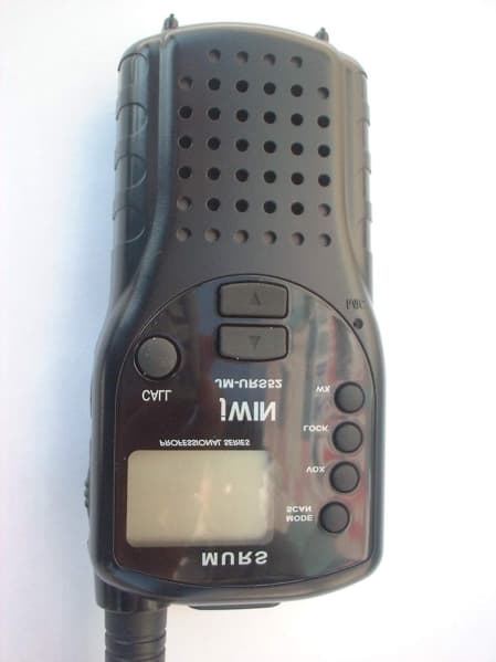
Click to zoom
Application Details
- Equipment Class
- TNF - Licensed Non-Broadcast Transmitter Held to Face
- Date of Grant
- Apr 30, 2002
- Application Purpose
- Original Equipment
- Date of Application
- Feb 28, 2002
- Equipment Note
- MURS Transceiver TX Portion
- Frequency Range
- 151.82000000 - 154.60000000
- Company
- ASE Telecom Co Ltd
- Country
- South Korea
Documents & Files
Document Text
Text extracted from the exhibit documents filed with the FCC. Open a document above to read the original.
Users Manual
7. Instruction Manual 1) General a) General This equipment, MURS is called 2 way portable handheld radios. The frequency range is 151.8200154.6000MHz, VHF operating channels for International 2 way portable radios. b) Characteristic a. All active device in this radio is composed of semiconductor and high density IC. b. To design this radio in compact and weight approximately 140g including battery. c. CPU of this equipment is HD4048912 from HITACHI. d. It's power can operate by use of alcaline 4 cell(1.5V AA) battery. c) Composition This radio is composed of following. a. Transmitter(W/Antenna) b. Belt clip c. Ni-MH battery(option) 2) Specification a) General Specification a. Frequency Range : 151.8200154.6000MHz b. Output Impedance : 50Unbalanced c. Modulation Type : 8K0F3E d. Communication Mode : Half duplex e. Channel Capacity : 5 channel f. Channel spacing : 12.5 KHz g. Power : 6.0V(alkaline) h. Battery Life : ALCA.1100mAh >40 hours (Tx5%, Rx5%, Stand-by 90%) i. Operating Temperature : -30+60 j. Dimension : 95.5(H)x 50(W)x 26(D)mm k. Weight : 140g(with Battery) b) Electrical Specification a. Transmitter 1. Output power : Max. 2.0W 2. Frequency Stability : 5.0 ppm(-30+60) 3. Modulation Method : FM 4. Oscillation Method : PLL SYNTHESIZER 5. Max. Frequency Deviation : < 2.5 KHz (with tone) 6. Cooling Method : air-cooling Method 7. Spurious Emission : < -53dBc 8. FM Hum/Noise : > -40dB(1kHz 60% modulation,w/CCITT) 9. Distortion : < 5% (1kHz 60% modulation) 10. Tx Audio Response : 6dB /OCT 3dB PRE-EMPHASIS(300Hz2.5kHz) b. Receiver 1. Receive Method : Double Super Heterodyne 2. Receive Sensitivity : 0.282uV from 0.158uV 3. Squelch Sensitivity : Auto 0.282uV from 0.158uV 4. Bandwidth : > 3kHz(6dB ATT point) 5. Selectivity : < -60dB(12.5kHz) 6. Local Frequency Stability : 5ppm(-30+60) 7. Spurious Rejection : > 50dB 8. Image Rejection : > 40dB 9. Intermodulation : > 40dB 8. Audio output : Max 300mW(Internal 8 load THD 10%) Ext.100mW 9. Distortion : < 5% (1kHz 60% Modulation) 10. RX Audio Response : 6dB/OCT 3dB DE-EMPHASIS(300Hz2.5kHz) 11. S/N Ratio : < 40dB(1kHz 60% modulation w/CCITT) 12. IF : 1'st IF = 21.7MHz 2'nd IF = 450kHz 13. Local Frequency : 1st Local Frequency = fc - 21.7MHz 2nd Local Frequency = 21.25MHz 3) Operation a) Key Name 1. Antenna 2. Belt clip 3. Power (Red button) 4. Speaker/Microphone/Charger jack 5. Mode/Scan 6. VOX (Voice Activated Operation) 7. Lock 8. WX (Weather Broadcast Channels) 9. Scroll key 10. Microphone 11. Battery cover 12. Charging pads 13. Battery cover latch 14. Backlit LCD 15. Push-to-talk 16. Monitor/Lamp 17. Call 18. Speaker b) Turn The Radio On/Off 1. Press the power button(Red). You will hear a confirming melody to Indicate the unit is on and the LCD displays ready saved channel settings. 2. To turn the unit off, press and hold the power button(Red) for at least 2 seconds. You will hear a confirming melody to indicate the unit is off. c) Adjust Volume 1. With the unit powered on, press the Up button () to increase volume and the down button () to decrease volume. 2. The volume level has 8 steps, and the display will indicate the current volume level by the 0 from 7 to. d) Transmitting a Call Tone 1. You can alert another party that you wish to communicate. 2. Press and release Call button, well then the LCD will display CALL, then the unit you are calling will hear a two second ringing tone. 3. This MURS2 radio has 5 different Call Tones. Please refer to Menu chapter to set different Call Tone. e) Receiving a Call 1. The radio is continuously in receiving mode when powered on. 2. Incoming signal can be heard only when both (transmitter & receiver) radio are on the same channel & CTCSS. 3. RSSI bar icon appears when a signal is being received. The icon consists of five bars to indicate the received signal level. f) Transmitting a Call 1. Press and hold the push-to-talk button, and speak gently into the microphone about 3 inches away from the radio. 2. The LCD will display this icon when press and hold the PTT (Push-To-Talk) button. 3. Release the PTT button when finished transmission. g) Monitor/Display Backlight Button This feature turns off the Automatic Squelch feature momentarily. This allows your unit to receive all signals to its maximum range, but it may pick up static signals as well. You can set the speaker volume by the noise of the static. Do not transmit if you hear conversation. To activate this, press the Monitor button for up to 0.5 seconds. To restore the automatic squelch, release the Monitor button. By pressing the momentarily, the LCD backlight is turned on; the LCD backlight will turn off automatically in about 5 seconds, or when the monitor button is pressed momentarily once again. h) Mode/Scan This feature allows you to monitor all channels automatically for valid signals. While scanning, you can transmit and receive. When a signal is received, the scan is interrupted and will return to scan mode 5 seconds after reception is terminated. 1. Press and hold MODE/SCAN button, SCAN icon will appear on the LCD display. 2. The radio will display each channel (1-5) in order as the scan mode operates to find an active main channel. 3. When unit doesn’t find any signals and you want to transmit, press the PTT switch to return to home channel operation. The transceiver will automatically resume scanning approximately 5 seconds after the communication is completed. 4. If there is no activity and you want to leave the scan mode, press the PTT button and the unit will return to normal operation. SCAN icon will disappear from the LCD display. i) VOX Mode This feature enables you to have hand-free conversation. Your voice or nearby sound is detected and the radio transmits without the need to press the PTT button. To set radio for VOX operation, From MURS2 standby mode, press the VOX button, VOX icon will appear on the LCD display. j) Set The Channel In order to communicate with other MURS2 units, both transmitting and receiving party must to th…
Text truncated - open the document above for the full version.
Cover Letter(s)
Timco Engineering Inc. 849 NW State Road 45 Newberry FL 32669 Page 1 of 1 From: Mario de Aranzeta [email protected] To: Andy Leimer [email protected] FCC Application Processing Branch Re: FCC ID PM9MURS2 Applicant: ASE Telecom Co. Ltd. Correspondence Reference Number: 22598 731 Confirmation Number: EA296165 1) The specifications and tune-up procedure say that the conducted power is 2 W (high) and 0.5 W (low). The measures ERP is 0.35 W (high) and 0.02 W (low). I would not expect the ERP to be that much lower than the conducted power. Please explain. Two things account for the low ERP output. The antenna is a helically wo und wire with low gain. The seco nd is that the unit is tuned up on the bench using a power supply and when run o ut o n the OATS the unit is powered by 4 new AA batteries. Batteries and the battery holder clips have a higher internal resistance with a 0.5 Ampere drawn through them. Regards, Mario de Aranzeta Engineer
Operational Description
5) Specification sheet Receiver(FM) TRANSMITTER(FM) WX Channel(FM)
Operational Description
9. Circuit Description 1) Frequency synthesizer Frequency synthesizer consists of VCO, PLL IC(built in Prescaler) and loop filter. a) VCO VCO is composed of one VCO. Oscillation circuit takes colpitts circuit using variable Diode. And VCO is composed of D202,Q202,C203,205,206,207,L202. VCO control voltage through loop filter adjusts frequency and Microphone signal through Modulation terminal makes modulation. b) PLL IC PLL IC is adjustable IC to produce the wished frequency which VCO provides through loop filter. It has internal counter using 21.25MHz reference frequency to make 6.25kHz as reference Signal. VCO frequency from prescaled input is divided signal is compared with Reference signal phase in phase comparator. Built-in charger pump changes voltage (until two signals are in phase) and charged voltage supplies VCO through loop filter to produce the desired frequency. Frequency data associated with channel goes to PLL IC by CPU through CLOCK, DATA. PLL IC enables by strobe line of CPU. c) Loop Filter Loop filter is composed of R221,220,C240,238,237 and changes pulse from Pin14 to DC., and eliminates harmonic component in pulse. It helps VCO oscillate clearly as DC voltage is supplied into Varicap. 2) Receiver This is composed of Dual Conversion Super Heterodyne. First IF is 21.7MHz. Local oscillator frequency is lower in 1'st IF than Rx frequency. It is called low side injection. Second IF is 450kHz. 2nd local oscillator frequency comes to 21.25MHz. a) Rx/Tx Conversion Circuit Rx signal goes to Rx/Tx conversion circuit through FIXED antenna connector, low pass filter(L310,311,312,C320,322,323,327,328) and receiver resonance circuit composed of L313,C101. When transmitting, voltage through R311,L308 D303,304 supplies,D303,304 of receive input is short and Tx is on condition. When PIN diode is off in condition of Rx, L313 and C101 resonate serially and make impedance matching at receiver band-pass filter. (CF101). b) Front End Front-End has Q101 to provide a high sensitivity and low noise feature. It employs Saw filter as band pass filter to eliminate image frequency and to produce enough pass band by Q101 input and output. c) Mixer Mixer has one base BFQ67W(Q102) to feature high low noise quality. It has RF signal through L207, CF101 and Q101 RF signal from Local oscillator mixed. It develops 1'st IF ,21.7MHz. 1st IF goes to 1st IF amplifier Q3(KTC4080) base through X-tal filter CF102. IF of mixing signals is selected and taken into X-tal filter. Output impedance of mixer is direct matched with input impedance of X-tal filter. Matching of filter satisfies pass bandwidth of filter, ripple elimination with in pass band, and attenuation characteristic of stop band. X-tal filter is composed of two pole monolithic X-tal filter, 8 kHz of IF bandwidth R113 is used as impedance matching with 1'st IF Amp Q3. d) IF AMP and Detection 1'st IF AMP Q103 supplies IF(IC101) mixer input pin16 through output resistor R122 and C128 to need gain in insertion loss of X-tal filter and last stage circuit. Multi-use IF IC makes up of mixer IF AMP. pin1 2'nd local frequency enter to pin1. It supplies mixer of internal IC. Mixer output of IC through pin3 passes 450kHz ceramic filter, supplies 2'nd IF amplifier and limits. After 2'nd IF AMP has a process of enough gain and AM rejection, it comes to quadrature detection. Demodulated audio signal by L108 (Quad Coil) is amplified and comes out to pin9. Detected audio signal through R140,IC102A/B and input in audio amp. IC103 through C151. e) Squelch Circuit Noise component of detected outputs has amplification Squelch threshold is controlled by Resistor R123,R125 f) Audio Amplifier Demodulated audio signal enters to pin2 of IC103. After above signal amplies in IC103 pin5 through C156. It comes out to pin5 Then, It reaches at speaker. 3) Transmitter When Tx develops with pressing PTT switch, VCO output amplifies through Q302,303 transmits by antenna through low pass filter. Tx RF signal produced from Tx VCO is amplified by Driver Q302 through C306 and entered Q303 Power TR input terminal with final amplification. After this stage, the signal is emitted at antenna through 50matching circuit to low pass filter(L310,311,312,C320,322,323,327,328)to eliminate harmonic. a) Audio Modulation and Audio Amplification Audio signal produced by external or internal microphone, limits amplification by IC503.. It enters to VCO through low pass filter and IC503B. Max. Frequency modulation deviation is adjusted by RV201 keeps noise and audio from entering to VCO at time of Tx. Audio modulation and Audio Amplification has characteristic of 6dB/OCT pre-emphasis by IC503D(KIA324).
Parts List/Tune Up Info
5) Adjustment a) Frequency synthesizer (PLL) a. After connecting the power meter and dumy load(50), join the antenna connector of MURS with above equipment. b. Check the voltage between TP1 & GND in digital volt meter. c. Then set the low channel of MURS the lowest frequency. d. After pressed PTT key of MURS, Air coil L202 for adjusting the lowest frequency of Tx channel to DC 1.5V in the voltage of TP1. e. After releasing the PTT key, And then check if the highest frequency of Rx channel is range DC 1.0~2.0V in the voltage of TP, b) Transmitter a. Connect EUT & measure equipment according to block diagram below. POWER SUPPLY EUT AF OSCILLATOR POWER METER DUMMY LOAD AV VTVM MODULATION METER OSCILLOSCOPE DISTORTION METER SPECTRUM ANALYZER FREQUENCY COUNTER c. The Confirm of Rx sensitivity 1. Adjust SSG to channel frequency. 2. Adjust modulation frequency, 1KHz to modulation degree, 1.5 KHz. 3. After adjusting the frequency of SSG to channel frequency, RF level sets to -47dBm. d. The Conform of Squelch sensitivity 1. Set the standard channel. 2. In squelch mode, SQ volume RV101 must be turned counterclockwise. 3. After adjusting SSG to channel frequency, the RF level of SSG is set on SINAD 86dB. e) Receiver Test a. Rx sensitivity test SSG should be adjusted to 12dB of SINAD's point needle seeing wave of oscilloscope as SSG sets in 1kHz with 1.5 KHz frequency deviation. At this time, normal RF level is -118dBm. b. Audio Distortion Test 1. SSG should be adjusted like way of point a) and RF level sets to -47dBm. 2. Adjust to 0.8Vrms(8 load) seeing Audio wave. 3. Read the needle of distortion meter(normal condition would be less than 5% distortion.) c. Squelch Test After RF level of SSG should be set to the least level, RF level should be gradually increased until speaker makes audio sound. At this point, check RF level(Check if the SINAD is 86dB) SSG EUT POWER SUPPLY 8 LOAD OSCILLOSCOPE AV VTVM DISTORTION METER SINAD METER f) Symtoms, Check point & Correction a. Diagnosis method 1. Check each switch to work well. 2. Check voltage of battery. 3. Problem develops from transmitter or receiver? b. Troubleshooting 1. Transmitter Power key is on condition but does not work. Battery could completely discharge. Battery cell twist.. Touch problem come between Battery and Radio. Fail to transmit Run out of battery or charge problem. Fault of PTT key. Fault of Q301,302,303. Transmitter works but frequency is unmatched Out of order in frequency synthesizer. Out of order in X-tal(X201). Audio does not sound(Tx power and Tx frequency are normal) Problem of microphone or mic connector. IC503 problem. Tx is set when switch is on. Tx switch problem 2. Receiver Rx does not work Speaker line open problem or connector problem. Receiver power circuit problem. Audio amplifier Base band IC103 problem. Only noise sound IC101 problem. VCO problem. Rx sensitivity is weak Antenna mounting problem. Front-End circuit problem. Local oscillation frequency deviation. SF1 saw filter fail. VCO problem. Squelch does not work IC101 problem. Control logic problem.
Test Report
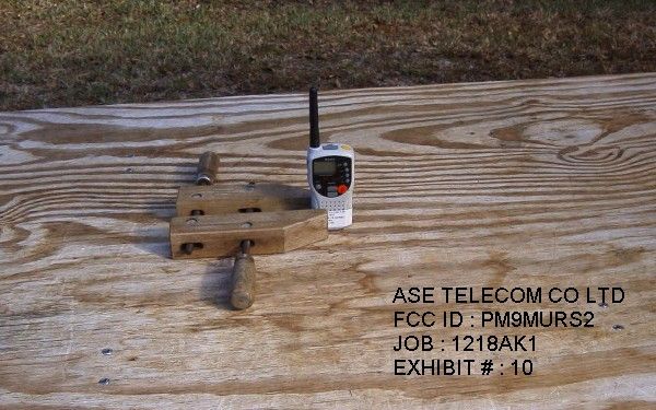
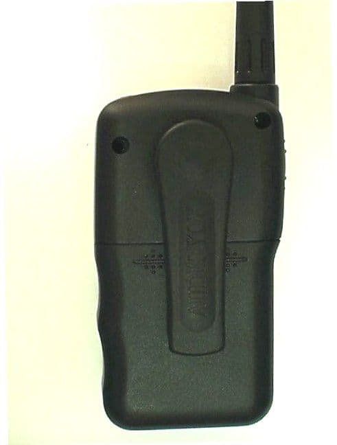
APPLICANT: ASE TELECOM CO., LTD. FCC ID: PM9MURS2 REPORT #: T:\A\ASE\1218ak1\1218ak1TestReport.doc TABLE OF CONTENTS LIST TABLE OF CONTENTS LIST APPLICANT: ASE TELECOM CO., LTD. FCC ID: PM9MURS2 TEST REPORT: PAGE 1......COVER SHEET - GENERAL INFORMATION & TECHNICAL DESCR. PAGE 2......TECHNICAL DESCRIPTION CONTINUED PAGE 3......RF POWER OUTPUT Page 4......MODULATION CHARACTERISTICS PAGE 5......AUDIO FREQUENCE RESPONSE PLOT PAGE 6......MODULATION LIMITING – 300 Hz PAGE 7......MODULATION LIMITING – 1000 Hz PAGE 8......MODULATION LIMITING - 3000 Hz PAGE 9......AUDIO LOW PASS FILTER GRAPH PAGE 10.....EMISSION BANDWIDTH PAGE 11.....OCCUPIED BANDWIDTH PLOT PAGE 12.....OCCUPIED BANDWIDTH PLOT - CW PAGE 13.....METHOD OF MEASURING OCCUPIED BANDWIDTH PAGE 14.....FIELD STRENGTH OF SPURIOUS EMISSIONS PAGE 15.....METHOD OF MEASURING RADIATED SPURIOUS EMISSIONS PAGE 16.....FREQUENCY STABILITY PAGE 17.....LIST OF TEST EQUIPMENT EXHIBITS CONTAINING: EXHIBIT 1.........FCC ID LABEL SAMPLE EXHIBIT 2.........SKETCH OF FCC ID LABEL LOCATION EXHIBIT 3.........BLOCK DIAGRAM EXHIBIT 4.........SCHEMATICS EXHIBIT 5.........USER'S MANUAL EXHIBIT 6A........EXTERNAL PHOTO - FRONT VIEW EXHIBIT 6B........EXTERNAL PHOTO – REAR VIEW EXHIBIT 6C........EXTERNAL PHOTO – SIDE VIEW EXHIBIT 6D........EXTERNAL PHOTO - TOP VIEW EXHIBIT 6E........INTERNAL PHOTO - COMPONENT SIDE EXHIBIT 6F........INTERNAL PHOTO - SOLDER SIDE EXHIBIT 7.........SPECIFICATION SHEET EXHIBIT 8.........TUNING PROCEDURE EXHIBIT 9.........CIRCUIT DESCRIPTION EXHIBIT 10........TEST SET UP PHOTO APPLICANT: ASE TELECOM CO., LTD. FCC ID: PM9MURS2 REPORT #: T:\A\ASE\1218ak1\1218ak1TestReport.doc Page 1 of 17 GENERAL_INFORMATION_REQUIRED FOR_TYPE_ACCEPTANCE 2.1033(c)(1)(2)ASE TELECOM CO., LTD..will manufacture the FCC ID: PM9MURS2 MULTI USER RADIO SERVICE TRANSCEIVER in quantity, for use under FCC RULES PART 95. The UUT is a PTT Radio with a maximum duty cycle of 50%. ASE TELECOM CO., LTD. 7F., YUNGCHANG B/D., 250 CHEOLSAN-DONG KWANGMYONG-CITY KYUNGGI-DO KOREA 2.1033 (c) TECHNICAL_DESCRIPTION 2.1033(c)(3) Instruction book. A draft copy of the instruction manual is included as EXHIBIT 5. 2.1033(c) (4) Type of Emission: 9K6F3E 95.632 Bn = 2M + 2DK M = 3000 D = 2.0K Bn = 2(3.0)+2(2.1) = 9.6K Authorized Bandwidth – 11.25 kHz for frequencies: 151.820, 151.880, 151.940 MHz Authorized Bandwidth - 12.5 kHz for frequencies: 154.570, 154.600 MHz 2.1033(c)(5) Frequency Range: 1. 151.820 95.632 2. 151.880 3. 151.940 4. 154.570 5. 154.600 2.1033(c)(6)(7) Power Output shall not exceed 2.0 Watts effective 95.639 radiated power. There can be no provisions for 95.649 increasing the power or varing the power. The antenna is an intergral part to the unit, it cannot be removed without rendering the unit inoperative. In order to remove the antenna the case must unscrewed, then the PCB assemblies must be removed then the antenna can be removed. APPLICANT: ASE TELECOM CO., LTD. FCC ID: PM9MURS2 REPORT #: T:\A\ASE\1218ak1\1218ak1TestReport.doc Page 2 of 17 2.1033(c)(9) Tune-up procedure. The tune-up procedure is shown as EXHIBIT 8. 2.1033(c)(8) DC Voltages and Current into Final Amplifier: FINAL AMPLIFIER ONLY High - Vce = 6.0 Volts DC Ice = 0.5A Pin = 3 Watts Low - Vce = 6.0 Volts DC Ice = 0.13A Pin = 0.78 Watts 2.1033(c)(10) Complete Circuit Diagrams: The circuit diagram is included as EXHIBIT 4. The block diagram is included as EXHIBIT 3 of this report. 2.1033(c)(11) A photograph or a drawing of the equipment identification label is included as exhibit No. 1. 2.1033(c)(12) Photographs(8"X10") of the equipment of sufficient clarity to reveal equipment construction and layout, including meters, labels for controls, including any view under shields - See EXHIBIT 6A-6F. 2.1033(c)(13) Digital modulation is not used in this device. 2.1033(c)(14) The data required by 2.1046 through 2.1057 is submitted below. APPLICANT: ASE TELECOM CO., LTD. FCC ID: PM9MURS2 REPORT #: T:\A\ASE\1218ak1\1218ak1TestReport.doc Page 3 of 17 2.1046(a) RF_power_output. 95.639(g) RF power is measured by measuring the radiated power at 3 meters and then replacing the transmitter with a signal generator to determine the effective radiated power. The ERP shall not exceed 2.0 Watts. MEASURED POWER OUTPUT = .35 Watts ERP HIGH POWER .02 Watts ERP LOW POWER R.F. POWER OUTPUT HP TEST SET UP Spectrum Analyzer TRANSMITTER UNDER TEST WITH INTERNAL ANTENNA <-- 3.0 meters---> SIGNAL DIPOLE Tuned, Calibrated GENERATOR ANTENNA Antenna which may be raised from 1 to 4 meters above ground and changed in polarization Equipment placed 80cm above ground on a rotatable platform. APPLICANT: ASE TELECOM CO., LTD. FCC ID: PM9MURS2 REPORT #: T:\A\ASE\1218ak1\1218ak1TestReport.doc Page 4 of 17 2.1047(a)(b) Modulation_characteristics: AUDIO_FREQUENCY_RESPONSE The audio frequency response was measured in ac- cordance with TIA/EIA Specification 603. The audio frequency response curve is shown below. The audio signal was fed into a dummy microphone circuit and into the microphone connector. The input required to produce 30 percent modulation level was measured. 2.1047(b) Audio input versus modulation The audio input level needed for a particular per- percentage of modulation was measured in accor- dance with TIA/EIA Specification 603. The audio input curves versus modulation are shown below. Curves are provided for audio input frequencies of 300, 1000, and 3000 Hz. APPLICANT: ASE TELECOM CO., LTD. FCC ID: PM9MURS2 REPORT #: T:\A\ASE\1218ak1\1218ak1TestReport.doc Page 5 of 17 ASE Telecom Co. LTD. MURS2 -55 -50 -45 -40 -35 -30 -25 -20 -15 100100010000 Frequency dBmV audio response APPLICANT: ASE TELECOM CO., LTD. FCC ID: PM9MURS2 REPORT #: T:\A\ASE\1218ak1\1218ak1TestReport.doc Page 6 of 17 Modulation Limiting ASE Telecom Co. LTD. MURS2 0 500 1000 1500 2000 2500 -42-32-22-12 dBmV Deviation 300 Hz APPLICANT: ASE TELECOM CO., LTD. FCC ID: PM9MURS2 REPORT #: T:\A\ASE\1218ak1\1218ak1TestReport.doc Page 7 of 17 Modulation Limiting ASE Telecom Co. LTD.…
Text truncated - open the document above for the full version.
Contact Information
Applicant
J H Kim(Manager)
Technical Contact
Timco Engineering, Inc.Mario R de Aranzeta
[email protected]888-472-2424
P.O. Box 370 · Newberry, Florida · United States
Non-Technical Contact
Timco Engineering, Inc.Sharon A Hoffman
[email protected]888-472-2424
Test Firm
Timco Engineering, Inc.S Sanders
Technical Specifications
| # | Rule Parts | Frequency Range | Power Output | Emission | Tolerance |
|---|---|---|---|---|---|
| 2 | 95J | 151.82 MHz - 154.6 MHz | 20.00 mW | 9K60F3E | 5 ppm |
Other Applications from ASE Telecom Co Ltd
PM9GMRS1600
Aug 01, 2002FRS/GMRS Combination Transceiver
Equipment Class
FRF - Part 95 Family Radio Face Held Transmitter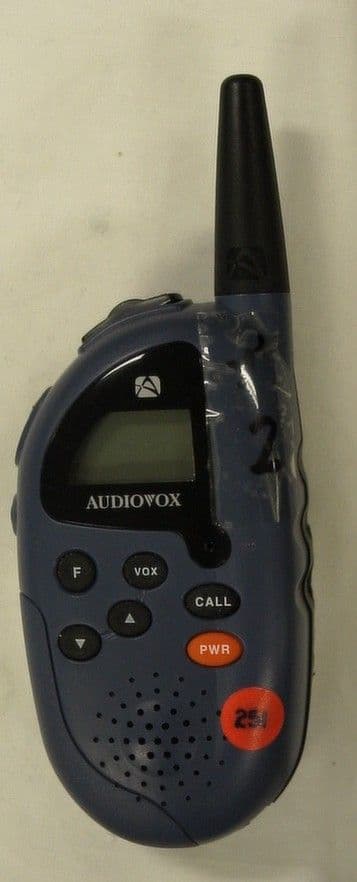
PM9FR548
Jul 11, 2002FRS
Equipment Class
FRF - Part 95 Family Radio Face Held Transmitter
PM9-GMRS1
Jul 25, 2001GMRS TRANSCEIVER
Equipment Class
TNF - Licensed Non-Broadcast Transmitter Held to Face