PMF-IS-TR-241IS-TR-241
DTE Automation GmbH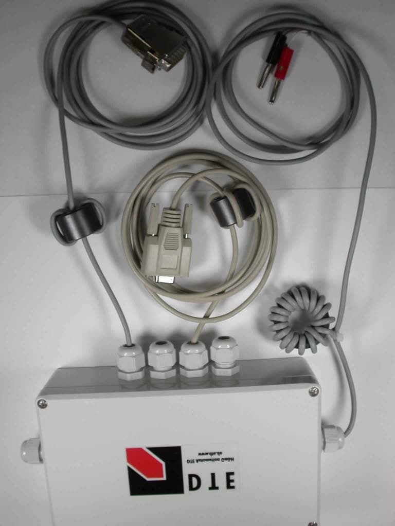
Click to zoom
Application Details
- Equipment Class
- DCD - Part 15 Low Power Transmitter Below 1705 kHz
- Date of Grant
- Dec 15, 2002
- Application Purpose
- Original Equipment
- Date of Application
- Dec 15, 2002
- Equipment Note
- IS-TR-241
- Frequency Range
- 0.13420000 - 0.13420000
- Company
- DTE Automation GmbH
- Country
- Germany
Documents & Files
Document Text
Text extracted from the exhibit documents filed with the FCC. Open a document above to read the original.
Users Manual
DTE Automation GmbH DTE Automation GmbH http://www.dte.de Phone: +49-5221-1012200 Heidestr. 38 Fax: +49-5221-1012201 32051 Herford [email protected] Germany IS-TR-241 User Manual Version 2.2 DTE Automation GmbH Version 2.2 Page 2 Table of Contents I Introduction.............................................................................................................................3 II Function................................................................................................................................4 III Reader Configuration..............................................................................................................5 IV Configuration Bytes...............................................................................................................6 CFG0...........................................................................................................................6 CFG1...........................................................................................................................8 CFG2...........................................................................................................................8 CFG3...........................................................................................................................8 CFG4...........................................................................................................................9 CFG5...........................................................................................................................9 CFG6...........................................................................................................................9 CFG7...........................................................................................................................9 V Protocol................................................................................................................................10 VI Protocol Syntax....................................................................................................................11 VII Commands Overview............................................................................................................12 VIII Technical Data....................................................................................................................15 Dimension / Weight.......................................................................................................15 Hardware......................................................................................................................15 Connector assignment...................................................................................................16 DTE Automation GmbH Version 2.2 Page 3 Introduction I Introduction This manual covers the function and the configuration information of the IS-TR-241 reader. FCC Note FCC ID: PMF-IS-TR-241 This device complies with Part 15 of the FCC rules. Operation is subject to the following two conditions: 1. This device may not cause harmful interference, and, 2. This device must accept any interference received including interference that may cause undesired operation. NOTE: "Changes or modifications not expressly approved by the party responsible for compliance could void the user’s authority to operate the equipment." "We, DTE Automation GmbH, Heidestr. 38, 32051 Herford, Germany, declare that the IS-TR-241 will be marketed with the ferrites: - DC power cable with ferrite 18 coils, Ferrite type 7427015 (Würth Elektronik) - RS232 cable with ferrite 5 coils, Ferrite type 7427014 (Würth Elektronik) - Control cable with ferrite 5 coils, Ferrite type 7427014 (Würth Elektronik) fitted to the supplied cables as indicated in the test report for this product. The product must be fitted at installation to ensure compliance with the CFR 47, Part 15, Subpart C for FCC ID: PMF-IS-TR-241. Please note that the unit does not comply with Part 15, Subpart C without these ferrites installed as indicated." Warnings Under no circumstances try to open the IS-TR-241. Electrical safety cannot be guaranteed if the device is opened by a non-expert. Your health and life are endangered due to high voltage in the electronics. In case of damage do not continue to use the devices. Send back the device to your local distributor or - along with a copy of the invoice - to DTE Automation GmbH in Herford, Germany for service support. Do not dip the device into water. Since it is only protected against water splash and rain, serious damages may occur when using or storing this device under water. Only use original cables and spare parts with this device. Copyright Copyright © 2002 by DTE Automation GmbH. All rights reserved. This manual is copyrighted works of DTE Automation GmbH. IBM PC is registered trademark of International Business Machines Corp. TIRIS is a trademark of Texas Instruments Inc. DTE GmbH acknowledges that some other names referred to are registered trademarks. DTE Automation GmbH Version 2.2 Page 4 Function II Function Basically, the reader works in a continuous read mode. In this mode the green LED is always on. At power up or after restart (use the restart button) the reader can read a configuration transponder to get new settings. After reading the new configuration, the reader goes into normal operation mode. Whenever a transponder appears, the reader reads its level and wedge information out of the transponder. If the level and wedge number is the same as stored in its configuration block the drop (relay 1) will be switched on and the red LED turns on, otherwise the no drop (relay 2) will be switched on and the yellow LED turns on. IMPORTANT: The antenna is integrated in the center of the upper shell of the housing. The best read range is achieved, when the glass transponder points to antenna. DTE Automation GmbH Version 2.2 Page 5 Reader Configuration III Reader Configuration At power up or after reset the reade…
Text truncated - open the document above for the full version.
External Photos
Attachment E1 IS-TR-241 FCC ID: PMF-IS-TR-241 File No. T 22158-01 AA MIKES BABT PRODUCT SERVICE GmbH Ohmstrasse 2-4 D-94342 Strasskirchen Tel.:+49 94 24 94 07-0 Fax:+49 94 24 94 07-60 Rev.Nr. 9.0 Attachment E2 IS-TR-241 FCC ID: PMF-IS-TR-241 File No. T 22158-01 AA MIKES BABT PRODUCT SERVICE GmbH Ohmstrasse 2-4 D-94342 Strasskirchen Tel.:+49 94 24 94 07-0 Fax:+49 94 24 94 07-60 Rev.Nr. 9.0
ID Label/Location Info
DTE Automation GmbH DTE Automation GmbH Phone: +49-5221-1012200 Heidestr. 38 Fax: +49-5221-1012201 32051 Herford · Germany [email protected] IS-TR-421 Photo of LABEL
Internal Photos
Attachment E4 IS-TR-241 FCC ID: PMF-IS-TR-241 File No. T 22158-01 AA MIKES BABT PRODUCT SERVICE GmbH Ohmstrasse 2-4 D-94342 Strasskirchen Tel.:+49 94 24 94 07-0 Fax:+49 94 24 94 07-60 Rev.Nr. 9.0 Attachment E5 IS-TR-241 FCC ID: PMF-IS-TR-241 File No. T 22158-01 AA MIKES BABT PRODUCT SERVICE GmbH Ohmstrasse 2-4 D-94342 Strasskirchen Tel.:+49 94 24 94 07-0 Fax:+49 94 24 94 07-60 Rev.Nr. 9.0 Attachment E6 IS-TR-241 FCC ID: PMF-IS-TR-241 File No. T 22158-01 AA MIKES BABT PRODUCT SERVICE GmbH Ohmstrasse 2-4 D-94342 Strasskirchen Tel.:+49 94 24 94 07-0 Fax:+49 94 24 94 07-60 Rev.Nr. 9.0 Attachment E7 IS-TR-241 FCC ID: PMF-IS-TR-241 File No. T 22158-01 AA MIKES BABT PRODUCT SERVICE GmbH Ohmstrasse 2-4 D-94342 Strasskirchen Tel.:+49 94 24 94 07-0 Fax:+49 94 24 94 07-60 Rev.Nr. 9.0 Attachment E8 IS-TR-241 FCC ID: PMF-IS-TR-241 File No. T 22158-01 AA MIKES BABT PRODUCT SERVICE GmbH Ohmstrasse 2-4 D-94342 Strasskirchen Tel.:+49 94 24 94 07-0 Fax:+49 94 24 94 07-60 Rev.Nr. 9.0 Attachment E9 IS-TR-241 FCC ID: PMF-IS-TR-241 File No. T 22158-01 AA MIKES BABT PRODUCT SERVICE GmbH Ohmstrasse 2-4 D-94342 Strasskirchen Tel.:+49 94 24 94 07-0 Fax:+49 94 24 94 07-60 Rev.Nr. 9.0
Operational Description
DTE Automation GmbH DTE Automation GmbH http://www.dte.de Phone: +49-5221-1012200 Heidestr. 38 Fax: +49-5221-1012201 32051 Herford · Germany [email protected] © 2001 Copyright by DTE Automation GmbH Operating Description IS-TR-241 TIRIS Version page 2 of 2 Operating Description Basically, the reader works in a continuous read mode. In this mode the green LED is always on. At power up or after restart (use the restart button) the reader can read a configuration transponder to get new settings. With this special transponder you can set an operating mode for the reader and values for full trigger time or read trigger time, lane free trigger time or read error time, relay 1/2 delay time, relay 1/2 on time, level number and wedge number. After reading the new configuration, the reader stores the configuration permanent in his non volatile memory and goes into normal operation mode. Whenever a transponder appears, the reader reads its level and wedge information out of the transponder. If the level and wedge number is the same as stored in its configuration block the drop (relay 1) will be switched on and the red LED turns on, otherwise the no drop (relay 2) will be switched on and the yellow LED turns on. If the lane full sensor is enabled and the input is active the reader will always activate the no drop (relay 2) until the input is inactive for lane free trigger time again. IMPORTANT: The antenna is integrated in the center of the upper shell of the housing. The best read range is achieved, when the glass transponder points to antenna.
Test Report
FCC ID: PMF-IS-TR-241 TTI - P-G 009 / 98-00 TTI - P-G 089 / 94-50 File No. 1 of 16 MIKES BABT PRODUCT SERVICE GmbH Ohmstrasse 2-4 94342 Strasskirchen Tel.:+9424-9407-0 Fax:+9424-9407-60 Rev. No. 9.0 T 22158-1-01 AA , Page E M I S S I O N -- T E S T R E P O R T Test Report File No. : T 22158-1-01 AA ________________ Date : November 25, 2002 of issue ________________ Type Designation : IS-TR-241 ______________________________________________ Kind of Product : Radio Frequency Identification ______________________________________________ Applicant : DTE Automation GmbH ______________________________________________ Manufacturer : DTE Automation GmbH ______________________________________________ Licence holder : DTE Automation GmbH ______________________________________________ Address : Heidestrasse 38 ______________________________________________ 32051 Herford, Germany ______________________________________________ Test result accdg. to the regulation(s) at page 3 : Positive This test report with attachment consists of 32 pages. The test result only corresponds to the tested sample. It is not permitted to copy this report, in part or in full, without the permission of the test laboratory. FCC ID: PMF-IS-TR-241 File No. 2 of 16 MIKES BABT PRODUCT SERVICE GmbH Ohmstrasse 2-4 94342 Strasskirchen Tel.:+9424-9407-0 Fax:+9424-9407-60 Rev. No. 9.0 T 22158-1-01 AA , Page D I R E C T O R Y Page Documentation Directory 2 ________ Test regulations 3 ________ General information 4-5 ________ Discovery of worst case condition 6 ________ Equipment under Test 15 ________ Summary 16 ________ Test data Conducted emissions 10/150 kHz - 30 MHz 7 ________ Spurious emissions (magnetic field) 9 kHz - 30 MHz 8-9 ________ Spurious emissions (electric field) 30 MHz - 1000 MHz 10 ________ Spurious emissions (electric field) 1 GHz - 18 GHz 11 ________ Radiated power of the fundamental wave 12-13 ________ Conducted power of the fundamental wave measured on 14 the antenna terminals ________ Attachment A) Test data A1 ________ B) List of Test Equipment B1 ________ C) Photos of the test setup C1-C2 ________ D) Technical description of the test sample D1-D3 (e.g. CDF, Declaration) ________ E) Photos of the EuT E1-E9 ________ F) Measurement Protocol for FCC, VCCI and AUSTEL -- ________ FCC ID: PMF-IS-TR-241 File No. 3 of 16 MIKES BABT PRODUCT SERVICE GmbH Ohmstrasse 2-4 94342 Strasskirchen Tel.:+9424-9407-0 Fax:+9424-9407-60 Rev. No. 9.0 T 22158-1-01 AA , Page T E S T R E G U L A T I O N S The tests were performed according to following regulations : o - EN 50081-1 / 2.1991 o - EN 50081-2 / 7.1993 -------------------------------------------------------------------------------- o - EN 55011 / 3.1991 o - Group 1 o - Group 2 o - class A o - class B o - EN 55014 / 4.1993 o - Household appliances and similar o - tools o - Semiconductor devices o - EN 55014 / A2:1990 o - EN 55104 / 5.1995 Category: o - EN 55015 / A1:1990 o - EN 55015 / 12.1993 o - EN 55022 / 5.1995 o - class A o - class B o - prEN 55103-1 / 3.1995 o - prEN 50121-3-2 / 3.1995 o - EN 60601-1-2 / 4.1994 o - VCCI o - class 1 o - class 2 - Part 15 Subpart C (15.209) o - Part 15 Subpart C (15.231) FCC ID: PMF-IS-TR-241 File No. 4 of 16 MIKES BABT PRODUCT SERVICE GmbH Ohmstrasse 2-4 94342 Strasskirchen Tel.:+9424-9407-0 Fax:+9424-9407-60 Rev. No. 9.0 T 22158-1-01 AA , Page A D D R E S S O F T H E T E S T L A B O R A T O R Y - MIKES BABT PRODUCT SERVICE GmbH Ohmstrasse 2-4 D - 94342 Strasskirchen o - ______________________________________ ______________________________________ ______________________________________ ______________________________________ E N V I R O N M E N T A L C O N D I T I O N S Temperature: 15-35 ° C ____________ Humidity 45-60 % ____________ Atmospheric pressure 860-1060 mbar ____________ POWER SUPPLY SYSTEM UTILIZED Power supply system o 230V/50 Hz / 1φ 24 VDC o 400V/50 Hz 3PE o 400V/50 Hz 3NPE STATEMENT OF MEASUREMENT UNCERTAINTY The data and results referenced in this document are true and accurate. The reader is cautioned that there may be errors within the calibration limits of the equipment and facilities. The measurement uncertainty was calculated for all measurements listed in this test report accdg. to NIS 81 /5.1994 „The Treatment of Uncertainty in EMC Measurements“ and is documented in the MIKES BABT Product Service quality system accdg. to EN 45001. Furthermore, component and process variability of devices similar to that tested may result in additional deviation. The manufacturer has the sole responsibility of continued compliance of the device. SHORT DESCRIPTION OF THE EQUIPMENT UNDER TEST (EuT) The EuT IS-TR-241 is a reader working in continuous read mode. It can read the level and wedge information out of a transponder whenever a transponder appears. If the level and wedge number is the same as stored in its configuration block a relay and a red LED will be switched on. Number of received/tested samples: 2 / 1 Serial Number: 2501 / 2504 DEFINITIONS FOR SYMBOLS USED IN THIS TEST REPORT The black square indicates that the listed condition, standard or equipment is applicable for this report. o Blank box indicates that the listed condition, standard or equipment was not applicable for this report. FCC ID: PMF-IS-TR-241 File No. 5 of 16 MIKES BABT PRODUCT SERVICE GmbH Ohmstrasse 2-4 94342 Strasskirchen Tel.:+9424-9407-0 Fax:+9424-9407-60 Rev. No. 9.0 T 22158-1-01 AA , Page M E A S U R E M E N T P R O T O C O L F O R F C C , V C C I A N D A U S T E L Test Methodology Conducted and radiated emission testing is performed according to the procedures in International Special Committee on Radio Interference (CISPR) Publication 22 (1993), European Standard EN 55022 and Australian Standard AS 3548 (which are based on CISPR 22). The Japanese standard, "Voluntary Control Council for Interference (VCCI) by Data Processing Equipment and Electronic Office Machines, Technical Requirements" is technically equivalent to CISPR 22 (1993). For o…
Text truncated - open the document above for the full version.
Test Setup Photos
FCC ID: PMF-IS-TR-241 Test-Setup: SPURIOUS EMISSION (MAGNETIC FIELD) 9 kHz - 30 MHz File No. C 1 of C 2 MIKES BABT PRODUCT SERVICE GmbH Ohmstrasse 2-4 94342 Strasskirchen Tel.:+9424-9407-0 Fax:+9424-9407-60 Rev. No. 9.0 T 22158-1-01 AA , Page FCC ID: PMF-IS-TR-241 Test-Setup: SPURIOUS EMISSIONS (electric field) 30 MHz - 1000 MHz File No. C 2 of C 2 MIKES BABT PRODUCT SERVICE GmbH Ohmstrasse 2-4 94342 Strasskirchen Tel.:+9424-9407-0 Fax:+9424-9407-60 Rev. No. 9.0 T 22158-1-01 AA , Page
Contact Information
Applicant
Andreas Rehsoft(Executive Director of Engineering)
Test Firm
MIKES BABT Product Service GmbHHarald Buchwald
Technical Specifications
| # | Rule Parts | Frequency Range | Power Output |
|---|---|---|---|
| 1 | 15C | 0.1342 MHz - 0.1342 MHz | - |
Other Applications from DTE Automation GmbH

PMF-MI-TR-201
May 15, 2001Microscan
Equipment Class
DCD - Part 15 Low Power Transmitter Below 1705 kHz