PMHFMS2000Fleet Management System
Axiom Navigation, Inc.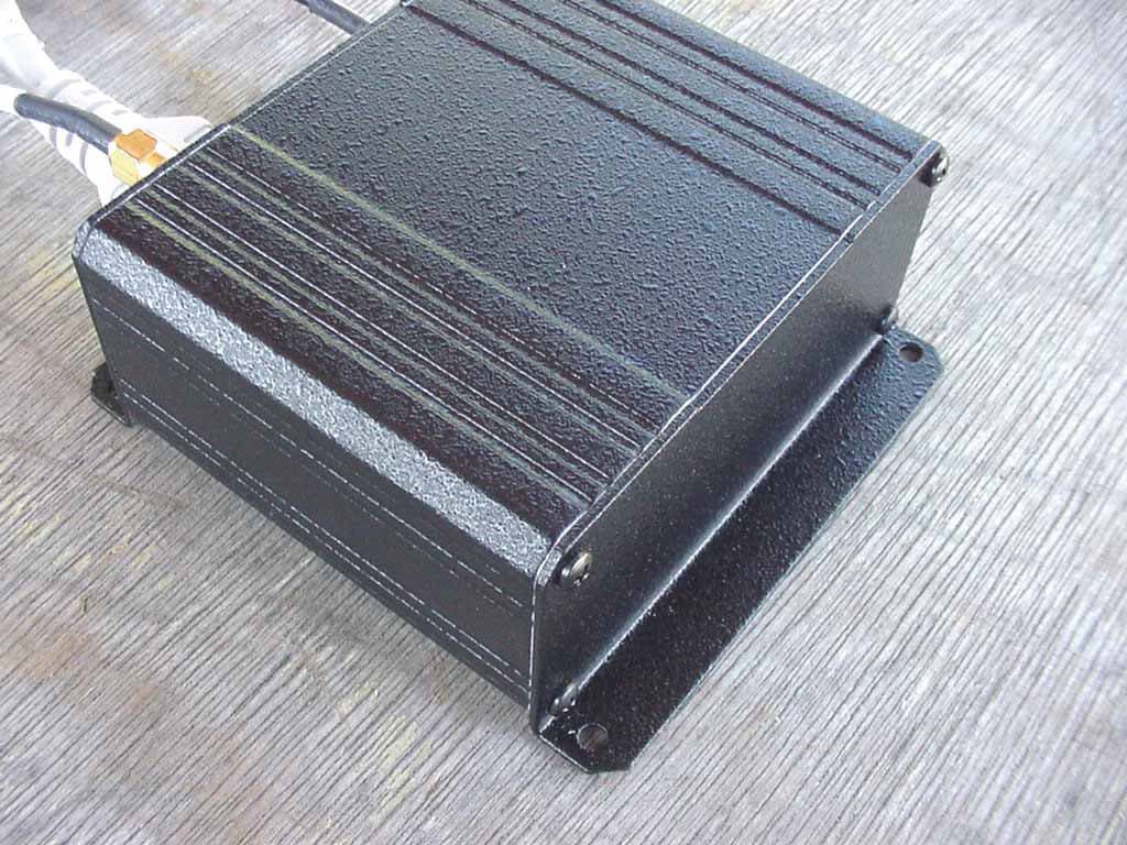
Click to zoom
Application Details
- Equipment Class
- DXX - Part 15 Low Power Communication Device Transmitter
- Date of Grant
- Apr 03, 2002
- Application Purpose
- Original Equipment
- Date of Application
- Apr 03, 2002
- Equipment Note
- Fleet Management System
- Frequency Range
- 903.30000000 - 921.30000000
- Company
- Axiom Navigation, Inc.
- Country
- United States
Documents & Files
Document Text
Text extracted from the exhibit documents filed with the FCC. Open a document above to read the original.
Users Manual
Installation Manual for the FMS2000 Part Number FMS002 Revision date: March 21, 2002 3545 Howard Way, Costa Mesa, CA. 92626 Tel: 714–444-0200 Fax: 714–444-0260 www.axiomnav.com axiom NAVIGATION INC. FMS2500 Installation Manual 2 1. SCOPE This document describes the mechanical and electrical installation requirements for the FMS2000 unit including the GPS/900 MHz dual antenna. This document applies to FMS2000 system part number FMS002. 2. APPLICATION This document is to be used only by professional truck and automotive electrical device installers for the purpose of installing the FMS2000 system. 3.0 ELECTRICAL REQUIREMENTS 3.1 Voltage and Current Requirements for the FMS2000 The FMS unit is designed to operate from nominal +12 volt DC automotive power systems. It will operate normally across a range of 7 to 25 volts. Typical current input is 0.215 amps, with a maximum current of 0.3 amps when maximum input voltage and current loads are applied. The FMS unit should be connected to a fused circuit from the vehicle master fuse panel. This will prevent melted wires or fire in case of a pinched wire that occurs before the FMS unit's input connector. 3.2. Installation Wiring for the FMS2000 Use a minimum of 20 AWG wire to connect the FMS Mobile unit to +12 volt DC vehicle power systems. Do not exceed a wire length of more than 25 feet. Use good installation practices, which protect the wire from sharp metal edges or anything that could abrade or cut through the wire insulation and cause a short. 3.3. LED INDICATOR The LED indicators are a single dual-color LED comprised of RED and GREEN. Since the GREEN is always on, when RED is on the resultant color is ORANGE. Color State Power On Tracking GPS Mobile Unit Location Storing Data Downloading Data None Off N N n/a N N GREEN Solid Y N n/a N N ORANGE Solid Y Y n/a N N ORANGE Blink Y n/a Home N Y ORANGE Blink Y Y Away Y N axiom NAVIGATION INC. FMS2500 Installation Manual 3 4. MECHANICAL REQUIREMENTS 4.1. Mounting Requirements for the FMS2000 The FMS2000 is not environmentally sealed. The installer must select a suitable location protected from excessive dust and liquids, such as drink spills, rain, road spray, or washing equipment. Keep in mind constraints on lengths for power and antenna cabling. The FMS2000 enclosure has a front and rear panel with two mounting holes each. The unit should be mounted securely using star washers or captive nuts to ensure against it vibrating loose. Axiom recommends rechecking the mounting screws or bolts as part of an annual periodic maintenance schedule. 4.2. Mounting Requirements for the Dual Antenna The dual antenna (GPS/900 MHz) is environmentally sealed. Dust or water, such as rain, road spray, or washing equipment does not effect it. ———NOTE ——————— Snow or ice accumulation can significantly attenuate GPS signal strength at the antenna. Bear this in mind when choosing the antenna site. The dual antenna requires a 9-inch diameter minimum metal ground plane for best performance. This is easily achieved by mounting it on a metal vehicle roof or trunk lid. If a metal plane is not used the antenna will still work but the range performance can be greatly reduced. The antenna should not be mounted inside the vehicle as this will greatly reduce both the GPS and 900 MHz signal strength and may result in unreliable operation. The dual antenna comes with 5 meters of RG174 type cable for both the GPS and 900 MHz antennas terminated with SMA type connectors. Care must be taken to match the GPS and Cell radio cables to the identified connectors on the FMS front panel. 5. FCC Certification, Instructions to the User This equipment has been tested and found to comply with the limits for a class B digital device, pursuant to part 15 of the FCC Rules. These limits are designed to provide axiom NAVIGATION INC. FMS2500 Installation Manual 4 reasonable protection against harmful interference in a residential installation. This equipment generates, uses and can radiate radio frequency energy and if not installed and used in accordance with the instructions, may cause harmful interference to radio communications. However, there is no guarantee that interference will not occur in a particular installation. If this equipment does cause harmful interference to radio or television reception, which can be determined by turning the equipment off and on, the user is encouraged to try to correct the interference by one or more of the following measures: • Reorient or relocate the receiving antenna. • Increase the separation between the equipment and receiver. • Connect the equipment into an outlet on a circuit different from that to which the receiver is connected. • Consult the dealer or an experienced radio/TV technician for help. This equipment has been certified to comply with the limits for a class B computing device, pursuant to FCC Rules. In order to maintain compliance with FCC relations, shielded cables must be used with this equipment. Operation with non-approved equipment or unshielded cables is likely to result in interference to radio and TV reception. The user is cautioned that changes and modifications made to the equipment without approval of manufacturer could void the user’s authority to operate this equipment.
Cover Letter(s)
114 OLINDA DRIVE • •• • BREA, CALIFORNIA 92823 • •• • (714) 579-0500 • •• • FAX (714) 579-1850 1 March 20, 2002 Compatible Electronics TCB 114 Olinda Drive Brea, CA 92823 Subject: Request for Certification of the Axiom Navigation, Inc. Fleet Management System Model: FMS2000 FCC ID: PMHFMS2000 Gentlemen: We have enclosed a package for the certification of the Axiom Navigation, Inc. Fleet Management System Model: FMS2000. We have enclosed the completed Form 731 with the applicable exhibits. If you have any questions or need any additional information, please give me a call at (714) 579-0500. Sincerely, Kyle Fujimoto Test Engineer
Cover Letter(s)
114 OLINDA DRIVE • •• • BREA, CALIFORNIA 92823 • •• • (714) 579-0500 • •• • FAX (714) 579-1850 1 March 20, 2002 Federal Communications Commission Equipment Approval Services P.O. Box 358315 Pittsburgh, PA 15251-5315 Subject: Request for withholding from public disclosure the schematic diagrams, system block diagrams, and operational description pursuant to an application for certification. Applicant: Axiom Navigation, Inc. Product: Fleet Management System Model: FMS2000 FCC ID: PMHFMS2000 Gentlemen: As appointed agent for Axiom Navigation, Inc., we would like to request that the schematic diagrams, block diagrams, and operational description submitted with the application for certification be withheld from public disclosure as per Section 0.459 of the FCC Rules. This request is made under the provisions of Section 0.457 (d) of the Commission’s Rules, and Section 522(b)(4) of the Freedom of Information Act. These sections authorize as a withholding from public inspection materials which would be privileged as a matter of law if retained by the person submitting them, and materials which would not customarily be released to the public by that person. If you have any questions or need any additional information, please give me a call at (714) 579-0500. Sincerely, Kyle Fujimoto Test Engineer
Cover Letter(s)
1 Scott McCutchan From: Scott McCutchan [[email protected]] Sent: Wednesday, April 03, 2002 4:27 PM To: [email protected] Subject: FCC ID: PMHFMS2000 Scott McCutchan.vcf In order for processing of this application (FCC ID: PMHFMS2000) to continue, the following issue(s) will have to be addressed: 1) The FCC ID label is not in compliance with section 2.915 of the FCC rules. It should be: FCC ID: PMHFMS2000, not FCC ID #PMHFMS2000. Please submit a corrected label. 2) According to the data sheets in the test report, the fundamental emission was averaged. A Quasi-Peak detector should be used at this frequency. Correpondence to this request may be submitted on our web site under confirmation number PMHFMS2000-1. The item(s) indicated above must be submitted before processing can continue on the above referenced application. Failure to provide the requested information within 60 days of the original e-mail date may result in application dismissal and forfeiture of the filing fee. Also, please note that partial responses increase processing time and should not be submitted. Any questions about the content of this correspondence should be directed to [email protected]. If you have any questions, feel free to contact me. Best regards, Scott McCutchan Operations Manager Compatible Electronics TCB (714) 579-1489 fax (714) 579-1850 http://www.celectronics.com
Cover Letter(s)
Correspondence by Project Project Number: 1017192852 Correspondence Number Memo PMHFMS2000-1 1. The FCC ID has been revised to now read "FCC ID: PMHFMS2000" Please see the attachement uploaded under "revised FCC-ID Label" 2. A revised data sheet has been sent to correctly show it was Quasi-Peaked for the fundamental. The data sheet wasn't chagned before to reflect this.
Test Report
FCC ID: PMHFMS2000 Report No.: B20314D1 114 OLINDA DRIVE, BREA, CALIFORNIA 92823 PHONE: (714) 579-0500 FAX: (714) 579-1850 Page 1 of 16 FCC PART 15, SUBPART C TEST REPORT for FLEET MANAGEMENT SYSTEM Model: FMS2000 Prepared for AXIOM NAVIGATION, INC. 3545 HOWARD WAY COSTA MESA, CALIFORNIA 92626 Prepared by:_____________________ KYLE FUJIMOTO Approved by:____________________ MICHAEL CHRISTENSEN COMPATIBLE ELECTRONICS INC. 114 OLINDA DRIVE BREA, CALIFORNIA 92823 (714) 579-0500 DATE: MARCH 21, 2002 REPORT APPENDICES TOTAL BODY A B C D E PAGES 16 2 2 10 12 2 44 This report shall not be reproduced except in full, without the written approval of Compatible Electronics. FCC ID: PMHFMS2000 Report No.: B20314D1 114 OLINDA DRIVE, BREA, CALIFORNIA 92823 PHONE: (714) 579-0500 FAX: (714) 579-1850 Page 2 of 16 TABLE OF CONTENTS Section / Title PAGE GENERAL REPORT SUMMARY 4 SUMMARY OF TEST RESULTS 4 1. PURPOSE 5 2. ADMINISTRATIVE DATA 6 2.1 Location of Testing 6 2.2 Traceability Statement 6 2.3 Cognizant Personnel 6 2.4 Date Test Sample was Received 6 2.5 Disposition of the Test Sample 6 2.6 Abbreviations and Acronyms 6 3. APPLICABLE DOCUMENTS 7 4. Description of Test Configuration 8 4.1 Description of Test Configuration - EMI 8 4.1.1 Cable Construction and Termination 9 5. LISTS OF EUT, ACCESSORIES AND TEST EQUIPMENT 10 5.1 EUT and Accessory List 10 5.2 EMI Test Equipment 11 6. TEST SITE DESCRIPTION 12 6.1 Test Facility Description 12 6.2 EUT Mounting, Bonding and Grounding 12 7. Test Procedures 13 7.1 Radiated Emissions (Spurious and Harmonics) Test 13 7.2 Band Edge Plots of the Low and High Channels 15 8. CONCLUSIONS 16 FCC ID: PMHFMS2000 Report No.: B20314D1 114 OLINDA DRIVE, BREA, CALIFORNIA 92823 PHONE: (714) 579-0500 FAX: (714) 579-1850 Page 3 of 16 LIST OF APPENDICES APPENDIX TITLE A Modifications to the EUT B Additional Models Covered Under This Report C Diagrams, Charts and Photos • Test Setup Diagrams • Radiated Emissions Photos • Antenna and Effective Gain Factors D Data Sheets E Laboratory Recognitions LIST OF FIGURES FIGURE TITLE 1 Plot Map And Layout of Test Site FCC ID: PMHFMS2000 Report No.: B20314D1 114 OLINDA DRIVE, BREA, CALIFORNIA 92823 PHONE: (714) 579-0500 FAX: (714) 579-1850 Page 4 of 16 GENERAL REPORT SUMMARY This electromagnetic emission test report is generated by Compatible Electronics Inc., which is an independent testing and consulting firm. The test report is based on testing performed by Compatible Electronics personnel according to the measurement procedures described in the test specifications given below and in the "Test Procedures" section of this report. The measurement data and conclusions appearing herein relate only to the sample tested and this report may not be reproduced without the written permission of Compatible Electronics, unless done so in full. This report must not be used to claim product endorsement by NVLAP or any other agency of the U.S. Government. Device Tested: Fleet Management System Model: FMS2000 S/N: N/A Product Description: See Expository Statement. Modifications: The EUT was not modified during the testing. Manufacturer: Axiom Navigation, Inc. 3545 Howard Way Costa Mesa, California 92626 Test Date: March 13, 2002 File # For Canada: IC2154-D Test Specifications : EMI requirements CFR Title 47, Part 15 Subpart C, Sections 15.205, 15.209, and 15.249 Test Procedure: ANSI C63.4: 1992 Test Deviations: The test procedure was not deviated from during the testing. SUMMARY OF TEST RESULTS TEST DESCRIPTION RESULTS 1 Conducted RF Emissions, 450 kHz - 30 MHz This test was not performed because the EUT operates on 12 Vdc only and will not be plugged into the AC public mains. 2 Radiated RF Emissions, 10 kHz - 9300 MHz Complies with the limits of CFR Title 47, Part 15 Subpart C, sections 15.205, 15.209, and 15.249 FCC ID: PMHFMS2000 Report No.: B20314D1 114 OLINDA DRIVE, BREA, CALIFORNIA 92823 PHONE: (714) 579-0500 FAX: (714) 579-1850 Page 5 of 16 1. PURPOSE This document is a qualification test report based on the Electromagnetic Interference (EMI) tests performed on the Fleet Management System Model: FMS2000. The EMI measurements were performed according to the measurement procedure described in ANSI C63.4: 1992. The tests were performed in order to determine whether the electromagnetic emissions from the equipment under test, referred to as EUT hereafter, are within the specification limits defined by CFR Title 47, Part 15, Subpart C, sections 15.205, 15.209, and 15.249. FCC ID: PMHFMS2000 Report No.: B20314D1 114 OLINDA DRIVE, BREA, CALIFORNIA 92823 PHONE: (714) 579-0500 FAX: (714) 579-1850 Page 6 of 16 2. ADMINISTRATIVE DATA 2.1 Location of Testing The EMI tests described herein were performed at the test facility of Compatible Electronics, 114 Olinda Drive, Brea, California 92823. 2.2 Traceability Statement The calibration certificates of all test equipment used during the test are on file at the location of the test. The calibration is traceable to the National Institute of Standards and Technology (NIST) . 2.3 Cognizant Personnel Axiom Navigation, Inc. W.A. Duke, Jr. “Buc” Field and Test Support Manager Chris Foja Engineer Compatible Electronics Inc. Kyle Fujimoto Test Engineer Michael Christensen Test Engineer 2.4 Date Test Sample was Received The test sample was received on March 13, 2002. 2.5 Disposition of the Test Sample The test sample has not been returned to Axiom Navigation, Inc. as of March 14, 2002. 2.6 Abbreviations and Acronyms The following abbreviations and acronyms may be used in this document. RF Radio Frequency EMI Electromagnetic Interference EUT Equipment Under Test P/N Part Number S/N Serial Number HP Hewlett Packard ITE Information Technology Equipment CML Corrected Meter Limit LISN Line Impedance Stabilization Network Tx Transmitter Rx Receiver FCC ID: PMHFMS2000 Report No.: B20314D1 114 OLINDA DRIVE, BREA, CALIFORNIA 92823 PHONE: (714) 579-0500 FAX: (714) 579-1850 Page 7 of 16 3. APPLICABLE DOCUMENTS The following documents a…
Text truncated - open the document above for the full version.
Test Report
RADIATED EMISSIONS (FCC SECTION 15.205 AND 15.247) COMPANY DATE 1/24/02 EUT DUTY CYCLE N/A MODEL PEAK TO AVG N/A S/N TEST DIST. 3 METERS TEST ENGINEER LAB D Frequency Peak Antenna Antenna EUT EUT EUT Antenna Cable Amplifier *Corrected Delta Spec Reading Polar. Height Azimuth Axis Tx Factor Loss Gain Reading ** Limit MHz (dBuV) (V or H) (meters) (deg rees) (X,Y,Z) C hannel (dB) (dB) (dB) (dBuV/m) (dB) (dBuV/m) Comments 903.3000 63.1 QP H 1.0 180 X LOW 22.8 5.1 0.0 91.0 -3.0 94.0 903.3000 62.2 QP V 1.0 180 X LOW 22.8 5.1 0.0 90.1 -3.9 94.0 912.3000 60.3 QP H 2.0 270 X MID 23.2 5.2 0.0 88.7 -5.3 94.0 912.3000 62.8 QP V 1.0 90 X MID 23.2 5.2 0.0 91.2 -2.8 94.0 921.3000 58.2 QP H 1.0 270 X HIGH 23.5 5.4 0.0 87.1 -6.9 94.0 921.3000 64.8 64.7 QP V 1.0 180 X HIGH 23.5 5.4 0.0 93.6 -0.4 94.0 * CORRECTED READING = METER READING + ANTENNA FACTOR + CABLE LOSS - AMPLIFIER GAIN ** DELTA = SPEC LIMIT - CORRECTED READING PAGE 1 Average (A) or Quasi- Peak (QP) N/AAXIOM NAVIGATION, INC.MOBILE UNITFMS2000KYLE FUJIMOTO Doc. No.: EMI_PART15TX-B-0-50 Rev. A 04/11/00
Contact Information
Applicant
Gary Stoermer(Director of Engineering)
Technical Contact
Compatible ElectronicsKyle Fujimoto
[email protected]714-579-0500
114 Olinda Drive · Brea, California · United States
Test Firm
Compatible ElectronicsScott McCutchan
714-579-0500Fax: 714-579-1850
Technical Specifications
| # | Rule Parts | Frequency Range | Power Output |
|---|---|---|---|
| 1 | 15C | 903.3 MHz - 921.3 MHz | - |
Other Applications from Axiom Navigation, Inc.
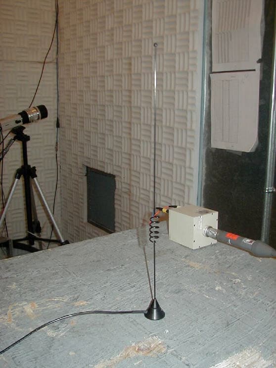
PMHFMS3500
Jan 13, 2002Fleet Management System
Equipment Class
TNB - Licensed Non-Broadcast Station Transmitter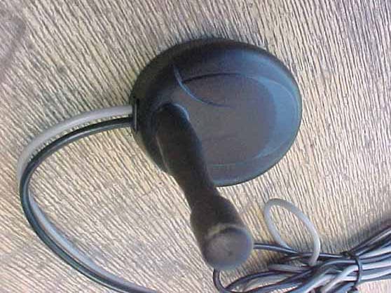
PMHFMS2500
Jun 06, 2001Fleet Management System
Equipment Class
DXX - Part 15 Low Power Communication Device Transmitter