PMHFMS3500Fleet Management System
Axiom Navigation, Inc.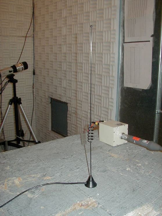
Click to zoom
Application Details
- Equipment Class
- TNB - Licensed Non-Broadcast Station Transmitter
- Date of Grant
- Jan 13, 2002
- Application Purpose
- Original Equipment
- Date of Application
- Jul 20, 2001
- Equipment Note
- Fleet Management System
- Frequency Range
- 824.01000000 - 848.97000000
- Company
- Axiom Navigation, Inc.
- Country
- United States
Documents & Files
Document Text
Text extracted from the exhibit documents filed with the FCC. Open a document above to read the original.
Users Manual
Installation Manual for the FMS3500 Part Number FMS10A Revision date: June 26, 2001 800 South Harbor Boulevard Anaheim, California 92805 USA Tel: 714–780–5900 Fax: 714–780–0078 www.axiomnav.com aiom xxxNAVIGATION INC. axiom NAVIGATION INC. FMS3500 Installation Manual2 1. SCOPE This document describes the mechanical and electrical installation requirements for the FMS3500 unit including the cellular and GPS/900 MHz dual antenna. This document applies to FMS3500 part number FMS10A. 2. APPLICATION This document is to be used only by a professional truck and automotive electrical device installers for the purpose of installing the FMS3500 system. 3.0 ELECTRICAL REQUIREMENTS 3.1Specification Requirements for the FMS3500 The FMS3500 was designed to the specifications of SAE J1455, Surface Vehicle Recommended Practice; (R) Joint SAE/TMC Recommended Environmental Practices for Electronic Equipment Design (Heavy-Duty Trucks) 3.2. Voltage and Current Requirements for the FMS3500 The FMS unit is designed to operate from nominal +12 or +24 volt DC automotive power systems. It will operate normally across a range of 9 to 32 volts. Typical current input is 0.1 amps, with a maximum current of 2 amps when maximum input voltage and current loads are applied. The FMS unit contains an automatically re-settable fuse device for self protection. The FMS unit is protected against damage from reverse polarity connections. Reverse polarity should not be applied for more than five minutes to prevent component damage. The fuse is heat activated by over-current caused by reverse polarity or a failed internal component. The fuse can be reset by disconnecting the input power for several minutes to allow it to cool off. If upon re-connection of the power the Green LED does not come on then the FMS unit should be returned for repair. The FMS unit should be connected to a fused circuit from the vehicle master fuse panel in addition to the FMS unit internal fuse. This will prevent melted wires or fire in case of a pinched wire which occurs before the FMS unit input connector. Power transient protection and over-voltage protection is also provided by the FMS power supply. The FMS unit will survive being connected to continuous 150 volts, and will survive power spikes up to 630 volts. axiom NAVIGATION INC. FMS3500 Installation Manual3 3.3. Installation Wiring for the FMS3500 Use a minimum of 20 AWG wire to connect the FMS Mobile unit to +12/24 volt DC vehicle power systems. Do not exceed a wire length of more than 25 feet. Use good installation practices which protect the wire from sharp metal edges or anything that could abrade or cut through the wire insulation and cause a short. 3.4. LED INDICATOR There are two LED indicators on the FMS front panel: Green LED; • Normally on when power is applied. Indicates that the power supply is providing regulated +5 Volts to the internal circuitry. • Blinks quickly when serial data is being sent to the 900 MHz transmitter or RJ-45 serial port. This should occur at the end of a trip upon return to the home location or when using the FMS debug port with a computer. Failure Diagnoses: • Green LED stays off; No +5 volt regulated power. Verify there is +12/24 volt input to the FMS unit, check input power connector for good connection. Remove and re-install I/O connector to reset unit. If there is proper unit operation via the FMS debug port (RJ-45 connector), then the LED may be failed. Red LED; • Normally off when power is applied. • Blinks quickly when serial data and control messages are being sent to the cellular transmitter. This should occur when initializing the microburst cellular radio and when microburst transmission are taking place. 4. MECHANICAL REQUIREMENTS 4.1. Mounting Requirements for the FMS3500 The FMS3500 is not environmentally sealed. The installer must select a suitable location protected from excessive dust and liquids, such as drink spills, rain, road spray, or washing equipment. Keep in mind constraints on lengths for power and antenna cabling. The FMS3500 enclosure has a front and rear panel with two mounting holes each. The unit should be mounted securely using star washers or captive nuts to ensure against it vibrating loose. Axiom recommends rechecking the mounting screws or bolts as part of an annual periodic maintenance schedule. The FMS unit is certified to meet SAE J1455 standards for shock and vibration of electronic equipment for truck cab mounting locations. axiom NAVIGATION INC. FMS3500 Installation Manual4 4.2. Antenna Mounting Requirements Three antennas are required for FMS3500 operation; GPS, 800 MHz cellular band and 900 MHz. 4.2.1. GPS/900 MHz Dual Antenna Mounting Requirements The dual antenna (GPS/900 MHz) is environmentally sealed. Dust or water, such as rain, road spray, or washing equipment does not effect it. ———NOTE ——————— Snow or ice accumulation can significantly attenuate GPS signal strength at the antenna. Bear this in mind when choosing the antenna site. The dual antenna requires a 9-inch diameter minimum metal ground plane for best performance. This is easily achieved by mounting it on a metal vehicle roof or trunk lid. If a metal plane is not used the antenna will still work but the range performance can be greatly reduced. The antenna should not be mounted inside the vehicle as this will greatly reduce both the GPS and 900 MHz signal strength and may result in unreliable operation. The dual antenna comes with 5 meters of RG174 type cable for both the GPS and 900 MHz antennas terminated with SMA type connectors. Care must be taken to match the GPS and Cell radio cables to the identified connectors on the FMS front panel. 4.2.2. 800 MHz cellular Antenna Mounting Requirements Only the following antennas are approved for use with the FMS3500 system: • Maxrad, PN BMMG8350 , magnetic mount; 1/4 wave, Unity gain • Maxrad, PN 8353, magnetic mount; 1/2 wave, 3 dB gain • Antenna Specialists, PN APD827.1M; on-glass, 1/4 wave Unity gain (2 d…
Text truncated - open the document above for the full version.
Cover Letter(s)
FEDERAL COMMUNICATIONS COMMISSION WASHINGTON, D.C. 20554 GRANT OF EQUIPMENT AUTHORIZATION Certification Attention: Ron Blanchard NOT TRANSFERABLE EQUIPMENT AUTHORIZATION is hereby issued to the named GRANTEE, and is VALID ONLY for the equipment identified hereon for use under the Commission's Rules and Regulations listed below. Standard Communications Corporation 1111 Knox Street Torrance,CA 90502 Date of Grant: 05/01/2001 Application Dated: 01/31/2001 FCC IDENTIFIER APV09001 Name of Grantee Standard Communications Corporation Equipment Class: Licensed Non-Broadcast Station Transmitter Notes: Grant Notes FCC Rule Parts Frequency Range (MHZ) Output Watts Frequency Tolerance Emission Designator 22 824.01 - 848.97 3 2.5 PM 36K0F1D Output power is at the antenna terminal. This module is for OEM integration only, using with a 2.5 dBi antenna, as indicated in the Certification filing. Devices operating with this module must be installed to provide a separation distance of 20 cm or more between the antenna and persons for satisfying the mobile transmitter requirements of 2.1091. The antenna must be mounted without a ground plane and must not be co-located with other transmitters. OEM integrators and end-users must be provided with appropriate instructions for satisfying RF exposure compliance. All other configurations that do not satisfy the above requirements are required to obtain separate Certification. Mail To: EA99920 Page 1 of 1 7/21/01https://gullfoss2.fcc.gov/cgi-bin/ws.exe/prod/oet/forms/misc/Grant_Form.hts?application_id=99
Cover Letter(s)
FEDERAL COMMUNICATIONS COMMISSION WASHINGTON, D.C. 20554 GRANT OF EQUIPMENT AUTHORIZATION Type Acceptance Attention: Ron Blanchard NOT TRANSFERABLE EQUIPMENT AUTHORIZATION is hereby issued to the named GRANTEE, and is VALID ONLY for the equipment identified hereon for use under the Commission's Rules and Regulations listed below. Standard Communications Corporation 1111 Knox Street Torrance,CA 90502 Date of Grant: 06/10/1996 Application Dated: 04/11/1996 FCC IDENTIFIER APV0896 Name of Grantee Standard Communications Corporation Equipment Class: Licensed Non-Broadcast Station Transmitter Notes: Grant Notes FCC Rule Parts Frequency Range (MHZ) Output Watts Frequency Tolerance Emission Designator 22.901(d) 824 - 849 3 0.00025 % 40K0F1D Mail To: Morton Flom, M Flom Associates, Inc. 3356 N San Marcos Place, Suite Chandler, AZ 85224-1571 9604198315167001 Page 1 of 1 7/21/01https://gullfoss2.fcc.gov/cgi-bin/ws.exe/prod/oet/forms/misc/Grant_Form.hts?application_id=14
Cover Letter(s)
Re: FCC ID PMHFMS3500 Applicant: Axiom Navigation, Inc. Correspondence Reference Number: 21184 731 Confirmation Number: EA101776 1) It is not clear whether the tests were performed with a ground plane, as recommended in the User Manual for the 1/4 wave antennas. Please clarify this issue. Response: The boilerplate report test setup and statement was not updated to reflect the setup with the ground plane. A revise MPE report has been provided with changes on page 5 of 6. 2) It is not understood why the antenna with the highest gain (Maxrad, BMMG8353, 5 dBi) produced some of the lowest readings. Please explain this. Response: The incorrect gain was listed on the MPE report and MPE data. The correct gain is 3 dBi per the specification document provided by the customer (This is also indicated on the model number by having a 3 at then end of it). Correction has been made on the MPE data and on page 3 of 6 of the MPE revised report.
ID Label/Location Info
axiom Navigation, IncPOSITION YOURSELF WITH US1 Figure 15 ß Install SMA hardware using color coded lock washers and hex nuts on the three SMA connectors. Tighten. Figure 16 ß Apply FCC Certification Label to bottom side of Extruded Box approximately where shown. NOTE: Orient so that FCC Label is “right reading” with coax connectors to SMA Connectors toward this end Use “gold” Washer & Nut Use “silver” Washer & Nut Use “red” Washer & “gold” Nut axiom Navigation, IncPOSITION YOURSELF WITH US2 right. Figure 17 ß Print two copies of Top Assembly Labels. Boards inside unit and Top Assembly Label are now “matched” so enclosure and internal boards must remain together through the remainder of the assembly / test process. ß Apply one of the Top Assembly Labels to the top side of Extruded Box approximately where shown. NOTE: Orient so that the Top Assembly Label is “right reading” with coax connectors to left. Figure 18 Tape second Top Assembly Label to Unit as shown. Label must remain w/Unit through the remainder of the production process. Second Label will be applied to outside of shipping container. Move to Unit Level Test.
RF Exposure Info
File: R39897 Page 1 of 17 RF Hazard Evaluation Report on the Fleet Management System Model: FMS3500 GRANTEE:Axiom Navigation, Inc. 800 South Harbor Blvd, Suite 201 Anaheim, CA 92805 TEST SITE:Elliott Laboratories, Inc. 684 W. Maude Ave Sunnyvale, CA 94086 REPORT DATE:June 12, 2001 FINAL TEST DATE:June 7, 2001 AUTHORIZED SIGNATORY:______________________________ Juan Martinez EMC Engineer This report shall not be reproduced, except in its entirety, without the written approval of Elliott Laboratories, Inc. Elliott Laboratories, Inc. -- EMC DepartmentTest Report Report Date: June 13, 2001 File: J43762Page 2 of 6 pages TABLE OF CONTENTS COVER PAGE ........................................................................................................................................................... 1 TABLE OF CONTENTS ............................................................................................................................................2 GENERAL INFORMATION ....................................................................................................................................3 SCOPE..........................................................................................................................................................................4 OBJECTIVE................................................................................................................................................................4 TEST RESULTS..........................................................................................................................................................5 S ECTION 2.1091: RADIOFREQUENCY RADIATION EXPOSURE EVALUATION: MOBILE DEVICES....................5 EQUIPMENT UNDER TEST (EUT) DETAILS......................................................................................................6 SUPPORT EQUIPMENT ........................................................................................................................................6 EXTERNAL I/O CABLING ....................................................................................................................................6 TEST SOFTWARE ..................................................................................................................................................6 TEST MODES..........................................................................................................................................................6 EXHIBIT 1: Test Equipment Calibration Data ...................................................................................................1 EXHIBIT 2: Test Measurement Data ..................................................................................................................2 Elliott Laboratories, Inc. -- EMC DepartmentTest Report Report Date: June 13, 2001 File: J43762Page 3 of 6 pages GENERAL INFORMATION Applicant:Axiom Navigation, Inc. 800 South Harbor Blvd, Suite 201 Anaheim, CA 92805 Technical Description The FMS3500 will be used with either the CMM 8600 or the CMM 8700 Cellular Radio Module, which have been FCC approved. The FMS3500 is a vehicle location and tracking Fleet Management System (FMS). The FMS3500 is typically installed under the dash of a vehicle. Data is retrieved through either the 900 MHz (Section 15.249) transmitter or the CMM cellular modules. Axom Navigation will be using the following antennas with the FMS3500 unit. A) Maxrad (M/N: BMMG8350), magnetic mount, ¼ wave, 0 dBi B) Maxrad (M/N: BMMG8353), magnetic mount, ½ wave, 5 dBi C) Antenna Specialists (M/N: APD827.1M), window mount antenna, 2 dBi D) All is (M/N: GPS-GC), magnetic mount, 3 dBi The antennas will usually be mounted 5-10 feet diagonally from a driver and external to the passenger compartment or cab (i.e, on the roof of a truck or car). In some cases it may be mounted above a seated passenger, but again, on the outside of the vehicle (maybe 8-10 inches from all persons). Frequency Range CMM 8600 and 8600 radio modules: Transmitter: 824.01 – 848.97 MHz Receiver: 869.01 – 893.97 MHz Range of Operation Power 3-Watt maximum power output Elliott Laboratories, Inc. -- EMC DepartmentTest Report Report Date: June 13, 2001 File: J43762Page 4 of 6 pages SCOPE RF Hazard Evaluation testing was performed for the equipment mentioned in this report. OET Bulletin 65 or the ANSI/IEEE C95.3, "IEEE Recommended Practice for the Measurement of Potentially Hazardous Electromagnetic Fields - RF and Microwave" were used as a test procedure guideline to perform the required test. MPE measurements were performed for this product. The intentional radiator above was tested in a simulated typical installation to demonstrate compliance with the relevant FCC performance and procedural standards. OBJECTIVE The primary objective of the manufacturer is compliance with Section 2.1091. Certification of these devices is required as a prerequisite to marketing as defined in Section 2.1033. Certification is a procedure where the manufacturer or a contracted laboratory makes measurements and submits the test data and technical information to FCC. FCC issues a grant of equipment authorization and a certification number upon successful completion of their review of the submitted documents. Once the equipment authorization has been obtained, the label indicating compliance must be attached to all identical units subsequently manufactured. Elliott Laboratories, Inc. -- EMC DepartmentTest Report Report Date: June 13, 2001 File: J43762Page 5 of 6 pages TEST RESULTS Section 2.1091: Radiofrequency radiation exposure evaluation: Mobile devices. Test Setup: MPE Evaluation was performed using the OET Bulletin 65 or the ANSI/IEEE C95.3, "IEEE Recommended Practice for the Measurement of Potentially Hazardous Electromagnetic Fields - RF and Microwave" test procedure, for mobile devices. The EUT was set to transmit at maximum power, this was verified with a spectrum analyz…
Text truncated - open the document above for the full version.
RF Exposure Info
In response to your questions: 1.) It is expected that the original unit will perform the same - except for radiated spurious emissions (RSE) in the new package. Therefore, the test for RSE needs to be re-done. 2.) The unit is to be tested in the complete new package. If this new package has two separate transmitters, then the SAR / MPE evaluation would be based on the levels produced by both transmitters. 3.) The Grant will state the maximum antenna gain and types that be used based on the information you have supplied. (I am sorry for the delay in providing this response - I have been out of the office.) >>> <[email protected]> 03/06/01 12:10PM >>> In a message dated 3/5/01 11:32:18 AM Pacific Standard Time, [email protected] writes: << 1.) The application for unit FCC ID: APV0896 was submitted on April 11, 1996 and approved on June 10, 1996. This was before the Rules were adopted for RF exposure. Therefore, any application using this device must respond to the RF exposure requirements: include SAR measurements for portable units and MPE measurements for mobile units. (See Sections 2.1091 and 2.1093 of FCC R&R). This is true regardless of whether the original unit was configured as a "Module". 2.) The compliance with the RF exposure requirements must be demonstrated for each antenna type (to be) used. >> Hello Mr. Coperic, Thank you so much for your detailed response. I do have a couple more questions to clarify. We understand that the device will have to be evaluated for MPE/SAR. Do the rest of the tests need to be repeated, such as radiated emissions, conducted antenna emissions, etc.? This cell module will be placed in a "fleet management system" which is installed trucks in order to track them. The system contains a 900 MHz transmitter and a GPS receiver, as well as the cell module. Can we just perform the tests on the system without the cell module installed, and then just submit the SAR/MPE measurement data with the application, since the cell module was already approved in 1996? Or should the tests on the system be performed with the cell module installed and active? The customer had stated that the buyer would select which antenna he needs, and in your response you mention that each antenna would have to be evaluated for SAR/MPE. Does the customer have any options, other than to test each antenna? Any further guidance you can provide would be greatly appreciated. Thank you, Kyle Fujimoto Subj: Re: Cellular Modems and Bluetooth Date: 3/26/01 12:07:58 PM Pacific Standard Time From: [email protected] (Frank Coperich) To: [email protected] Page 1 of 2 Saturday, July 21, 2001 America Online: CEkyle [email protected] Compatible Electronics -- Brea Division ----------------------- Headers -------------------------------- Return-Path: <[email protected]> Received: from rly-xb05.mx.aol.com (rly-xb05.mail.aol.com [172.20.105.106]) by air-xb04.mail.aol.com (v77_r1.36) with ESMTP; Mon, 26 Mar 2001 15:07:58 -0500 Received: from gatekeeper2.fcc.gov (gatekeeper2.fcc.gov [192.104.54.4]) by rly-xb05.mx.aol.com (v77_r1.36) with ESMTP; Mon, 26 Mar 2001 15:07:18 -0500 Received: by gatekeeper2.fcc.gov; id PAA05675; Mon, 26 Mar 2001 15:07:16 -0500 (EST) Received: from unknown(165.135.237.22) by gatekeeper2.fcc.gov via smap (V5.5) id xma005565; Mon, 26 Mar 01 15:06:27 -0500 Received: from ROUTE_A-Message_Server by fcc.gov with Novell_GroupWise; Mon, 26 Mar 2001 15:06:28 -0500 Message-Id: <[email protected]> X-Mailer: Novell GroupWise 5.5.2 Date: Mon, 26 Mar 2001 15:05:51 -0500 From: "Frank Coperich" <[email protected]> To: <[email protected]> Subject: Re: Cellular Modems and Bluetooth Mime-Version: 1.0 Content-Type: text/plain; charset=US-ASCII Content-Transfer-Encoding: quoted-printable Content-Disposition: inline Page 2 of 2 Saturday, July 21, 2001 America Online: CEkyle
Test Report
FCC ID: PMHFMS3500 Report No.: B10614D1 114 OLINDA DRIVE, BREA, CALIFORNIA 92823 PHONE: (714) 579-0500 FAX: (714) 579-1850 Page 1 of 18 FCC PART 15, SUBPART C AND PART 22 TEST REPORT for FLEET MANAGEMENT SYSTEM Model: FMS3500 Prepared for AXIOM NAVIGATION, INC. 800 SOUTH HARBOR BOULEVARD ANAHEIM, CALIFORNIA 92805 COMPATIBLE ELECTRONICS INC. 114 OLINDA DRIVE BREA, CALIFORNIA 92823 (714) 579-0500 DATE: JUNE 18, 2001 REPORT APPENDICES TOTAL BODY A B C D E PAGES 18 2 2 12 34 2 70 This report shall not be reproduce d exce pt in full, without the written approval of Compatible Elec tronics. FCC ID: PMHFMS3500 Report No.: B10614D1 114 OLINDA DRIVE, BREA, CALIFORNIA 92823 PHONE: (714) 579-0500 FAX: (714) 579-1850 Page 2 of 18 TABLE OF CONTENTS Section / Title PAGE GENERAL REPORT SUMMARY 4 SUMMARY OF TEST RESULTS 5 1. PURPOSE 6 2. ADMINISTRATIVE DATA 7 2.1 Location of Testing 7 2.2 Traceability Statement 7 2.3 Cognizant Personnel 7 2.4 Date Test Sample was Received 7 2.5 Disposition of the Test Sample 7 2.6 Abbreviations and Acronyms 7 3. APPLICABLE DOCUMENTS 8 4. Description of Test Configuration 9 4.1 Description of Test Configuration - EMI 9 4.1.1 Cable Construction and Termination 11 5. LISTS OF EUT, ACCESSORIES AND TEST EQUIPMENT 12 5.1 EUT and Accessory List 12 5.2 EMI Test Equipment 13 6. TEST SITE DESCRIPTION 14 6.1 Test Facility Description 14 6.2 EUT Mounting, Bonding and Grounding 14 7. Test Procedures 15 7.1 Radiated Emissions (Spurious and Harmonics) Test 15 7.2 Band Edge Plots of the Low and High Channels 17 8. CONCLUSIONS 18 FCC ID: PMHFMS3500 Report No.: B10614D1 114 OLINDA DRIVE, BREA, CALIFORNIA 92823 PHONE: (714) 579-0500 FAX: (714) 579-1850 Page 3 of 18 LIST OF APPENDICES APPENDIX TITLE A Modifications to the EUT B Additional Models Covered Under This Report C Diagrams, Charts and Photos • Test Setup Diagrams • Radiated Emissions Photos • Antenna and Effective Gain Factors D Data Sheets E Laboratory Recognitions LIST OF FIGURES FIGURE TITLE 1 Plot Map And Layout of Test Site FCC ID: PMHFMS3500 Report No.: B10614D1 114 OLINDA DRIVE, BREA, CALIFORNIA 92823 PHONE: (714) 579-0500 FAX: (714) 579-1850 Page 4 of 18 GENERAL REPORT SUMMARY This electromagnetic emission test report is generated by Compatible Electronics Inc., which is an independent testing and consulting firm. The test report is based on testing performed by Compatible Electronics personnel according to the measurement procedures described in the test specifications given below and in the "Test Procedures" section of this report. The measurement data and conclusions appearing herein relate only to the sample tested and this report may not be reproduced without the written permission of Compatible Electronics, unless done so in full. This report must not be used to claim product endorsement by NVLAP or any other agency of the U.S. Government. Device Tested: Fleet Management System Model: FMS3500 S/N: N/A Product Description: See Expository Statement. Modifications: The EUT was not modified during the testing. Manufacturer: Axiom Navigation, Inc. 800 South Harbor Boulevard Anaheim, California 92805 Test Dates: May 21, 25 and 31, 2001 File # For Canada: IC2154-D Test Specifications : EMI requirements CFR Title 47, Part 15 Subpart C, Sections 15.205, 15.209, and 15.249; CFR Title 47 Part 22 Section 22.917 (e); Test Procedure: ANSI C63.4: 1992 Test Deviations: The test procedure was not deviated from during the testing. FCC ID: PMHFMS3500 Report No.: B10614D1 114 OLINDA DRIVE, BREA, CALIFORNIA 92823 PHONE: (714) 579-0500 FAX: (714) 579-1850 Page 5 of 18 SUMMARY OF TEST RESULTS TEST DESCRIPTION RESULTS 1 Conducted RF Emissions, 450 kHz - 30 MHz This test was not performed because the EUT operates on 12 Vdc only and will not be plugged into the AC public mains. 2 Radiated RF Emissions on the Digital Portion and Transmitter, 10 kHz - 9300 MHz Complies with the limits of CFR Title 47, Part 15 Subpart C, sections 15.205, 15.209, and 15.249 3 Radiated Spurious Emissions on the Cellular Phone Module Complies with the limits of CFR Title 47, Part 22 Section 22.917 (e) FCC ID: PMHFMS3500 Report No.: B10614D1 114 OLINDA DRIVE, BREA, CALIFORNIA 92823 PHONE: (714) 579-0500 FAX: (714) 579-1850 Page 6 of 18 1. PURPOSE This document is a qualification test report based on the Electromagnetic Interference (EMI) tests performed on the Fleet Management System Model: FMS3500. The EMI measurements were performed according to the measurement procedure described in ANSI C63.4: 1992. The tests were performed in order to determine whether the electromagnetic emissions from the equipment under test, referred to as EUT hereafter, are within the specification limits defined by CFR Title 47, Part 15, Subpart C, sections 15.205, 15.209, and 15.249; and CFR Title 47, Part 22, Section 22.917 (e). FCC ID: PMHFMS3500 Report No.: B10614D1 114 OLINDA DRIVE, BREA, CALIFORNIA 92823 PHONE: (714) 579-0500 FAX: (714) 579-1850 Page 7 of 18 2. ADMINISTRATIVE DATA 2.1 Location of Testing The EMI tests described herein were performed at the test facility of Compatible Electronics, 114 Olinda Drive, Brea, California 92823. 2.2 Traceability Statement The calibration certificates of all test equipment used during the test are on file at the location of the test. The calibration is traceable to the National Institute of Standards and Technology (NIST) . 2.3 Cognizant Personnel Axiom Navigation, Inc. W.A. Duke, Jr. “Buc” Field and Test Support Manager Jeff Burd FMS Project Manger Compatible Electronics Inc. Kyle Fujimoto Test Engineer Scott McCutchan Lab Manager 2.4 Date Test Sample was Received The test sample was received on May 21, 2001. 2.5 Disposition of the Test Sample The test sample was returned to Axiom Navigation, Inc. on May 31, 2001. 2.6 Abbreviations and Acronyms The following abbreviations and acronyms may be used in this document. RF Radio Frequency EMI Electromagnetic Interference EUT Equipment Under Test P/N Part Number S/N Serial Number HP Hewlett Packar…
Text truncated - open the document above for the full version.
Contact Information
Applicant
Gary Stoermer(Director of Engineering)
Test Firm
Compatible ElectronicsScott McCutchan
714-579-0500Fax: 714-579-1850
Technical Specifications
| # | Rule Parts | Frequency Range | Power Output | Emission | Tolerance |
|---|---|---|---|---|---|
| 1 | 22.901(d) | 824.01 MHz - 848.97 MHz | 3 W | 36K0F1D | 2.5000000000 ppm |
Other Applications from Axiom Navigation, Inc.
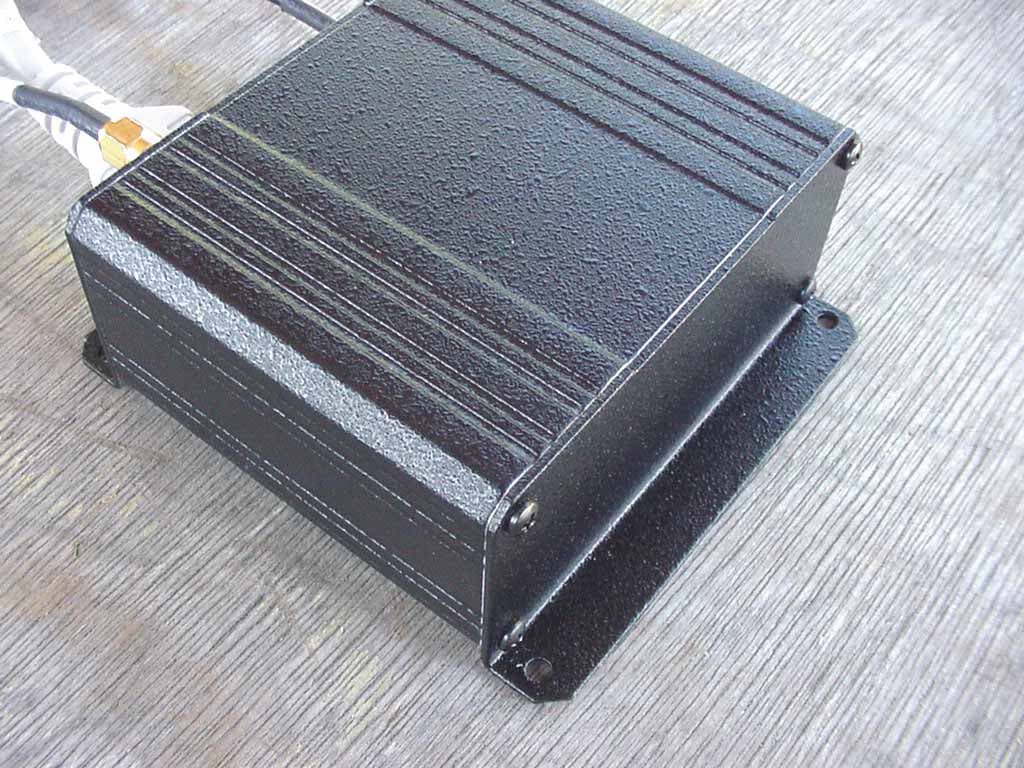
PMHFMS2000
Apr 03, 2002Fleet Management System
Equipment Class
DXX - Part 15 Low Power Communication Device Transmitter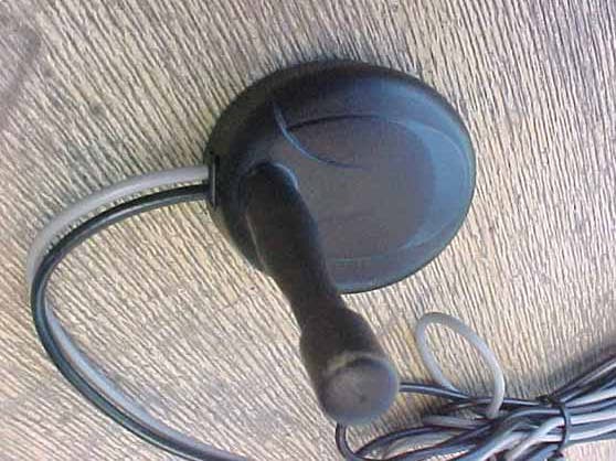
PMHFMS2500
Jun 06, 2001Fleet Management System
Equipment Class
DXX - Part 15 Low Power Communication Device Transmitter