PMJT1500Digital Audio Transmitter
Amphony Corp.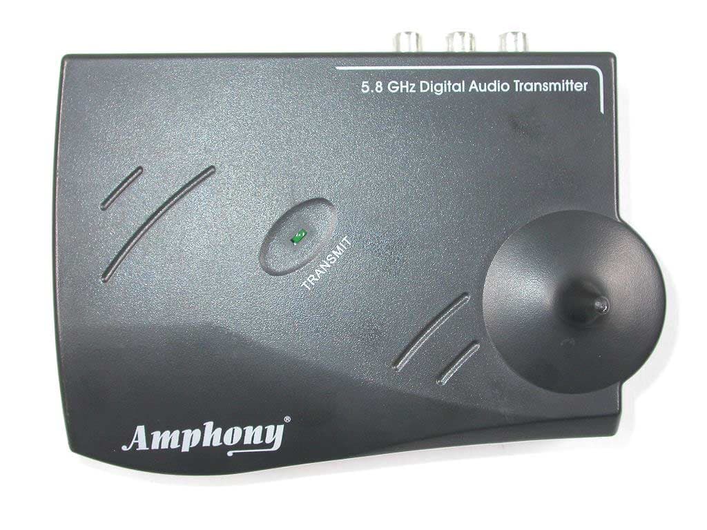
Click to zoom
Application Details
- Equipment Class
- DXX - Part 15 Low Power Communication Device Transmitter
- Date of Grant
- Nov 24, 2005
- Application Purpose
- Original Equipment
- Date of Application
- Nov 24, 2005
- Equipment Note
- Digital Audio Transmitter
- Frequency Range
- 5725.00000000 - 5875.00000000
- Company
- Amphony Corp.
- Country
- United States
Documents & Files
Document Text
Text extracted from the exhibit documents filed with the FCC. Open a document above to read the original.
Users Manual
RR User and Installation Guide 5.8 GHz DIGITAL Wireless Audio Transmitter / Receiver Model 1500 User and Installation Guide Page 1 RR Step 1 Connecting the transmitter The transmitter connects to a line-out interface via the supplied RCA cable. Most audio devices provide a line-out interface. If no line-out interface is available, the transmitter can also be connected to other audio outputs by using an appropriate adapter. It should be noted that the audio level of the audio output should conform to the standard line output level (V ± 2.8 V maximum). pp If the audio level is too low, the dynamic range of the transmitter is not fully used. If the audio level is too high, clipping at high audio levels may occur. If clipping occurs, use an adjustable output (such as a headphones output) instead and a suitable adapter (such as a Y adapter). If the transmitter is connected to an amplified speaker output, an attenuator is required to lower the audio level to the maximum permitted transmitter audio level. Connect the DC power input with the supplied AC adapter. The use of a surge protector is recommended to protect the transmitter from power surges. L AUDIO IN DATA OUT R DC 9V LR AUDIO LINE OUT Audio Source Transmitter DC 9 V 300 mA Power outlet AC adapter ATTENTION! Never connect the DATA OUT output to an audio source since this may damage both the transmitter and the audio equipment ! Unpacking: Check that this package contains: One 5.8 GHz Digital Audio transmitter, one 5.8 GHz Digital Audio receiver, two AC adapters, two dual RCA audio cables. User and Installation Guide Page 2 RR Step 2 Placing the transmitter The operating range essentially depends on how many obstacles there are between the transmitter and the receiver. Therefore, it should be carefully considered where to place the transmitter. Below, two examples are given. In the first example, there are 4 walls between the transmitter and the receiver. The transmission may be interrupted. By locating the transmitter such as in the second example, reliable transmission to all of the 6 rooms is possible. Also, the elevation of the transmitter as well as the presence of reflecting walls will influence the range. It is suggested to experiment in order to find the best location for the transmitter. If sufficient coverage cannot be achieved by changing the location of the transmitter, then the use of RangeBooster transmitters is suggested. These RangeBooster transmitters are available as an accessory for your 5.8 GHz Digital Wireless Audio Transmitter / Receiver from Amphony and can be located in areas where signal reception is difficult. RangeBooster transmitters connect to the DATA OUT output of the transmitter via a cable and receive the signal in a digital format without any degradation. Any number of RangeBooster transmitters can be used to extend the coverage area. Note: The operating range of each RangeBooster transmitter is identical to the operating range of the primary transmitter. Example 1: Poorly chosen transmitter location Example 2: Improved transmitter location User and Installation Guide Page 3 RR Step 3 Connecting the receiver The receiver connects to a line-in interface via the supplied RCA cable. Most audio devices, such as amplifiers, provide a line-in interface. If no line-in interface is available, the receiver can also be connected to other audio inputs by using an appropriate adapter. It should be noted that the maximum audio level of the receiver output is 1 Vrms (V ± 1.4 V maximum). pp Ensure that the connected audio device will accept this audio level. Connect the DC power input with the supplied AC adapter. The use of a surge protector is recommended to protect the receiver from power surges which may damage the receiver or may cause audio dropouts. ATTENTION! Do not connect the receiver audio output directly to passive speakers or other low impedance drains as this may damage the receiver! The receiver audio output cannot drive passive speakers or headphones directly. An external amplifier is required. LR AUDIO LINE IN Audio Drain (Amplifier) Receiver DC 9 V 300 mA Power outlet AC adapter DC 9V L R User and Installation Guide Page 4 RR Step 4 Operating the transmitter and receiver After powering up the transmitter, the transmit light will light for approximately 5 seconds while the transmitter initializes. After initialization, the transmit light will go out. Once audio is detected at the audio input, the transmit light will light and the transmitter will transmit the audio signal. When no audio is present anymore, the transmitter will go into standby mode after approximately 1 minute. The transmit light will go out. During standby mode, no signal is transmitted. Once the receiver is powered up and a valid audio signal is detected, audio will be output at the receiver line out. When no valid audio signal is received, the receiver audio output will be muted and the receiver will go into standby mode. If the transmitter or receiver are not used for an extended period of time, remove the AC adapters from the power outlet. 5.8 GHz Digital Audio Transmitter5.8 GHz Digital Audio Transmitter RR TR A N S M IT TR A N S M IT Transmit light User and Installation Guide Page 5 RR Problems and Solutions Table For more information, including a detailed troubleshooting guide, visit the Amphony web site at: www.amphony.com What Is Happening Possible WhyWhat To Do Transmit light of transmitter does not light when DC power is applied Faulty AC adapter or faulty power outlet Check the power outlet and the AC adapter, if possible, check for the correct voltage of the adapter. No audio present at audio input Check the audio connection to the transmitter and ensure that there is audio present. Transmit light goes out after 5 seconds and does not light again Transmitter hung upDisconnect and then reconnect DC power. Receiver hung upDisconnect and then reconnect DC power. No audio at receiver Strong interferenceIn some cases, there ma…
Text truncated - open the document above for the full version.
Cover Letter(s)
Letter Of Agency June 30, 2005 PHOENIX TEST-LAB GmbH Kˆnigswinkel 10 D-32825 Blomberg To Whom It May Concern: Please be advised that Amphony Corp. authorizes Senton GmbH to act on our behalf, until otherwise notified, for applications submitted to PHOENIX TEST-LAB GmbH. We certify that we are not subject to denial of federal benefits, that includes FCC benefits, pursuant to Section 5301 of the Anti-Drug Abuse ACT of 1988, U.S.C. 862. Further, no party, as defined in 47 CFR 1.2002(b), to the application is subject to denial of federal benefits, that includes FCC benefits. Thank you for your attention to this matter. Jens Kurrat President
Cover Letter(s)
Request for Confidentiality in accordance with 47 CFR 0.459 Date: 03 November 2005 PHOENIX TEST-LAB GmbH Kˆnigswinkel 10 D32825 Blomberg Germany RE: Certification Application FCC ID: PMJT1500 Please be advised that the following information is to be held confidential on behalf of Amphony Corp.: • Schematics • Block Diagram • Technical Description The application contains technical information which Amphony Corp. deems to be trade secrets and proprietary. If made public, the information might be used to the disadvantage of the applicant in the market place. Thank you for your attention to this matter.
External Photos
FCC ID PMJT1500 FCC ID PMJT1500 FCC ID PMJT1500 FCC ID PMJT1500
ID Label/Location Info
FCC ID PMJT1500
Internal Photos
FCC ID PMJT1500 FCC ID PMJT1500 FCC ID PMJT1500
Test Report
Senton GmbH Aeussere Fruehlingstrasse 45 D-94315 Straubing Note: The test data of this report is related only to the individual item which has been tested. This report shall not be reproduced except in full extent without the written approval of the testing laboratory. Test Report No. 50104-050463 (Edition 2) Page 1 of 29 Pages Straubing, 18 October 2005 T E S T - R E P O R T No. 50104-050463 (Edition 2) for Model 1500 Audio Transmitter & Receiver Applicant: Amphony (Deutschland) GmbH Test Specifications: FCC Code of Federal Regulations, CFR 47, Part 15, Sections 15.107, 15.109, 15.205, 15.207, 15.215 and 15.249 Senton GmbH Aeussere Fruehlingstrasse 45 D-94315 Straubing Test Report No. 50104-050463 (Edition 2) Page 2 of 29 Pages Table of Contents 1 Description of the Equipment Under Test (EUT) ........................................................ 3 2 Administrative Data..................................................................................................... 4 3 Identification of the Test Laboratory ........................................................................... 5 4 Summary .................................................................................................................... 6 5 Operation Mode and Configuration of EUT................................................................. 7 6 Measurement Procedures........................................................................................... 8 6.1 Bandwidth Measurements .................................................................................... 8 6.2 Conducted AC Powerline Emission .................................................................... 10 6.3 Radiated Emission in Fully or Semi Anechoic Room.......................................... 12 6.4 Radiated Emission at Open Field Test Site........................................................ 14 7 Photographs Taken During Testing .......................................................................... 15 8 Test Results for Transmitter ..................................................................................... 19 8.1 Occupied Bandwidth........................................................................................... 20 8.2 Restricted Bands of Operation ........................................................................... 22 8.3 Conducted Powerline Emission Measurement 150 kHz to 30 MHz................... 23 8.4 Radiated Emission Measurement 6 MHz to 40 GHz ......................................... 24 9 Test Results for Receiver.......................................................................................... 25 9.1 Conducted Powerline Emission Measurement 150 kHz to 30 MHz................... 26 9.2 Radiated Emission Measurement 30 MHz to 40 GHz ....................................... 27 10 Referenced Regulations ........................................................................................... 28 11 Charts taken during testing ....................................................................................... 29 Senton GmbH Aeussere Fruehlingstrasse 45 D-94315 Straubing Test Report No. 50104-050463 (Edition 2) Page 3 of 29 Pages 1 Description of the Equipment Under Test (EUT) General data of EUT Type designation 1 : Model 1500 Parts 2 : Serial number(s): Prototype Manufacturer: Amphony (Deutschland) GmbH Type of equipment: Audio Transmitter & Receiver Version: FCC ID: N/A Additional parts/accessories: AC Adaptors for Transmitter & Receiver Technical data of EUT Application frequency range: 5725 ñ 5875 MHz Frequency range: Operating frequency: 5800 MHz Type of modulation: FM Pulse train: Pulse width: Number of RF-channels: 1 Channel spacing: N.A. Designation of emissions 3 : 20M0F3D Type of antenna: Integrated Size/length of antenna: N/A Connection of antenna: detachable not detachable Type of power supply: AC supply Specifications for power supply: nominal voltage: 115 V minimum voltage: N/A V maximum voltage: N/A V nominal frequency: 60 Hz 1 Type designation of the system if EUT consists of more than one part. 2 Type designations of the parts of the system, if applicable. 3 Also known as "Class of Emission". Senton GmbH Aeussere Fruehlingstrasse 45 D-94315 Straubing Test Report No. 50104-050463 (Edition 2) Page 4 of 29 Pages 2 Administrative Data Application details Applicant (full address): Amphony (Deutschland) Gmbh Annenstrafle 26 D- 10179 Berlin Contact person: Jens Kurrat Contract identification: --- Receipt of EUT: 29 July 2005 Date(s) of test: August to October 2005 Note(s): Report details Report number: 50104-050463 Edition: 2 Issue date: 18 October 2005 Senton GmbH Aeussere Fruehlingstrasse 45 D-94315 Straubing Test Report No. 50104-050463 (Edition 2) Page 5 of 29 Pages 3 Identification of the Test Laboratory Details of the Test Laboratory Company name: Senton GmbH EMI/EMC Test Center Address: Aeussere Fruehlingstrasse 45 D-94315 Straubing Germany Laboratory accreditation: DAR-Registration No. DAT-P-171/94-02 FCC test site registration number 90926 Industry Canada test site registration: IC 3050 Contact person: Mr. Johann Roidt Phone: (+49) (0)9421 5522-0 Fax: (+49) (0)9421 5522-99 Senton GmbH Aeussere Fruehlingstrasse 45 D-94315 Straubing Test Report No. 50104-050463 (Edition 2) Page 6 of 29 Pages 4 Summary Summary of test results The tested sample complies with the requirements set forth in the Code of Federal Regulations CFR 47, Part 15, Sections 15.107, 15.109, 15.205, 15.207, 15.215 and 15.249 of the Federal Communication Commission (FCC). Personnel involved in this report Laboratory Manager: Mr. Johann Roidt Responsible for testing: Mr. Johann Roidt Responsible for test report: Mr. Johann Roidt Senton GmbH Aeussere Fruehlingstrasse 45 D-94315 Straubing Test Report No. 50104-050463 (Edition 2) Page 7 of 29 Pages 5 Operation Mode and Configuration of EUT Operation Mode(s) Audio signal 100 mV / 1 kHz at Transmitter input Configuration(s) of EUT Stand alone List of port…
Text truncated - open the document above for the full version.
Test Setup Photos
Senton GmbH Aeussere Fruehlingstrasse 45 D-94315 Straubing Test Report No. 50104-050463 (Edition 1) Page 16 of 29 Pages Test setup for conducted AC powerline emission measurement Senton GmbH Aeussere Fruehlingstrasse 45 D-94315 Straubing Test Report No. 50104-050463 (Edition 1) Page 17 of 29 Pages Test setup for radiated emission measurement (fully anechoic room) Senton GmbH Aeussere Fruehlingstrasse 45 D-94315 Straubing Test Report No. 50104-050463 (Edition 1) Page 18 of 29 Pages Test setup for radiated emission measurement (fully anechoic room) - continued -
Contact Information
Applicant
Jeff Barrett
Technical Contact
Senton GmbHJohann Roidt
[email protected]+49 9421 552213
Aeussere Fruehlingstrasse 45 · Straubing · Germany
Test Firm
TUV SUD Product Service GmbH PS-EMC-STRRainer Heller
Technical Specifications
| # | Rule Parts | Frequency Range | Power Output |
|---|---|---|---|
| 1 | 15C | 5.72 GHz - 5.88 GHz | - |
Other Applications from Amphony Corp.
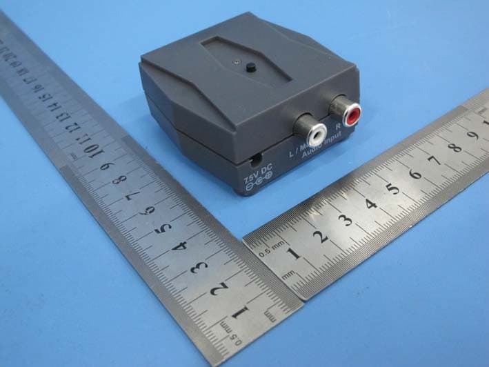
PMJTX2
Jan 19, 2015Audio transmitter
Equipment Class
DSS - Part 15 Spread Spectrum Transmitter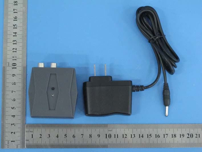
PMJRX2
Jan 19, 2015Audio Receiver
Equipment Class
DSS - Part 15 Spread Spectrum Transmitter
PMJB300
Mar 03, 2014BlueFidelity Bluetooth Amplifier
Equipment Class
DSS - Part 15 Spread Spectrum Transmitter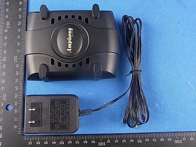
PMJRX1
Oct 17, 2011Audio Receiver
Equipment Class
DSS - Part 15 Spread Spectrum Transmitter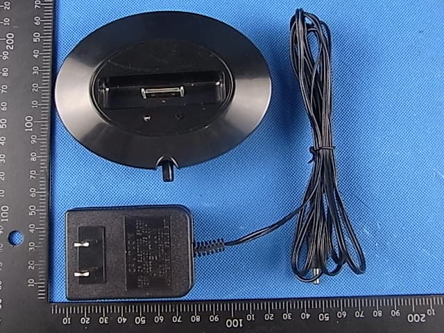
PMJTX1
Oct 17, 2011Audio Transmitter
Equipment Class
DSS - Part 15 Spread Spectrum Transmitter