PMJTX2Audio transmitter
Amphony Corp.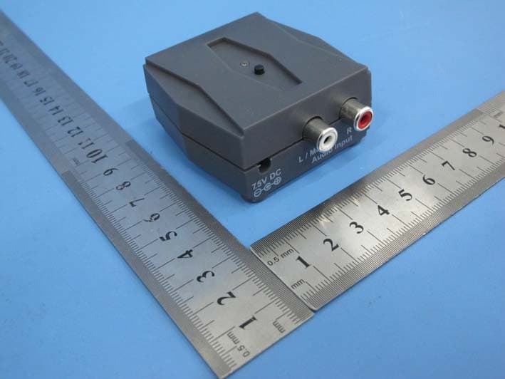
Click to zoom
Application Details
- Equipment Class
- DSS - Part 15 Spread Spectrum Transmitter
- Date of Grant
- Jan 19, 2015
- Application Purpose
- Original Equipment
- Date of Application
- Jan 18, 2015
- Equipment Note
- Audio transmitter
- Frequency Range
- 2402.00000000 - 2480.00000000
- Company
- Amphony Corp.
- Country
- United States
Documents & Files
Document Text
Text extracted from the exhibit documents filed with the FCC. Open a document above to read the original.
Users Manual
R User and Installation Guide Wireless Subwoofer Kit Introduction The iFinity wireless subwoofer kit solves your wiring dilemma when setting up a subwoofer or a pair of active speakers. Now you can easily place your subwoofer anywhere in your home or use a pair of speakers on your patio or by your pool. Unpacking Verify that this box contains: one wireless audio transmitter one wireless audio receiver two 7.5 Volt AC adapters (wallwarts) two RCA audio cables Installation Connect the first RCA audio cable to the transmitter audio input and your audio source. If you are connecting to a single (mono) audio output, simply leave the second audio plug unconnected. Then connect the first wallwart to the transmitter power input. Next, connect the second RCA cable with the audio input of your active speakers, subwoofer or power amplifier. If you are connecting to a subwoofer, simply leave the second RCA plug unconnected. Finally, connect the second wallwart to the receiver power input. Pairing In order to stream audio, the receiver must first be paired with the audio transmitter. First, press the pairing button of the audio transmitter. The transmitter network status light will start flashing quickly. Limited warranty WHAT YOUR WARRANTY COVERS This warranty extends only to the original user of the equipment (“you”, ”your”) and is limited to the purchase price of each part. Amphony and its affiliated companies (”we”, ”our”, ”us”) warrant this Wireless Subwoofer Kit against defects in materials or workmanship as follows. LABOR: For a period of ninety (90) days from the original date of purchase, if we determine that the equipment is defective subject to the limitations of this warranty, we will replace it at no charge for labor. We warrant any such work done against defects in materials or workmanship for the remaining portion of the original warranty period. PARTS: For a period of one (1) year from the original date of purchase, we will supply, at no charge, new or rebuilt replacement parts in exchange for parts we determine are defective subject to the limitations of this warranty. We warrant any such replacement parts against defects in materials or workmanship for the remaining portion of the original warranty period. Note: ”Parts” means items included in this package. It does not include other parts purchased separately. WHAT YOUR WARRANTY DOES NOT COVER This warranty does not cover consumer instruction, physical setup or adjustment of any consumer electronic equipment, or signal transmission problems. This warranty does not cover cosmetic damage, damage due to the affixing of any attachment not provided with the product, loss of parts, connecting the product to any but the specified receptacles, lightning, electrical surges, fire, flood, or other acts of God, accident, misuse, abuse, repair or alteration by other than authorized service personnel, negligence, commercial or institutional use, or improper or neglected maintenance. This warranty does not cover equipment sold AS IS or WITH ALL FAULTS, equipment removal or reinstallation, shipping damage if the equipment was not packed and shipped in the manner we prescribe, nor equipment purchased, serviced, or operated outside the contiguous United States of America. LEGAL LIMITATIONS REPLACEMENT AS PROVIDED UNDER THIS WARRANTY IS YOUR EXCLUSIVE REMEDY. WE SHALL NOT BE HELD LIABLE FOR ANY INCIDENTAL OR CONSEQUENTIAL DAMAGES FOR BREACH OF ANY EXPRESSED OR IMPLIED WARRANTY ON THIS EQUIPMENT, NOR FOR ANY INCIDENTAL OR CONSEQUENTIAL DAMAGES RESULTING FROM THE USE OF, OR INABILITY TO USE, THIS EQUIPMENT. UNDER NO CIRCUMSTANCES SHALL OUR LIABILITY, IF ANY, EXCEED THE PURCHASE PRICE PAID FOR THIS EQUIPMENT, EXCEPT TO THE EXTENT PROHIBITED BY APPLICABLE LAW. EXCEPT AS PROVIDED HEREIN, WE MAKE NO WARRANTIES, EXPRESS OR IMPLIED, INCLUDING WARRANTIES OF MERCHANTABILITY AND FITNESS FOR A PARTICULAR PURPOSE. WE RESERVE THE RIGHT TO REFUSE TO HONOR THIS WARRANTY IF WE DETERMINE ANY OF THE ABOVE EXCEPTIONS TO HAVE CAUSED THIS EQUIPMENT NOT TO HAVE PERFORMED PROPERLY. THIS WARRANTY SHALL BE VOID IF ANY FACTORY-APPLIED IDENTIFICATION MARK, INCLUDING BUT NOT LIMITED TO SERIAL NUMBERS AND WARRANTY LABELS, HAS BEEN ALTERED OR REMOVED. THIS WARRANTY SHALL ALSO BE VOID IF THE TRANSMITTER OR AMPLIFIER HAVE BEEN OPENED BY AN UNAUTHORIZED PERSON. This warranty gives you specific legal rights which may vary from state to state. Some states do not allow the exclusion or limitation of incidental or consequential damages, or allow limitations on the duration of an implied warranty, so those limitations may not apply to you. Note: No responsibility is assumed for the presence of interference outside of Amphony’s control, such as other transmitters or cordless phones, which may hamper proper signal reception. Please refer to the above drawing to locate the pairing button. Now press the pairing button of the audio receiver within 5 minutes. Once the receiver locks to the transmitter signal, both the transmitter and receiver network status light will light continuously. You now should be able to hear the audio. You can pair up to 4 wireless receivers with one transmitter. Description of the network status light Flashing Slowly: Not paired Flashing Quickly: Pairing Mode Always On: Audio is being streamed Network status light Pairing button .5V DC7L / MonoR Audio Input Transmitter Connections LR AUDIO LINE OUT Audio Source DC 7.5V Power outlet AC adapter See note Note: Leave right RCA plug unconnected if you have a mono source. Copyright (C) 2014 Amphony. All rights reserved. The information contained herein is subject to change without notice. Revisions may be issued to advise of such changes and/or additions. All product names, trade names, or corporate names mentioned in this document are acknowledged to be the proprietary property of the registered owners. .5V DC7L / MonoR Audio Output Receiver Connections LR AUDIO LINE IN Active speaker, subwoofer or power amplifier DC 7.5V …
Text truncated - open the document above for the full version.
Cover Letter(s)
SCS-F18: Project and Product Certification Representative Authorization Letter Page 1 of 3 Rev 5.0 775 Montague Expressway Milpitas, CA 95035 Tel: 408-526-1188 Fax: 408-526-1088 Email: [email protected] Project and Product Certification Representative Authorization Letter Reason for Amendment (current / obsolete) Revision History Approved Date From To Initial Release (obsolete) 1.0 1.0 Nov-14-2006 Revised wording (obsolete) 1.0 2.0 Sept–25-2007 Updated company template (obsolete) 2.0 3.0 Jan-31-2012 Updated letter information (obsolete) 3.0 4.0 May-23-2014 Added FCC ID field (current) 4.0 5.0 Sept 16 2014 SCS-F18: Project and Product Certification Representative Authorization Letter Page 2 of 3 Rev 5.0 Amphony Corp. 2014-12-25 To: SIEMIC, INC. 775 Montague Expressway, Milpitas, CA 95035 USA Dear Sir/Madam, Re: Product Certification Representative Authorization Letter We, _____ Amphony Corp. _____hereby authorize SIEMIC, Inc. to act as a Certification Body for certifying for the following project(s): ( Audio transmitter, TX2) FCC ID: PMJTX2 Sincerely, Client’s signature Client’s name / title Jens Kurrat / President Contact information / address 1006 S. Raven Rd., Shorwood, IL 60432, USA
Cover Letter(s)
Amphony Corp. SCS-F19: Confidentiality Request Letter Page 1 of 2 Rev 3.0 775 Montague Expressway Milpitas, CA 95035 Tel: 408-526-1188 Fax: 408-526-1088 Email: [email protected] Confidentiality Request Letter Reason for Amendment (current / obsolete) Revision History Approved Date From To Initial Release (obsolete) 1.0 1.0 Nov-14-2006 Adding CFR 2.459 (obsolete) 1.0 2.0 August – 11 - 2008 Updated company template & Added text box (current) 2.0 3.0 Jan-31-2012 Amphony Corp. SCS-F19: Confidentiality Request Letter Page 2 of 2 Rev 3.0 2014-12-25 To: Federal Communications Commission Authorization and Evaluation Division 7435 Oakland Mills Road Columbia, MD Subject: Permanent Confidentiality Request for FCC ID: PMJTX2 We hereby request confidential treatment of information accompanying this application as outlined below: - Block Diagram - Schematics - Operational Description The above materials contain trade secrets and proprietary information not customarily released to the public. The public disclosure of these materials may be harmful to the applicant and provide unjustified benefits to its competitors. The applicant understands that pursuant to Section 0.457 & 0.459 of the Rules, disclosure of this application and all accompanying documentation will not be made before the date of the Grant for this application. Sincerely, Client’s signature Client’s name / title Jens Kurrat / President Contact information / address 31006 S. Raven Rd., Shorwood, IL 60432, USA
External Photos
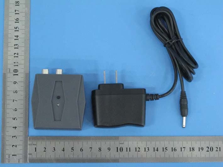
Report No.: TBMTI-FCC143046 Page: 3 of 8 TB-RF-075-1.0 Appendix III EUT External Photographs Photo 1 Appearance of EUT Photo 2 Appearance of EUT Report No.: TBMTI-FCC143046 Page: 4 of 8 TB-RF-075-1.0 Photo 3 Appearance of EUT Photo 4 Appearance of EUT
ID Label/Location Info
Appendix I FCC ID Label FCC ID: PMJTX2 This device complies with part 15 of the FCC Rules: Opration is subject to the following two conditions: (1) This device may not cause harmful interference, and (2) This device must accept any interference received, including interference that may cause undesired operation. Audio transmitter Amphony Corp. Model: TX2
ID Label/Location Info
Report No.: TBMTI-FCC143046 Page: 2 of 8 TB-RF-075-1.0 Appendix II ID Label Location ID LOCATION
Internal Photos
Report No.: TBMTI-FCC143046 Page: 5 of 8 TB-RF-075-1.0 Appendix IV EUT Internal Photographs Photo 5 Internal of EUT Photo 6 Appearance of PCB BT(2.4G) Antenna Report No.: TBMTI-FCC143046 Page: 6 of 8 TB-RF-075-1.0 Photo 7 Appearance of PCB Photo 8 Appearance of PCB
RF Exposure Info
Shenzhen Toby Technology Co., Ltd. Report No.: TBMTI-MPE143047 Page: 1 of 3 TB-RF-074-1.0 1A/F., Bldg.6, Yusheng Industrial Zone, The National Road No.107 Xixiang Section 467, Xixiang, Bao’an, Shenzhen, China Tel: +86 75526509301 Fax: +86 75526509195 RF Exposure Evaluation FCC ID: PMJTX2 1. Client Information Applicant : Amphony Corp. Address : 1006 S. Raven Rd., Shorwood, IL 60432, USA Manufacturer : Suzhou Feiye Electronics Address : No. 18 Xinzhong Rd., Wuzhong District, Suzhou, China 2. General Description of EUT EUT Name : Audio Transmitter Models No. : TX2 Model Difference : N/A Product Description : Operation Frequency: Bluetooth:2402~2480MHz Number of Channel: Bluetooth:79 Channels Max Peak Output Power: 8-DPSK: 3.025dBm (Conducted Power) Antenna Gain: 0 dBi PCB Antenna Modulation Type: GFSK 1Mbps(1 Mbps) π/4-DQPSK(2 Mbps) 8-DPSK(3 Mbps) Power Supply : DC Voltage supplied from AC/DC adapter Power Rating : Input: 100~240V, 50/60Hz, 0.3A Output: 7.5V,1000mA Connecting I/O Port(S) : Please refer to the User's Manual Note: More test information about the EUT please refer the RF Test Report. Report No.: TBMTI-MPE143047 Page: 2 of 3 TB-RF-074-1.0 SAR Test Exclusion Calculations 1. FCC: According to KDB 447498 D01 Mobile and Portable Devices RF Exposure Procedures and Equipment Authorization Policies v05r02. (1) Clause 4.3: General SAR test reduction and exclusion guidance Sub clause 4.31: Standalone SAR test exclusion considerations 1) The 1-g and 10-g SAR test exclusion thresholds for 100 MHz to 6GHz at test separation distance≤5 mm are determined by: [(max. power of channel, including tune-up tolerance, mW)/(min. test separation, mm)]*[√f (GHz) ] ≤3.0 for 1-g SAR [(max. power of channel, including tune-up tolerance, mW)/(min. test separation, mm)]*[√f (GHz) ] ≤7.5.0 for 10-g SAR Report No.: TBMTI-MPE143047 Page: 3 of 3 TB-RF-074-1.0 2. Calculation: Test separation: 5mm Bluetooth Mode (GFSK) Frequency (GHz) Conducted Power (dBm) Ant Gain (dBi) Turn-up Power Tolerance (dB) Max power of tune up tolerance (mw) Calculation Value Threshold Value 2.402 1.806 0 ±1 1.908 0.591 3.0 2.441 2.515 0 ±1 2.246 0.702 3.0 2.480 3.001 0 ±1 2.512 0.791 3.0 Bluetooth Mode (8-DPSK) Frequency (GHz) Conducted Power (dBm) Ant Gain (dBi) Turn-up Power Tolerance (dB) Max power of tune up tolerance (mw) Calculation Value Threshold Value 2.402 1.761 0 ±1 1.888 0.585 3.0 2.441 2.436 0 ±1 2.206 0.689 3.0 2.480 3.025 0 ±1 2.526 0.796 3.0 So standalone SAR measurements are not required.
Test Report
Shenzhen Toby Technology Co., Ltd. Report No.: TBMTI-FCC143046 Page: 1 of 75 TB-RF-074-1.0 1A/F., Bldg.6, Yusheng Industrial Zone, The National Road No.107 Xixiang Section 467, Xixiang, Bao’an, Shenzhen, China Tel: +86 75526509301 Fax: +86 75526509195 FCC Radio Test Report FCC ID: PMJTX2 Original Grant Report No. : TBMTI-FCC143046 Applicant : Amphony Corp. Equipment Under Test (EUT) EUT Name : Audio Transmitter Model No. : TX2 Brand Name : N/A Receipt Date : 13.Dec.2014 Test Date : 15.Dec.2014 Issue Date : 25.Dec.2014 Standards : FCC Part 15: 2014, Subpart C(15.247) Test Method : ANSI C63.4:2003 Conclusions : PASS In the configuration tested, the EUT complied with the standards specified above, The EUT technically complies with the FCC requirements Test/Witness Engineer : Approved& Authorized : This report details the results of the testing carried out on one sample. The results contained in this test report do not relate to other samples of the same product. The manufacturer should ensure that all products in series production are in conformity with the product sample detailed in the report. Report No.: TBMTI-FCC143046 Page: 2 of 75 TB-RF-074-1.0 Contents CONTENTS ............................................................................................................................................. 2 1. GENERAL INFORMATION ABOUT EUT ............................................................................. 4 1.1 Client Information ................................................................................................................. 4 1.2 General Description of EUT (Equipment Under Test) ................................................... 4 1.3 Block Diagram Showing the Configuration of System Tested ...................................... 5 1.4 Description of Support Units .............................................................................................. 6 1.5 Description of Test Mode .................................................................................................... 6 1.6 Description of Test Software Setting ................................................................................ 7 1.7 Test Facility ........................................................................................................................... 8 2. TEST SUMMARY ....................................................................................................................... 9 3. CONDUCTED EMISSION TEST ........................................................................................... 10 3.1 Test Standard and Limit .................................................................................................... 10 3.2 Test Setup ........................................................................................................................... 10 3.3 Test Procedure ................................................................................................................... 10 3.4 Test Equipment Used ........................................................................................................ 11 3.5 EUT Operating Mode ........................................................................................................ 11 3.6 Test Data ............................................................................................................................. 11 4. RADIATED EMISSION TEST ................................................................................................ 14 4.1 Test Standard and Limit .................................................................................................... 14 4.2 Test Setup ........................................................................................................................... 15 4.3 Test Procedure ................................................................................................................... 16 4.4 EUT Operating Condition ................................................................................................. 16 4.5 Test Equipment .................................................................................................................. 17 5. RESTRICTED BANDS REQUIREMENT ............................................................................. 32 5.1 Test Standard and Limit .................................................................................................... 32 5.2 Test Setup ........................................................................................................................... 32 5.3 Test Procedure ................................................................................................................... 32 5.4 EUT Operating Condition ................................................................................................. 33 5.5 Test Equipment .................................................................................................................. 33 6. NUMBER OF HOPPING CHANNEL .................................................................................... 46 6.1 Test Standard and Limit .................................................................................................... 46 6.2 Test Setup ........................................................................................................................... 46 6.3 Test Procedure ................................................................................................................... 46 6.4 EUT Operating Condition ................................................................................................. 46 6.5 Test Equipment .................................................................................................................. 46 6.6 Test Data ............................................................................................................................. 46 7. AVERAGE TIME OF OCCUPANCY ........................................…
Text truncated - open the document above for the full version.
Test Setup Photos
Report No.: TBMTI-FCC143046 Page: 7 of 8 TB-RF-075-1.0 Appendix V EUT Test Photographs 15C Test Setup Photo of Setup for Radiated Emission (Above 1 GHz) Photo of Setup for Radiated Emission (Below 1 GHz) Report No.: TBMTI-FCC143046 Page: 8 of 8 TB-RF-075-1.0 Photo of Setup for Conducted Emission
Contact Information
Applicant
Jeff Barrett
Test Firm
Shenzhen Toby Technology Co., Ltd.Justin Zhang
Technical Specifications
| # | Rule Parts | Frequency Range | Power Output |
|---|---|---|---|
| 1 | 15C | 2.40 GHz - 2.48 GHz | 2.00 mW |
Other Applications from Amphony Corp.
PMJRX2
Jan 19, 2015Audio Receiver
Equipment Class
DSS - Part 15 Spread Spectrum Transmitter
PMJB300
Mar 03, 2014BlueFidelity Bluetooth Amplifier
Equipment Class
DSS - Part 15 Spread Spectrum Transmitter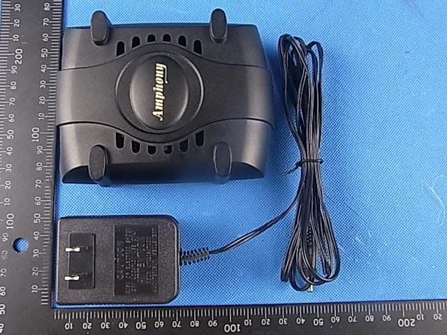
PMJRX1
Oct 17, 2011Audio Receiver
Equipment Class
DSS - Part 15 Spread Spectrum Transmitter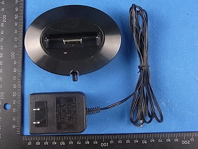
PMJTX1
Oct 17, 2011Audio Transmitter
Equipment Class
DSS - Part 15 Spread Spectrum Transmitter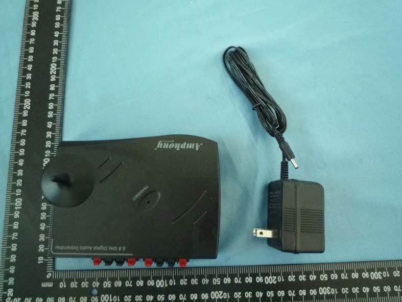
PMJT400
Mar 16, 20115.8 GHz Multi Channel Audio Transmitter
Equipment Class
DXX - Part 15 Low Power Communication Device Transmitter