PMJT2000Wireless Headphone System
Amphony Corp.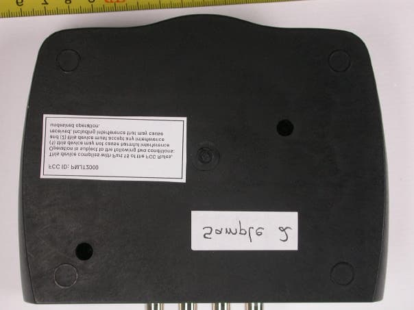
Click to zoom
Application Details
- Equipment Class
- DXX - Part 15 Low Power Communication Device Transmitter
- Date of Grant
- Aug 27, 2003
- Application Purpose
- Original Equipment
- Date of Application
- Aug 27, 2003
- Equipment Note
- Wireless Headphone System
- Frequency Range
- 2448.59000000 - 2448.59000000
- Company
- Amphony Corp.
- Country
- United States
Documents & Files
Document Text
Text extracted from the exhibit documents filed with the FCC. Open a document above to read the original.
Users Manual
R User and Installation Guide 2.4 GHz DIGITAL Wireless Headphones Model 2000 User and Installation Guide Page 1 R Step 1 Connecting the transmitter The transmitter provides 2 digital interfaces and 1 analog interface to connect to an audio source. The transmitter accepts a digital audio signal at both the electrical and optical digital interface. By using one of the digital interfaces, audio data can be fed directly into the transmitter. This bypasses the digital-to-analog and analog-to- digital conversion and thereby eliminates audio distortion. Many HiFi components provide a digital audio interface. The format of the digital audio which is fed into the transmitter must be uncompressed S/PDIF stereo data at a sampling rate of 32 kHz, 44.1 kHz or 48 kHz. Compressed multichannel audio data (which is provided by many DVD players) cannot be processed by the transmitter. In such case, set the format of the DVD player audio interface to uncompressed stereo data. Connect the digital audio output of the audio source with the digital audio interface of the transmitter by using an RCA cable if the electrical interface is used. If the optical interface is used, connect the transmitter by using an optical audio cable (not included). Connect the DC power input with the supplied AC adapter. The use of a surge protector is recommended to protect the transmitter from power surges and audio dropouts. Digital Audio Interface Analog Audio Interface DC Power Input Analog audio can be fed into the transmitter via the analog audio interface. Analog audio is converted to digital audio inside the transmitter by an analog- to-digital converter. The analog audio interface can be connected to a line out interface which is provided by most audio sources. The analog audio interface can also be connected to other analog outputs by using an appropriate adapter. The transmitter will accept maximum audio levels between 0.2 Vrms and 10 Vrms. Prior to operating the transmitter, the analog audio interface should be set to the correct audio level by adjusting the analog audio interface level control (see page 7). Unpacking:Check that this package contains: One set of 2.4 GHz Digital Wireless Headphones, one 2.4 GHz Digital Audio transmitter, one AC adapter, one dual RCA audio cable, four NiMh batteries. DC 9VDC9V DATA OUT DATA OUT LR ANALOG IN LR ANALOG IN DIGITAL INDIGITALIN LR AUDIO LINE OUT Analog Audio Source Power outlet AC adapter DC 9V 400 mA DC 9VDC9V DATA OUT DATA OUT LR ANALOG IN LR ANALOG IN DIGITAL INDIGITALIN DIGITAL OUT Digital Audio Source Power outlet AC adapter DC 9V 400 mA User and Installation Guide Page 2 R Using the electrical digital audio interface Using the analog audio interface R R Page 3 Step 2 Placing the transmitter The operating range essentially depends on how many obstacles there are between the transmitter and the headphones. Therefore, it should be carefully considered where to place the transmitter. Below, two examples are given. In the first example, there are 4 walls between the transmitter and the receiver. The transmission may be interrupted. By locating the transmitter such as in the second example, reliable transmission to all of the 6 rooms is possible. Also, the elevation of the transmitter as well as the presence of reflecting walls will influence the range. It is suggested to experiment in order to find the best location for the transmitter. If sufficient coverage cannot be achieved by changing the location of the transmitter, then the use of RangeBooster transmitters is suggested. These RangeBooster transmitters are available as an accessory for your 2.4 GHz Digital Wireless Headphones from Amphony and can be located in areas where signal reception is difficult. RangeBooster transmitters connect to the DATA OUT output of the transmitter and receive the signal in a digital format without any degradation. Any number of RangeBooster transmitters can be used to extend the operating range almost indefinitely. Example 1:Poorly chosen transmitter location Example 2:Improved transmitter location User and Installation Guide R User and Installation Guide Page 4 R Step 3 Charging the batteries Prior to operating the headphones, the batteries have to be charged. Four rechargeable NiMh batteries are supplied. Insert two of the batteries into the battery charging bays of the transmitter. The two lights “Battery 1” and “Battery 2” of the transmitter will light to indicate that the batteries are being charged. In order to operate the headphones quickly, leave the batteries inside the charging bays for a few hours. In order to fully charge the batteries, leave them inside the charging bays for 48 hours. After removing the batteries from the transmitter for use with the headphones, insert the second pair of the batteries into the charging bays. The second pair will be charged while the first pair is being used inside the headphones. After the headphones stop working because of low batteries, switch the first pair of batteries with the pair inside the transmitter charging bays. The batteries can remain inside the charging bays for more than 48 hours. The transmitter will keep the batteries fully charged while inside the charging bays. R Battery charging bays Battery charge lights User and Installation Guide Page 5 R Step 4 Inserting the batteries into the headphones After charging the batteries, insert them into the headphones. There are two battery compartments, located on both sides, each housing one battery. To access each battery compartment, push on the outer edge of the battery lid. This will release the battery lid. Then lift the middle portion of the battery lid to gain access to the battery compartment. Insert the battery by pressing the minus pole of the battery against the spring at the bottom of the battery compartment until the plus pole can slide into the battery compartment. The battery should snap into place. Ensure that the plus pole of the battery properly contacts the battery c…
Text truncated - open the document above for the full version.
Cover Letter(s)
Request for Confidentiality 15 July 2003 PHOENIX TEST-LAB GmbH Königswinkel 10 D32825 Blomberg Germany RE: Certification Application FCC ID: PMJT2000 Please be advised that the following information is to be held confidential on behalf of Amphony Corp.: • Schematics • Block Diagram • Technical Description The application contains technical information which Amphony Corp. deems to be trade secrets and proprietary. If made public, the information might be used to the disadvantage of the applicant in the market place. Thank you for your attention to this matter.
Cover Letter(s)
Letter Of Agency May 12, 2003 PHOENIX TEST-LAB GmbH Product Certification Königswinkel 10 D 32825 Blomberg To Whom It May Concern: Please be advised that Amphony Corp. authorizes Senton GmbH to act on our behalf, until otherwise notified, for applications submitted to PHOENIX TEST-LAB GmbH. We certify that we are not subject to denial of federal benefits, that includes FCC benefits, pursuant to Section 5301 of the Anti-Drug Abuse ACT of 1988, U.S.C. 862. Further, no party, as defined in 47 CFR 1.2002(b), to the application is subject to denial of federal benefits, that includes FCC benefits. Thank you for your attention to this matter. Jens Kurrat President
External Photos
FCC ID: PMJT2000 External Photos Page 1 of 5 FCC ID: PMJT2000 External Photos Page 2 of 5 FCC ID: PMJT2000 External Photos Page 3 of 5 FCC ID: PMJT2000 External Photos Page 4 of 5 FCC ID: PMJT2000 External Photos Page 5 of 5
ID Label/Location Info
FCCIDPMJT2000 ThisdevicecomplieswithPart15ofthe FCCRules.Operationissubjecttothe followingtwoconditions:(1)thisdevice maynotcauseharmfulinterference,and (2)thisdevicemustacceptanyinterference received,includinginterferencethatmay causeundesiredoperation. FCClabelartworkfortheAmphony2.4GHz DigitalWirelessHeadphones,Model2000 Belowistheartworkforthelabel.Thelabelwillbeattachedtothe bottomofthetransmitterusinganon-removablelabel.Thelabel cannotberemovedwithoutbeingdestroyed. Thislabelwillfurtherserveasawarrantylabelandwillcoverascrew openingonthebottomofthetransmittertoavoidopeningofthedevice byanunauthorizedperson.
Internal Photos
FCC ID: PMJT2000 Internal Photos Page 1 of 4 FCC ID: PMJT2000 Internal Photos Page 2 of 4 FCC ID: PMJT2000 Internal Photos Page 3 of 4 FCC ID: PMJT2000 Internal Photos Page 4 of 4
Test Report
EMV-Pr ̧fzentrum EMI/EMC-Testcenter FCC-ID: Test Report No. 50104-30309 Page 1 of 20 Pages Straubing, 07 July 2003 T E S T - R E P O R T No. 50104-30309 (Revision 1) for H-2000 Wireless Headphone System Applicant: Amphony Corporation Test Specification: FCC Code of Federal Regulations, CFR 47, Part 15, Sections 15.209 and 15.249 Note: The test data of this report relate only to the individual item which has been tested. This report shall not be reproduced except in full extent without the written approval of the testing laboratory. EMV-Pr ̧fzentrum EMI/EMC-Testcenter FCC-ID: Test Report No. 50104-30309 Page 2 of 20 Pages Table of Contents 1. Administrative Data.................................................................................... 3 2. Identification of Test Laboratory................................................................. 4 3. Operation Mode of EUT ............................................................................. 5 4. Configuration.............................................................................................. 6 5. Measuring Methods ................................................................................... 7 5.1. Conducted powerline emissions .......................................................... 7 5.2. Field Strength of Emissions Measurements in fully- anechoic Room.................................................................................... 8 5.3. Radiated Emission Measurement at Open Area Test Site .................. 9 6. Photographs Taken During Testing ......................................................... 10 7. List of Measurements............................................................................... 14 8. Referenced Regulations .......................................................................... 19 Charts taken during testing .............................................................................. 20 EMV-Pr ̧fzentrum EMI/EMC-Testcenter FCC-ID: Test Report No. 50104-30309 Page 3 of 20 Pages 1. Administrative Data Test item (EUT) Type designation H-2000 Serial number(s): 0001 Type of equipment: Wireless Headphone System Parts/accessories: AC Adapter FCC-ID: Technical data Frequency range 2400.0 to 2483.5 MHz Operational frequencies N/A Type of modulation FM Pulse frequency N/A Pulse width N/A Antenna Integrated Power supply AC 230 V via external AC Adapter Applicant: (full address) Amphony Corporation 1006 S. Raven Road Shorewood, IL 60431, USA Contract identification: Verbal Order Contact person: Mr. Jens Kurrat Manufacturer: Applicant Application details Receipt of EUT: Date of test: Note: Responsible for testing: Johann Roidt Responsible for test report: Johann Roidt EMV-Pr ̧fzentrum EMI/EMC-Testcenter FCC-ID: Test Report No. 50104-30309 Page 4 of 20 Pages 2. Identification of Test Laboratory DETAILS OF THE TEST LABORATORY COMPANY NAME: Senton GmbH EMI/EMC Test Center ADDRESS: Aeussere Fruehlingsstrasse 45 D-94315 Straubing Germany LABORATORY ACCREDITATION: DAR-Registration No. TTI-P-G 062/94-40 FCC TEST SITE REGISTRATION NUMBER 90926 INDUSTRY CANADA TEST SITE REGISTRATION IC 3050 NAME FOR CONTACT PURPOSES: Mr. Johann Roidt TELEPHONE: (+49) (0)9421 5522-0 FAX: (+49) (0)9421 5522-99 PERSONNEL INVOLVED IN THIS TEST REPORT TECHNICAL DIRECTOR: Mr. Johann Roidt RESPONSIBLE FOR TESTING: Mr. Johann Roidt RESPONSIBLE FOR TEST REPORT: Mr. Johann Roidt SUMMARY OF TEST RESULTS The tested sample complies with the requirements set forth in the Code of Regulations CFR 47, Part 15, Sections 15.209 and 15.249 EMV-Pr ̧fzentrum EMI/EMC-Testcenter FCC-ID: Test Report No. 50104-30309 Page 5 of 20 Pages 3. Operation Mode of EUT Transmission of 1 kHz Audio Signal EMV-Pr ̧fzentrum EMI/EMC-Testcenter FCC-ID: Test Report No. 50104-30309 Page 6 of 20 Pages 4. Configuration Configuration of the EUT Not applicable Cables connected to the EUT Not applicable Peripheral devices connected to the EUT Not applicable EMV-Pr ̧fzentrum EMI/EMC-Testcenter FCC-ID: Test Report No. 50104-30309 Page 7 of 20 Pages 5. Measuring Methods 5.1. Conducted powerline emissions Rules and Specifications: Sections 15.107 & 15.207 Guide : CISPR 22 Measurement Procedure: In general conducted emission tests in the frequency range 0.15 ñ 30 MHz are required to be performed with quasi-peak and average detector. To simplify testing the following procedure is used: First the whole spectrum of emission caused by equipment under test (EUT) is recorded with detector set to peak. After that all emission levels having less margin than 20 dB to or exceeding the appropriate limit (in general average limit is 10 dB lower than quasi-peak limit) are retested with detector set to quasi-peak. If average limit is kept no additional scan with average detector is necessary. In cases of emission levels between quasi-peak and average limit an additional scan with detector set to average has to be recorded. Test instruments used: No. Type Model Serial Number Manufacturer 01 EMI Receiver ESHS 10 860043/016 Rohde & Schwarz 02 LISN ESH3-Z5 862770/021 Rohde & Schwarz 03 LISN ESH-3-Z5 830952/025 Rohde & Schwarz 04 Shielded Room No. 4 --- 3FD-100 544 Euroshield Shielded Room LISN EUT Wooden Table EMI-Receiver EMV-Pr ̧fzentrum EMI/EMC-Testcenter FCC-ID: Test Report No. 50104-30309 Page 8 of 20 Pages 5.2. Field Strength of Emissions Measurements in fully-anechoic Room Rules and Specifications: Sections 15.109, 15.209, 15.249 Guide : ANSI C63.4 1997 Measurement Procedure: Radiated emissions are measured over the frequency range from 30 MHz to the 10 th harmonic of the maximum frequency of the EUT for transmitters and to the 5 th harmonic for receivers. Measurements were made in both the horizontal and vertical planes of polarization in a fully anechoic room using a spectrum analyzer with the detector function set to peak and resolution bandwidth set to 100 kHz for emissions below 1 GHz and to 1MHz for emissions above 1 GHz. All tests were performed at a test-distance of 3 m…
Text truncated - open the document above for the full version.
Test Report
EMV-Pr ̧fzentrum EMI/EMC-Testcenter FCC-ID: Amendment A to Test Report No. 50104-30309 Page 1 of 5 Pages Straubing, 29 August 2003 Amendment A to T E S T - R E P O R T No. 50104-30309 (Revision 1) for H-2000 Wireless Headphone System Applicant: Amphony Corporation Test Specification: FCC Code of Federal Regulations, CFR 47, Part 15, Sections 15.209 and 15.249 Note: The test data of this report relate only to the individual item which has been tested. This report shall not be reproduced except in full extent without the written approval of the testing laboratory. EMV-Pr ̧fzentrum EMI/EMC-Testcenter FCC-ID: Amendment A to Test Report No. 50104-30309 Page 2 of 5 Pages Table of Contents 1. Administrative Data.................................................................................... 3 2. Identification of Test Laboratory................................................................. 4 Additional Charts taken during testing................................................................ 5 EMV-Pr ̧fzentrum EMI/EMC-Testcenter FCC-ID: Amendment A to Test Report No. 50104-30309 Page 3 of 5 Pages 1. Administrative Data Test item (EUT) Type designation H-2000 Serial number(s): 0001 Type of equipment: Wireless Headphone System Parts/accessories: AC Adapter FCC-ID: Technical data Frequency range 2400.0 to 2483.5 MHz Operational frequencies N/A Type of modulation FM Pulse frequency N/A Pulse width N/A Antenna Integrated Power supply AC 230 V via external AC Adapter Applicant: (full address) Amphony Corporation 1006 S. Raven Road Shorewood, IL 60431, USA Contract identification: Verbal Order Contact person: Mr. Jens Kurrat Manufacturer: Applicant Application details Receipt of EUT: Date of test: Note: Responsible for testing: Johann Roidt Responsible for amendment: Rainer Heller EMV-Pr ̧fzentrum EMI/EMC-Testcenter FCC-ID: Amendment A to Test Report No. 50104-30309 Page 4 of 5 Pages 2. Identification of Test Laboratory DETAILS OF THE TEST LABORATORY COMPANY NAME: Senton GmbH EMI/EMC Test Center ADDRESS: Aeussere Fruehlingsstrasse 45 D-94315 Straubing Germany LABORATORY ACCREDITATION: DAR-Registration No. TTI-P-G 062/94-40 FCC TEST SITE REGISTRATION NUMBER 90926 INDUSTRY CANADA TEST SITE REGISTRATION IC 3050 NAME FOR CONTACT PURPOSES: Mr. Johann Roidt TELEPHONE: (+49) (0)9421 5522-0 FAX: (+49) (0)9421 5522-99 PERSONNEL INVOLVED IN THIS TEST REPORT TECHNICAL DIRECTOR: Mr. Johann Roidt RESPONSIBLE FOR TESTING: Mr. Johann Roidt RESPONSIBLE FOR AMENDMENT: Mr. Rainer Heller EMV-Pr ̧fzentrum EMI/EMC-Testcenter FCC-ID: Amendment A to Test Report No. 50104-30309 Page 5 of 5 Pages Additional Charts taken during testing Radiated Emission Test (Restricted Bands) 2.3 GHz - 2.5 GHz acc. to FCC Part 15 (EMCO 3160) Model: H2000 Serial no.: sample 2 Applicant: Amphony Deutschland GmbH Test site: Fully anechoic room, cabin no. 2 Tested on: Test distance 3 metres Horizontal Polarization Date of test: 08/29/2003 Operator: R. Heller Test performed: by hand File name: default.emi Detector: Peak Comment: - AC 230 V power supply (DC 9 V) - workin g continously - supplyin g 500 mV on analog Audio Input - Video and Audio cables attached Settin gs: RBW = 1 MHz VBW = 1 MHz Note: Limit for peak emissions is avera ge limit (54 dBμV/m) plus 20 dB List of values: Selected by hand 23002320234023602380240024202440246024802500 MHz 20 25 30 35 40 45 50 55 60 65 70 75 80 85 90 95 100 dBμV/mLimit1: FCC Part 15 Transducer: EMCO 3160 Result: Limit kept Project file: 50104-30309-1 Page of Pages Senton GmbH / Aeussere Fruehlingstrasse 45 / D-94315 Straubing / Germany / Tel. +49 (0)9421 5522-0 / Fax +49 (0)9421 5522-99 Radiated Emission Test (Restricted Bands) 2.3 GHz - 2.5 GHz acc. to FCC Part 15 (EMCO 3160) Model: H2000 Serial no.: sample 2 Applicant: Amphony Deutschland GmbH Test site: Fully anechoic room, cabin no. 2 Tested on: Test distance 3 metres Horizontal Polarization Date of test: 08/29/2003 Operator: R. Heller Test performed: by hand File name: default.emi Detector: Peak Comment: - AC 230 V power supply (DC 9 V) - workin g continously - supplyin g 500 mV on analog Audio Input - Video and Audio cables attached Settin gs: RBW = 1 MHz VBW = 1 MHz Note: Limit for peak emissions is avera ge limit (54 dBμV/m) plus 20 dB List of values: Selected by hand FrequencyReadingCorrection factorValueLimitLimit [MHz][dBμV][dB][dBμV/m][dBμV/m]exceeded 2310.00000026.6623.8750.5354.00 2390.00000026.6124.0050.6154.00 2414.80000029.3024.0453.3494.00 2434.80000049.6524.0573.7094.00 2436.40000052.4824.0576.5394.00 2449.20000053.1724.0677.2394.00 2456.40000049.4124.0673.4794.00 2470.80000027.4124.0751.4894.00 2483.50000026.6124.0850.6954.00 Result: Limit kept Project file: 50104-30309-1 Page of Pages Senton GmbH / Aeussere Fruehlingstrasse 45 / D-94315 Straubing / Germany / Tel. +49 (0)9421 5522-0 / Fax +49 (0)9421 5522-99 Radiated Emission Test (Restricted Bands) 2.3 GHz - 2.5 GHz acc. to FCC Part 15 (EMCO 3160) Model: H2000 Serial no.: sample 2 Applicant: Amphony Deutschland GmbH Test site: Fully anechoic room, cabin no. 2 Tested on: Test distance 3 metres Horizontal Polarization Date of test: 08/29/2003 Operator: R. Heller Test performed: by hand File name: default.emi Detector: Peak Comment: - AC 230 V power supply (DC 9 V) - workin g continously - supplyin g 500 mV on analog Audio Input - Video and Audio cables attached Settin gs: RBW = 1 MHz VBW = 10 kHz List of values: Selected by hand 23002320234023602380240024202440246024802500 MHz 20 25 30 35 40 45 50 55 60 65 70 75 80 85 90 95 100 dBμV/mLimit1: FCC Part 15 Transducer: EMCO 3160 Result: Limit kept Project file: 50104-30309-1 Page of Pages Senton GmbH / Aeussere Fruehlingstrasse 45 / D-94315 Straubing / Germany / Tel. +49 (0)9421 5522-0 / Fax +49 (0)9421 5522-99 Radiated Emission Test (Restricted Bands) 2.3 GHz - 2.5 GHz acc. to FCC Part 15 (EMCO 3160) Model: H2000 Serial no.: sample 2 Applicant: Amphony Deutschland GmbH Test site: Fully anechoic room, cabin no. 2 Tested on: Test distance…
Text truncated - open the document above for the full version.
Test Setup Photos
EMV-Pr ̧fzentrum EMI/EMC-Testcenter FCC-ID: PMJT2000 Test Report No. 50104-30309 Page 11 of 20 Pages Test setup for conducted power line emission measurement EMV-Pr ̧fzentrum EMI/EMC-Testcenter FCC-ID: PMJT2000 Test Report No. 50104-30309 Page 12 of 20 Pages Test setup for radiated emission measurement (fully anechoic room) EMV-Pr ̧fzentrum EMI/EMC-Testcenter FCC-ID: PMJT2000 Test Report No. 50104-30309 Page 13 of 20 Pages Test setup for radiated emission measurement (open area test site)
Contact Information
Applicant
Jeff Barrett
Technical Contact
Senton GmbHJohann Roidt
[email protected]+49 9421 55 22 13
Aeussere Fruehlingstrasse 45 · Straubing · Germany
Non-Technical Contact
Senton GmbHJohann Roidt
[email protected]+49 9421 55 22 13
Test Firm
TUV SUD Product Service GmbH PS-EMC-STRRainer Heller
Technical Specifications
| # | Rule Parts | Frequency Range | Power Output |
|---|---|---|---|
| 1 | 15C | 2.45 GHz - 2.45 GHz | - |
Other Applications from Amphony Corp.
PMJTX2
Jan 19, 2015Audio transmitter
Equipment Class
DSS - Part 15 Spread Spectrum Transmitter
PMJRX2
Jan 19, 2015Audio Receiver
Equipment Class
DSS - Part 15 Spread Spectrum Transmitter
PMJB300
Mar 03, 2014BlueFidelity Bluetooth Amplifier
Equipment Class
DSS - Part 15 Spread Spectrum Transmitter
PMJRX1
Oct 17, 2011Audio Receiver
Equipment Class
DSS - Part 15 Spread Spectrum Transmitter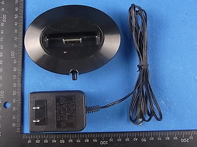
PMJTX1
Oct 17, 2011Audio Transmitter
Equipment Class
DSS - Part 15 Spread Spectrum Transmitter