PMJT4005.8 GHz Multi Channel Audio Transmitter
Amphony Corp.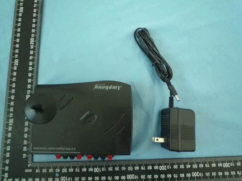
Click to zoom
Application Details
- Equipment Class
- DXX - Part 15 Low Power Communication Device Transmitter
- Date of Grant
- Mar 16, 2011
- Application Purpose
- Original Equipment
- Date of Application
- Mar 16, 2011
- Equipment Note
- 5.8 GHz Multi Channel Audio Transmitter
- Frequency Range
- 5787.50000000 - 5787.50000000
- Company
- Amphony Corp.
- Country
- United States
Documents & Files
Document Text
Text extracted from the exhibit documents filed with the FCC. Open a document above to read the original.
Users Manual
R User and Installation Guide Multi Channel Audio Transmitter 5.8 GHz Model 400 05257595100 ContentsUnpackingConnecting the transmitterPlacing the transmitterOperating the transmitterTroubleshootingTechnical specificationsSafety informationLimited Warranty ................................................................................. 3 ........................................................ 3 ............................................................... 6 ........................................................... 6 ......................................................................... 7 ............................................................. 9 ................................................................... 10 ..................................................................... 12 LEGAL LIMITATIONSREPLACEMENT AS PROVIDED UNDER THIS WARRANTY IS YOUREXCLUSIVE REMEDY. WE SHALL NOT BE HELD LIABLE FOR ANYINCIDENTAL OR CONSEQUENTIAL DAMAGES FOR BREACH OF ANYEXPRESSED OR IMPLIED WARRANTY ON THIS EQUIPMENT, NOR FORANY INCIDENTAL OR CONSEQUENTIAL DAMAGES RESULTING FROMTHE USE OF, OR INABILITY TO USE, THIS EQUIPMENT. UNDER NOCIRCUMSTANCES SHALL OUR LIABILITY, IF ANY, EXCEED THEPURCHASE PRICE PAID FOR THIS EQUIPMENT, EXCEPT TO THEEXTENT PROHIBITED BY APPLICABLE LAW. EXCEPT AS PROVIDEDHEREIN, WE MAKE NO WARRANTIES, EXPRESS OR IMPLIED,INCLUDING WARRANTIES OF MERCHANTABILITY AND FITNESS FOR APARTICULAR PURPOSE. WE RESERVE THE RIGHT TO REFUSE TOHONOR THIS WARRANTY IF WE DETERMINE ANY OF THE ABOVEEXCEPTIONS TO HAVE CAUSED THIS EQUIPMENT NOT TO HAVEPERFORMED PROPERLY. THIS WARRANTY SHALL BE VOID IF ANYFACTORY-APPLIED IDENTIFICATION MARK, INCLUDING BUT NOTLIMITED TO SERIAL NUMBERS AND WARRANTY LABELS, HAS BEENALTERED OR REMOVED. THIS WARRANTY SHALL ALSO BE VOID IF THETRANSMITTER OR AMPLIFIER HAVE BEEN OPENED BY ANUNAUTHORIZED PERSON.This warranty gives you specific legal rights which may vary from state to state.Some states do not allow the exclusion or limitation of incidental orconsequential damages, or allow limitations on the duration of an impliedwarranty, so those limitations may not apply to you. No responsibility is assumed for the presence of interference outside of Amphony’s control, such as other transmitters or cordless phones, which mayhamper proper signal reception.Note:User and Installation Guide R 05257595100 Step 1 Connecting the transmitter The transmitter has two stereo audio inputs, one zone-A and one zone-B input.4 audio channels can be transmitted simultaneously. Both zone-A and zone-B audioinputs can connect either to an unbalanced line-level audio output or a balancedamplified speaker output. For best audio quality, we recommend using theunbalanced line-level audio input.The transmitter can transmit to Model 400 wireless audio receivers and Model 480wireless amplifiers. Each audio channel is encoded with a channel ID and can beselected by each wireless receiver. Regardless of whether any specific audio channel is transmitted to a wireless receiver or wireless amplifier, both the transmitter line-level and amplified speakeraudio inputs can be used to feed audio into the transmitter.Connect the transmitter to an unbalanced audio input by using the supplied phone-RCA audio cable. Connect the phone jack with the line level input of the transmitterand the RCA jack with the RCA output of your audio source.Alternatively, connect the transmitter to an amplified speaker output by using thesupplied speaker cables. Be sure to observe the correct polarity of the speakercable.Note: If one of the speaker cables is switched (reversed), one speaker will receive an opposite polarity signal which will degrade sound performance.It is possible to connect zone-A audio inputs to line-level audio outputs and zone-Baudio inputs to amplified speaker outputs and vice versa. However, only theunbalanced line level input or speaker inputs of each zone can be used, i.e. youcannot mix audio inputs within a zone.Connect the supplied small AC adapter’s barrel-shaped plug into the DC 9V jack,and then plug the transformer into a standard AC outlet. We recommend the use ofa surge protector to protect the transmitter from power surges. Unpacking: Check that this package contains: One 5.8 GHz Digital Audio transmitter - Model 400, one 9 V AC adapter (wallwart),four short speaker cables, two RCA audio cables. ATTENTION! Do not connect both the line level audio input and amplified speakeraudio input of the same zone. This may damage your audio source. User and Installation Guide R User and Installation Guide R Limited warrantyWHAT YOUR WARRANTY COVERSThis warranty extends only to the original user of the equipment (“you”, ”your”)and is limited to the purchase price of each part. Amphony and its affiliatedcompanies (”we”, ”our”, ”us”) warrant this Multi Channel Audio Transmitteragainst defects in materials or workmanship as follows. For a period of ninety (90) days from the original date of purchase, if we determine that the equipment is defective subject to the limitations of thiswarranty, we will replace it at no charge for labor. We warrant any such workdone against defects in materials or workmanship for the remaining portion ofthe original warranty period. For a period of one (1) year from the original date of purchase, we will supply, at no charge, new or rebuilt replacement parts in exchange for parts wedetermine are defective subject to the limitations of this warranty. We warrantany such replacement parts against defects in materials or workmanship forthe remaining portion of the original warranty period. ”Parts” means items included in this package. It does include other parts purchased separately.LABOR:PARTS:Note: not WHAT YOUR WARRANTY DOES NOT COVERThis warranty consumer instruction, physical setup or adjustment of any consumer electronic equipment, or signal transmissionproblems.This warranty cosmetic damage, damage due to the affixing of any attachment not provided with the product, loss…
Text truncated - open the document above for the full version.
Block Diagram
Amphony Corp. 3/9/2011 Federal Communications Commission Equipment Authorization Branch 7435 Oakland Mills Road Columbia, MD 21046 Request for Confidentiality Company name: Amphony Corp. FCC ID: PMJT400 FCC Part 15_C Certification Gentlemen, In accordance with 0.459 of CFR 47, Amphony Corp. hereby requests confidentiality of the following documents for the subject application: • Operational Description • Block Diagrams • Schematics Diagrams • These documents contain detailed system and equipment description and related information about the product which Amphony Corp. considers to be proprietary, confidential and a custom design and otherwise would not release to the general public. Since the design is a basis from which future technological products will evolve, Amphony Corp. considers that this information would be of benefit to its competitors and that the disclosure of the information in these documents would give competitors an unfair advantage in the market. Sincerely, Signature Name: Kurrat Title: President Company address 1: 1006 S. Raven Rd., Shorewood, Illinois 60404, United States
Cover Letter(s)
Amphony Corp. Letter of Authorization Company: Amphony Corp. Address: 1006 S. Raven Rd., Shorewood, Illinois 60404, United States. Product Name: 5.8 GHz Multi Channel Audio Transmitter Model Number: Model 400 We authorize MiCOM Labs, 440 Boulder Court, Suite 200, Pleasanton, CA 94566, USA, to act on our behalf on all matters concerning the above named equipment. This shall include the following: - Approval applications and procedures - Payment of approval fees We declare that MiCOM Labs, 440 Boulder Court, Suite 200, Pleasanton, CA 94566, USA, is allowed to forward all information related to the approval project to the applied notified body and to the notification entities and to discuss any issues concerning the approval application. Any and all acts carried out by MiCOM Labs on our behalf shall have the same effect as acts of our own. Name: Jens Kurrat Date: 03.07.2011 Title: President Signature of applicant
Cover Letter(s)
Amphony Corp. Date: 2011-3-09 MiCOM Labs Inc. 440 Boulder Court, Suite 200, Pleasanton, CA 94566, USA Authority to Act as an Agent We authorize Advance Testing Service Co., Ltd. and BZT - TCP Certification GmbH, to act on our behalf on all matters concerning the application and documents submitted to MiCOM Labs Inc. for product certification. In case of FCC, we certify that we are not subject to a denial of Federal benefits, that include FCC benefits, pursuant to Section 5301 of the Anti- Drug Abuse Act of 1988, 21 U.S.C. §862 because of a conviction for possession or distribution of a controlled substance. Agency Agreement expiration date: 6 months 12 months By: Jens Kurrat Title: President On behalf of: Amphony Corp. Telephone: (815)729-1291 Signature of applicant:
Cover Letter(s)
The items indicated above must be submitted before processing can continue on the above referenced application. Failure to provide the requested information may result in application termination. Except as described in §0.459, correspondence and responses should be considered part of the permanent submission and may be viewed from the Internet after a Grant of Equipment Authorization is issued unless a request for confidentiality per Section 0.457 has been made for that particular exhibit. Please note that partial responses increase processing time and should not be submitted. Any questions about the content of this correspondence should be directed to the sender. March 17, 2011 RE: TCB Review of FCC ID: PMJT400 FCC ID: PMJT400 (MC # BZTX02) After an initial review of the submitted information, I have a few comments on the above referenced application. Depending on your responses, kindly understand there may be additional comments. Additionally, if some of the issues / concerns below are not clear, please do not hesitate to email me for clarification. 1) No fundamental emissions provided in test report. Limit is 50 millivolts per meter. Fundamental field strength or power must be provided. Revised test report provided. Fundamental emissions = 101.3 dBuV/m Vertical Polarity; Radiated 2) No FCC test site information included in test report. Test site must be FCC listed. 731 form indicates AIT as the test lab. Test report indicates ATS, with no other test site information provided. Test site location is required to be in the test report. Test report logo and format does not match other AIT test reports located in FCC database. Revised test report provided. Asia Institute Technology (Dongguan) Limited Add. : No.6 Binhe Road, Tianxin Village, Huangjiang, Dongguan, Guangdong, China. FCC Registered No.: 248337 3) Please note that the limits listed in the test report are incorrect for the fundamental emission. this is believed to be in error. The limits listed in the report are below. Emission of the fundamental should be 50 millivolts/m, not microvolts per meter. Revised test report provided. z Page 2 March 17, 2011 4) Dates of tests are not consistent throughout report. Page 20 indicates testing performed in 2010. Typographical error in report. Not an issue for FCC. Best regards, Clinton Bradley Technical Reviewer Mail to: [email protected]
External Photos
Page 27 of 29 Report No.: ATS-2011NT0309023E 6 . APPENDIX-Photographs of EUT Constructional Details
ID Label/Location Info
Product name: 5.8 GHz Multi Channel Audio Transmitter Model : Model 400 FCC ID: PMJT400 This device complies with Part 15 of the FCC Rules. Operation is subject to the following two conditions: (1) this device may not cause harmful interference, and (2) this device must accept any interference received, including interference that may cause undesired o peration.
Internal Photos
Page 28 of 29 Report No.: ATS-2011NT0309023E Page 29 of 29 Report No.: ATS-2011NT0309023E
Test Report
Page 1 of 29 Report No.: ATS-2011NT0309023E FCC RADIO TEST REPORT Report Reference No. ............... : ATS-2011NT0309023E Compiled by (+ signature) ........... Jim He Approved by (+ signature) ........... Bovey Yang Date of issue ............................... : 2011-03-06 Applicant’s name ........................... : Amphony Corp. Address ...................................... : 1006 S. Raven Rd., Shorewood, Illinois 60404, United States Manufacture's Name ...................... : Amphony Corp. Address ...................................... : 1006 S. Raven Rd., Shorewood, Illinois 60404, United States. Test specification: Standard ..................................... : FCC Part15.249 Test procedure ............................... : ANSI C63.4-2009 Test item description Product name ........................ : 5.8 GHz Multi Channel Audio Transmitter FCC ID Trademark ............................ : Amphony Model and/or type reference : Model 400 Rating(s) ................................ : DC 9V From Adapter AC 120V/60Hz Testing .................................................... : Date of receipt of test item ...................... : 0 1 Mar. 2011 Date (s) of performance of tests ............. : 01 Mar. 2011 ~05 Mar. 2011 Date of Issue ........................................... : 06 Mar. 2011 Test Result ............................................... : Pass Page 2 of 29 Report No.: ATS-2011NT0309023E Table of Contents Page 1 . SUMMARY OF TEST RESULTS 3 2 . GENERAL INFORMATION 5 2.1 GENERAL DESCRIPTION OF EUT 5 2.2 DESCRIPTION OF TEST MODES 7 2.3 BLOCK DIGRAM SHOWING THE CONFIGURATION OF SYSTEM TESTED 8 2.4 DESCRIPTION OF SUPPORT UNITS(CONDUCTED MODE) 9 3 . TEST RESULT 11 3.1 ANTENNA REQUIREMENT 11 3.1.1 STANDARD REQUIREMENT 11 3.1.2 EUT ANTENNA 11 3.2 COND UCTED EMISSION MEASUREMENT 12 3.2.1 POWER LINE CONDUCTED EMISSION LIMITS 12 3.2.2 TEST PROCEDURE 13 3.2.3 DEVIATION FROM TEST STANDARD 13 3.2.4 TEST SETUP 13 3.2.5 TEST RESULT 14 3.3 RADIATED EMISSION MEASUREMENT 16 3.3.1 RADIATED EMISSION LIMITS 16 3.3.2 TEST PROCEDURE 17 3.3.3 DEVIATION FROM TEST STANDARD 17 3.3.4 TEST SETUP 18 3.3.1 TEST RESULTS (BLOW 30MHZ) 19 3.3.1.1 TEST RESULTS (BETWEEN 30 – 1000 MHZ) 19 3.3.1.2 TEST RESULTS (ABOVE 1000 MHZ) 21 4 . BANDWIDTH TEST 23 4.1 TEST PROCEDURE 23 4.2 DEVIATION FROM STANDARD 23 4.3 TEST SETUP 23 4.4 TEST RESULTS 24 5 . EUT TEST PHOTO 25 6 . APPENDIX-Photographs of EUT Constructional Details Page 3 of 29 Report No.: ATS-2011NT0309023E 1. SUMMARY OF TEST RESULTS Test procedures according to the technical standards: FCC Part15, Subpart C (15.249) Standard Section Test Item Judgment Remark 15.207 Conducted Emission Pass 15.203 Antenna Requirement Pass 15.249 Radiated Spurious Emission Pass 15.249 Occupied Bandwidth Pass NOTE: (1) ” N/A” denotes test is not applicable in this Test Report. Page 4 of 29 Report No.: ATS-2011NT0309023E 1.1 TEST FACILITY Asia Institute Technology (Dongguan) Limited Add. : No.6 Binhe Road, Tianxin Village, Huangjiang, Dongguan, Guangdong, China. FCC Registered No.: 248337 1.2 MEASUREMENT UNCERTAINTY The reported uncertainty of measurement y ± U,where expended uncertainty U is based on a standard uncertainty multiplied by a coverage factor of k=2,providing a level of confidence of approximately 95 %。 No. Item Uncertainty 1 Conducted Emission Test ±1.38dB 2 Radiated Emission Test ±3.17dB 3 RF power,conducted ±0.16dB 4 Spurious emissions,conducted ±0.21dB 5 All emissions,radiated(<1G) ±4.68dB 6 All emissions,radiated(>1G) ±4.89dB Page 5 of 29 Report No.: ATS-2011NT0309023E 2. GENERAL INFORMATION 2.1 GENERAL DESCRIPTION OF EUT Equipment 5.8 GHz Multi Channel Audio Transmitter Trade Name Amphony Model Name Model 400 OEM Brand/Model Name N/A Model Difference N/A Product Description The EUT is a 5.8 GHz Multi Channel Audio Transmitte r Operation Frequency: 5.7875 GHz Modulation Type: ASK Antenna Designation: Integrated omnidirectional Antenna Gain(Peak) 3 dBi Channel List Please refer to the Note 2. Power Source DC Voltage supplied from Adapter AC 120V/60Hz Power Rating DC 9V From Adapter AC 120V/60Hz Connecting I/O Port(s) Please refer to the User's Manual Products Covered N/A EUT Modification(s) N/A Note: 1. For a more detailed features description, please refer to the manufacturer’s specifications or the User's Manual. Page 6 of 29 Report No.: ATS-2011NT0309023E 2. Channel List Channel Frequency (MHz) Channel Frequency (MHz) Channel Frequency (MHz) Channel Frequency (MHz) 01 5787.5 3. Table for Filed Antenna Ant . Brand Model Name Antenna Type Connector Gain (dBi) NOTE 1 N/A N/A Integrated omnidirectional NA 3 Antenna Page 7 of 29 Report No.: ATS-2011NT0309023E 2.2 DESCRIPTION OF TEST MODES To investigate the maximum EMI emission characteristics generates from EUT, the test system was pre-scanning tested base on the consideration of following EUT operation mode or test configuration mode which possible have effect on EMI emission level. Each of these EUT operation mode(s) or test configuration mode(s) mentioned above was evaluated respectively. Pretest Mode Description Mode 1 CH1 For Conducted Emission Final Test Mode Description Mode 1 CH1 For Radiated Emission Final Test Mode Description Mode 1 CH1 Page 8 of 29 Report No.: ATS-2011NT0309023E 2.3 BLOCK DIGRAM SHOWING THE CONFIGURATION OF SYSTEM TESTED E-1 EUT E-2 RX E-3 Adapter C-1 Page 9 of 29 Report No.: ATS-2011NT0309023E 2.4 DESCRIPTION OF SUPPORT UNITS(CONDUCTED MODE) The EUT has been tested as an independent unit together with other necessary accessories or support units. The following support units or accessories were used to form a representative test configuration during the tests. Item Equipment Mfr/Brand Model/Type No. FCC ID Series No. Note E-1 5.8 GHz Multi Channel Audio Transmitte r Amphony Model 400 N/A N/A EUT E-2 RX Amphony Model 400 N/A N/A N/A E-3 Adapter N/A LK-DC 090025 N/A N/A N/A Item Shielded Type Ferrite Core Length Note C-1 YES NO 120 N/A Note: (1) The support equipment was authorized by…
Text truncated - open the document above for the full version.
Test Setup Photos
Page 25 of 29 Report No.: ATS-2011NT0309023E 5. EUT TEST PHOTO Conducted Measurement Photos Page 26 of 29 Report No.: ATS-2011NT0309023E Radiated Measurement Photos
Contact Information
Applicant
Jeff Barrett
Technical Contact
Amphony Corp.Jim
[email protected](815)729-1288
1006 S. Raven Rd. · Shorewood, Illinois · United States
Non-Technical Contact
Amphony Corp.Jens Kurrat
[email protected](815)729-1291
Test Firm
Dongguan Yaxu (AiT) Technology LimitedJackie Deng
Technical Specifications
| # | Rule Parts | Frequency Range | Power Output |
|---|---|---|---|
| 1 | 15C | 5.79 GHz - 5.79 GHz | 500.00 µW |
Other Applications from Amphony Corp.
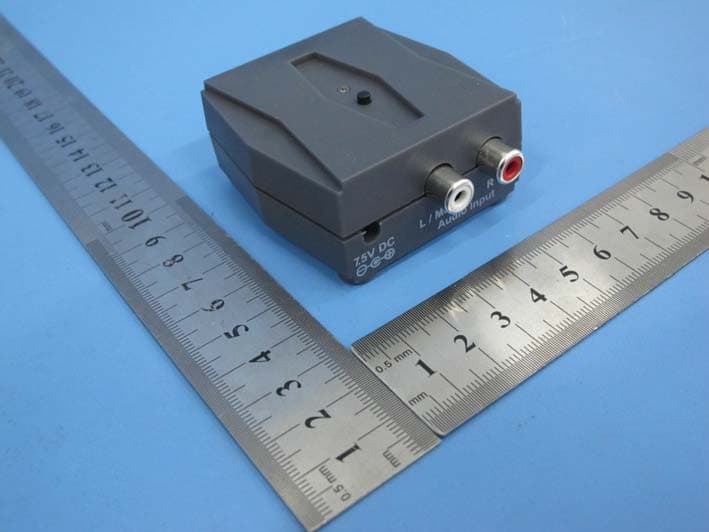
PMJTX2
Jan 19, 2015Audio transmitter
Equipment Class
DSS - Part 15 Spread Spectrum Transmitter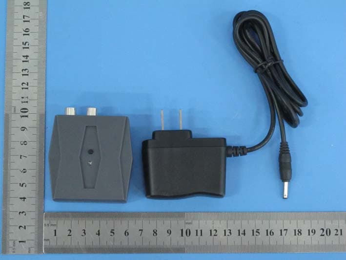
PMJRX2
Jan 19, 2015Audio Receiver
Equipment Class
DSS - Part 15 Spread Spectrum Transmitter
PMJB300
Mar 03, 2014BlueFidelity Bluetooth Amplifier
Equipment Class
DSS - Part 15 Spread Spectrum Transmitter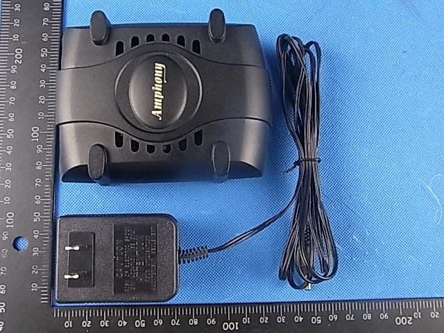
PMJRX1
Oct 17, 2011Audio Receiver
Equipment Class
DSS - Part 15 Spread Spectrum Transmitter
PMJTX1
Oct 17, 2011Audio Transmitter
Equipment Class
DSS - Part 15 Spread Spectrum Transmitter