PMTSG24GUSB RF Remote Controller
Soundgraph, Inc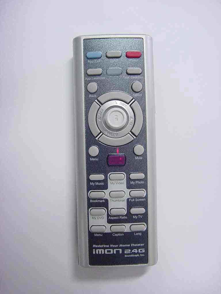
Click to zoom
Application Details
- Equipment Class
- DXX - Part 15 Low Power Communication Device Transmitter
- Date of Grant
- Nov 03, 2005
- Application Purpose
- Original Equipment
- Date of Application
- Nov 03, 2005
- Equipment Note
- USB RF Remote Controller
- Frequency Range
- 2430.00000000 - 2460.00000000
- Company
- Soundgraph, Inc
- Country
- South Korea
Documents & Files
Document Text
Text extracted from the exhibit documents filed with the FCC. Open a document above to read the original.
Users Manual
iMON & Multi-Median Users Guide (Draft) z SoundGraph, Inc. -2- Table of Contents In your Package 4 1. iMON 2.4G LT 4 2. iMON 2.4G DT 4 S/W, H/W Installation and Remote Controller 5 1. Installation Process 5 1) S/W Installation 5 2) H/W (RF Receiver) Installation 5 3) Execute iMON Manager 7 2. Button Layout and its Feature of iMON Remote Controller 8 1) iMON 2.4G Remote Controller 8 Multi-Median Users Guide 18 1. Screen Layout of ‘Multi-Median’ 18 1) Main View 18 2) Hard Disk Drive 19 3) Media Folder View 20 4) Media File View 20 5) Media Preview 21 6) Full Screen View 22 7) DVD View 22 8) TV View 22 9) Digital Camcoder View 22 2. Using Remote Controller on Multi-Median 23 3. Using Mouse on Multi-Median 25 4. Setting Environment 26 1) Back 26 2) Scan Media 26 3) Music 26 4) Movie 26 5) Photo 27 6) TV 27 7) DVD 27 8) Digital Camcoder 27 5. Installation of Video Codec 27 -3- iMON Users Guide 29 1. Using Application Launcher 29 2. Using Task Switcher 29 3. Application Control 30 4. Using All Time Control Mode 30 5. Using Monitor Resolution Changer 31 6. Using Timer 31 7. Using Virtual Kyboard 32 8. Register New Remote Controller 33 9. Setting Program Command 33 10. Setting Windows Command 34 11. Setting Customized Windows Command 34 12. Setting Macro 35 13. Setting Option 35 Update of iMON & Multi-Median 37 SoundGraph, Inc. 38 -4- This device complies with Part15 of the FCC Rules. Operation is subject to the following two conditions: (1) this device may not cause harmful interference, and (2) this device must accept any interference received, including interference that may cause undesired operations. INFORMATION TO THE USER This equipment has been tested and found to comply with the limits for a Class B digital device, pursuant to part 15 of the FCC Rules. These limits are designed to provide reasonable protection against harmful interference in a residential installation. This equipment generates, uses and can radiate radio frequency energy and, if not installed and used in accordance with the instructions, may cause harmful interference to radio communications. However, there is no guarantee that interference will not occur in a particular installation. If this equipment does cause harmful interference to radio or television reception, which can be determined by turning the equipment off and on, the user is encouraged to try to correct the interference by one more of the following measures: -Reorient or relocate the receiving antenna. -Increase the separation between the equipment and receiver -Correct the equipment into an outlet on a circuit different from that to which The receiver is connected. -Consult the dealer or an experienced radio/TV technician for help. WARNING (Part 15.21) Changes or modifications not expressly approved by the manufacturer could void the user’s authority to operate the equipment. “Note: The manufacturer is not responsible for any Radio or TV interference caused by unauthorized modifications to this equipment. Such modifications could void the user’s authority to operate the equipment.” -5- In your Package iMON product lineup is divided into four different models according to the RF remote controller and RF receiver. Each product is composed as like follows. Please check the components on the below in your box. 1. iMON 2.4G LT In the Box : 1 iMON 2.4G Remote Controller, 1 iMON 2.4G LT (External RF Receiver), 1 Installation CD (iMON Manager, Multi-Median), 2 AAA Batteries, 1 Users Guide Specification of Remote controller Operation range : 30m Battery : 1.5V AAA type Specification of External Receiver OS : Windows 98, 98 Se, Me Windows 2000, Windows XP System Recommendation : Pentium III or higher, 256 Mb of higher USB 1.1 compatibility z 2. iMON 2.4G DT In the Box : 1 iMON 2.4G Remote Controller, 1 iMON 2.4G DT (Internal RF Receiver), 1 Installation CD (iMON Manager, Multi-Median), 2 AAA Batteries, 1 low profile bracket, 1 usb -6- cable, 1 Users Guide Specification of Remote controller Operation range : 30m Battery : 1.5V AAA type Specification of Ixternal Receiver OS : Windows 98, 98 Se, Me Windows 2000, Windows XP System Recommendation : Pentium III or higher, 256 Mb of higher Mounted on PCI port USB 1.1 compatibility z S/W, H/W Installation and Remote Controller Please read this users guide before the installation of your iMON Station (IR Receiver). 1. Installation Process 1) S/W Installation -7- Insert iMON&Multi-Median Installation CD to your CD ROM, and install the iMON Manager and Multi-Median according to the auto running S/W installation process. 2) H/W (RF Receiver) Installation External iMON 2.4G LT Installation Connect your External iMON Station to your USB port, then assign the H/W driver according to the ‘Found New H/W Wizard’. Assign the CD ROM drive for searching H/W driver. Internal iMON 2.4G DT Installation Internal iMON 2.4G DT can be loaded to the 3.5” floppy drive bay. The additional feature of internal type iMON 2.4G DT is that you could power on your PC system using the power button of the remote controller. After turn off your PC system, open your PC case and connect the cable to its proper pin refer to the following picture. -8- Internal iMON 2,4G DT is connected to mainboard with two cables, PC case with one cable, Power Supply with one another cable. You should be careful to connect these four cables refer to your mainboard manual. The connectors that each cable needs to be connected are as like follows. -9- 1. Stand-By Power Connection Cable A1 : (2pin, iMON Inside ‘ST PWR1’ connector) A2 : (2pin, Mainboard power extension cable) 2. Mainboard Power Switch Connection Cable B1 : (2pin, iMON Inside ‘M/B PWR’ connector) B2 : (2pin, Mainboard power switch connector) 3. PC Case Power Switch Connection Cable C1 : (2pin, iMON Inside ‘PWR S/W’ connector) C2 : (2pin, PC Case power switch connector) 4. Mainboard USB Connection Cable D1 : (5pin, iMON Inside USB connector) D2 : (4pin, Mainboard USB internal connector) The names of the additional …
Text truncated - open the document above for the full version.
Cover Letter(s)
ONETECH Corp. http://www.onetech.co.kr 505 SK APT Factory, 223-28 Sangdaewon 1-Dong, Jungwon-Gu, Seongnam-City, Kyunggi-Do 462-121, Korea [ Tel ] 82-31-746-8500, [ Fax ] 82-31-746-8700 ONETECH November 4, 2005 FCC Laboratory 7435 Oakland Mills Road Columbia, MD 21046 Attention: Application Examiner Reviewing Engineer Re: Request for confidentiality per Section 0.459 of FCC Rules Applicant: SoundGraph, Inc. FCC ID: PMTSG24G To whom it may concern, Request is hereby submitted, on behalf of my client, Bluebird Soft Inc., to withhold from public review certain portions of the application for equipment certification for the referenced FCC identifier. In particular, the following sections of the application and report are requested to be kept confidential: Schematics Rationale for request for confidentiality: Bluebird Soft Inc. has invested considerable time and materials in research and development to produce the referenced product. Disclosure of the confidential portions of this application to competitors would give them competitive advantage in developing similar products. If you have questions or need further information, please contact the undersigned. Sincerely, Y.K. Kwon / Director Onetech Corp. Email: [email protected]
External Photos
FCC ID.: PMTSG24G File No. : Error! Unknown document property name. ONETECH Testing & Evaluation Lab. FCC ID.: PMTSG24G File No. : Error! Unknown document property name. ONETECH Testing & Evaluation Lab.
ID Label/Location Info
FCC ID.: PMTSG24G File No.: E05OR-078 ONETECH Testing & Evaluation Lab. IDENTIFICATION LABEL: PROPOSED FCC ID LABEL Due to the product size, only the FCC ID shall be permanently affixed to the rear side of the equipment and other information shall be placed in the instruction manual. This device complies with Part 15 of the FCC Rules. Operation is subject to the following two conditions: (1) this device may not cause harmful interference, and (2) this device must accept any interference received, including interference that may cause undesired operations. Made in Korea FCC ID : PMTSG24G FCC ID AREA
Internal Photos
FCC ID.: PMTSG24G File No. : E05OR-078 ONETECH Testing & Evaluation Lab. FCC ID.: PMTSG24G File No. : E05OR-078 ONETECH Testing & Evaluation Lab. FCC ID.: PMTSG24G File No. : E05OR-078 ONETECH Testing & Evaluation Lab.
Operational Description
PRODUCT SPECIFICATION nRF2402/nRF2402G Single Chip 2.4 GHz Radio Transmitter Nordic Semiconductor ASA - Vestre Rosten 81, N-7075 Tiller, Norway - Phone +4772898900 - Fax +4772898989 Revision: 2.0 Page 4 of 31 April 2005 ELECTRICAL SPECIFICATIONS Conditions: VDD = +3V, VSS = 0V, T A = - 40ºC to + 85ºC Symbol Parameter (condition) Notes Min. Typ. Max. Units Operating conditions VDD Supply voltage 1.9 3.0 3.6 V TEMP Operating Temperature -40 +27 +85 ºC Digital input pin V IH HIGH level input voltage 0.7·VDD VDD V V IL LOW level input voltage Vss 0.3·VDD V Digital output pin V OH HIGH level output voltage (I OH =-0.5mA) VDD- 0.3 VDD V V OL LOW level output voltage (I OL =0.5mA) Vss 0.3 V General RF conditions f OP Operating frequency 1) 2400 2527 MHz f XTAL Crystal frequency 2) 4 20 MHz ∆f Frequency deviation ±156 kHz R GFSK GFSK data rate ShockBurst™ >0 1000 kbps R GFSK GFSK data rate Direct Mode 3) 250 1000 kbps F CHANNEL Channel spacing 1 MHz Transmitter operation P RF Maximum Output Power 4) 0 +4 dBm P RFC RF Power Control Range 16 20 dB P RFCR RF Power Range Control Resolution ±3 dB P BW 20dB Bandwidth for Modulated Carrier 1000 kHz P RF2 2 nd Adjacent Channel Transmit Power 2MHz -20 dBc P RF3 3 rd Adjacent Channel Transmit Power 3MHz -40 dBc I VDD Supply current @ 0dBm output power 5) 11.5 mA I VDD Supply current @ -5dBm output power 5) 10.0 mA I VDD Supply current @ -10dBm output power 5) 8.5 mA I VDD Supply current @ -20dBm output power 5) 7.0 mA I VDD Average Supply current @ -5dBm output power, ShockBurst™ 6) 500 μA I VDD Supply current in stand-by mode 12 μA I VDD Supply current in power down 200 nA NOTES: 1) Usable band is determined by local regulations 2) The crystal frequency may be chosen from 5 different values (4, 8, 12, 16, and 20MHz) which are specified in the configuration word, see Table 8. 16MHz is required for 1Mbps operation. 3) Data rate must be either 250kbps or 1000kbps. 4) Antenna load impedance = 100Ω+j175Ω 5) Antenna load impedance = 100Ω+j175Ω. Effective data rate 250kbps or 1Mbps. 6) Antenna load impedance = 100Ω+j175Ω. Effective data rate 10kbps. Table 4 nRF2402/nRF2402G electrical specifications
Test Report
Page 1 of 15 FCC ID. : PMTSG24G File No. : E05OR-078 It should not be reproduced except in full, without the written approval of ONETECH. EMC-007(Rev.0) HEAD OFFICE : #505 SK APT. Factory 223-28, Sangdaewon 1 Dong, Jungwon-Gu, Seongnam-City, Kyunggi-Do, 462-121, Korea (TEL: 82-31-746-8500 FAX: 82-31-746-8700) EMC Testing Dept : 426-1 Daessangryung-Ri, Chowol-Myun, Kwangju-Kun, Kyunggi-Do 464-860 Korea. (TEL: 82-31-765-8289 FAX: 82-31-766-2904) ONETECH Testing & Evaluation Lab. ELECTROMAGNETIC EMISSION C OMPLIANCE REPORT FOR LOW-POWER, NON-LICENSED TRANSMITTER Test report file number : E05OR-078 Applicant : SoundGraph, Inc Address : 621-1 Yeoksam 1-dong, Gangnam-gu, Seoul Korea Manufacturer : SoundGraph, Inc. Address : 621-1 Yeoksam 1-dong, Ganhnam-gu, Seoul Korea Type of Equipment : USB RF Remote Controller FCC ID. : PMTSG24G Model Name : iMON 2.4G Serial number : None Total page of Report : 15 pages (including this page) Date of Incoming : October 17, 2005 Date of issue : October 28, 2005 SUMMARY The equipment complies with the regulation; FCC Part 15 Subpart C Section 15.249. This test report only contains the result of a single test of the sample supplied for the examination. It is not a generally valid assessment of the features of the respective products of the mass-production. Prepared by: Reviewed by: Young-Min, Choi / Senior Engineer Y. K. Kwon / Director EMC Div. EMC Div. ONETECH Corp. ONETECH Corp. Page 2 of 15 FCC ID. : PMTSG24G File No. : E05OR-078 It should not be reproduced except in full, without the written approval of ONETECH. EMC-007(Rev.0) HEAD OFFICE : #505 SK APT. Factory 223-28, Sangdaewon 1 Dong, Jungwon-Gu, Seongnam-City, Kyunggi-Do, 462-121, Korea (TEL: 82-31-746-8500 FAX: 82-31-746-8700) EMC Testing Dept : 426-1 Daessangryung-Ri, Chowol-Myun, Kwangju-Kun, Kyunggi-Do 464-860 Korea. (TEL: 82-31-765-8289 FAX: 82-31-766-2904) ONETECH Testing & Evaluation Lab. CONTENTS PAGE 1. VERIFICATION OF COMPLIANCE .............................................................................................4 2. TEST SUMMARY ..............................................................................................................................5 2.1 TEST ITEMS AND RESULTS..................................................................................................................................................5 2.2 ADDITIONS, DEVIATIONS, EXCLUSIONS FROM STANDARDS...............................................................................................5 2.3 RELATED SUBMITTAL(S) / GRANT(S)................................................................................................................................5 2.4 PURPOSE OF THE TEST.......................................................................................................................................................5 2.5 TEST METHODOLOGY........................................................................................................................................................5 2.6 TEST FACILITY...................................................................................................................................................................5 3. GENERAL INFORMATION ............................................................................................................6 3.1 PRODUCT DESCRIPTION.....................................................................................................................................................6 3.2 ALTERNATIVE TYPE(S)/MODEL(S); ALSO COVERED BY THIS TEST REPORT.....................................................................6 4. EUT MODIFICATIONS ....................................................................................................................6 5. SYSTEM TEST CONFIGURATION ...............................................................................................7 5.1 JUSTIFICATION...................................................................................................................................................................7 5.3 PERIPHERAL EQUIPMENT...................................................................................................................................................7 5.4 MODE OF OPERATION DURING THE TEST...........................................................................................................................7 5.5 CONFIGURATION OF TEST SYSTEM...................................................................................................................................8 5.6 ANTENNA REQUIREMENT..................................................................................................................................................8 6. PRELIMINARY TEST ......................................................................................................................8 6.1 AC POWER LINE CONDUCTED EMISSIONS TESTS.............................................................................................................8 6.2 GENERAL RADIATED EMISSIONS TESTS............................................................................................................................8 7. RADIATED EMISSION TEST, GENERAL REQUIREMENT....................................................9 7.1 OPERATING ENVIRONMENT...............................................................................................................................................9 7.2 TEST SET-UP.......................................................................................................................................................................9 7.3 MEASUREMENT UNCERTAINTY..........................................................................................................................................9 7.4 TEST EQUIPMENT USED.........................................................................................................................…
Text truncated - open the document above for the full version.
Test Setup Photos
FCC ID.: PMTSG24G File No. : E05OR-078 ONETECH Testing & Evaluation Lab. FCC ID.: PMTSG24G File No. : E05OR-078 ONETECH Testing & Evaluation Lab.
Contact Information
Applicant
Randy Ahn(General Manager)
Test Firm
ONETECH Corp.Gea-Won Lee
Technical Specifications
| # | Rule Parts | Frequency Range | Power Output |
|---|---|---|---|
| 1 | 15C | 2.43 GHz - 2.46 GHz | - |
Other Applications from Soundgraph, Inc
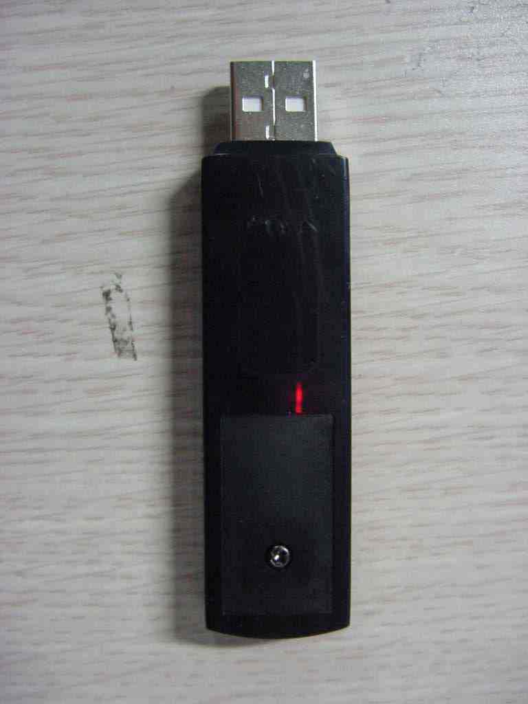
PMTSGLT
Nov 03, 2005USB RF Receiver
Equipment Class
JBP - Part 15 Class B Computing Device Peripheral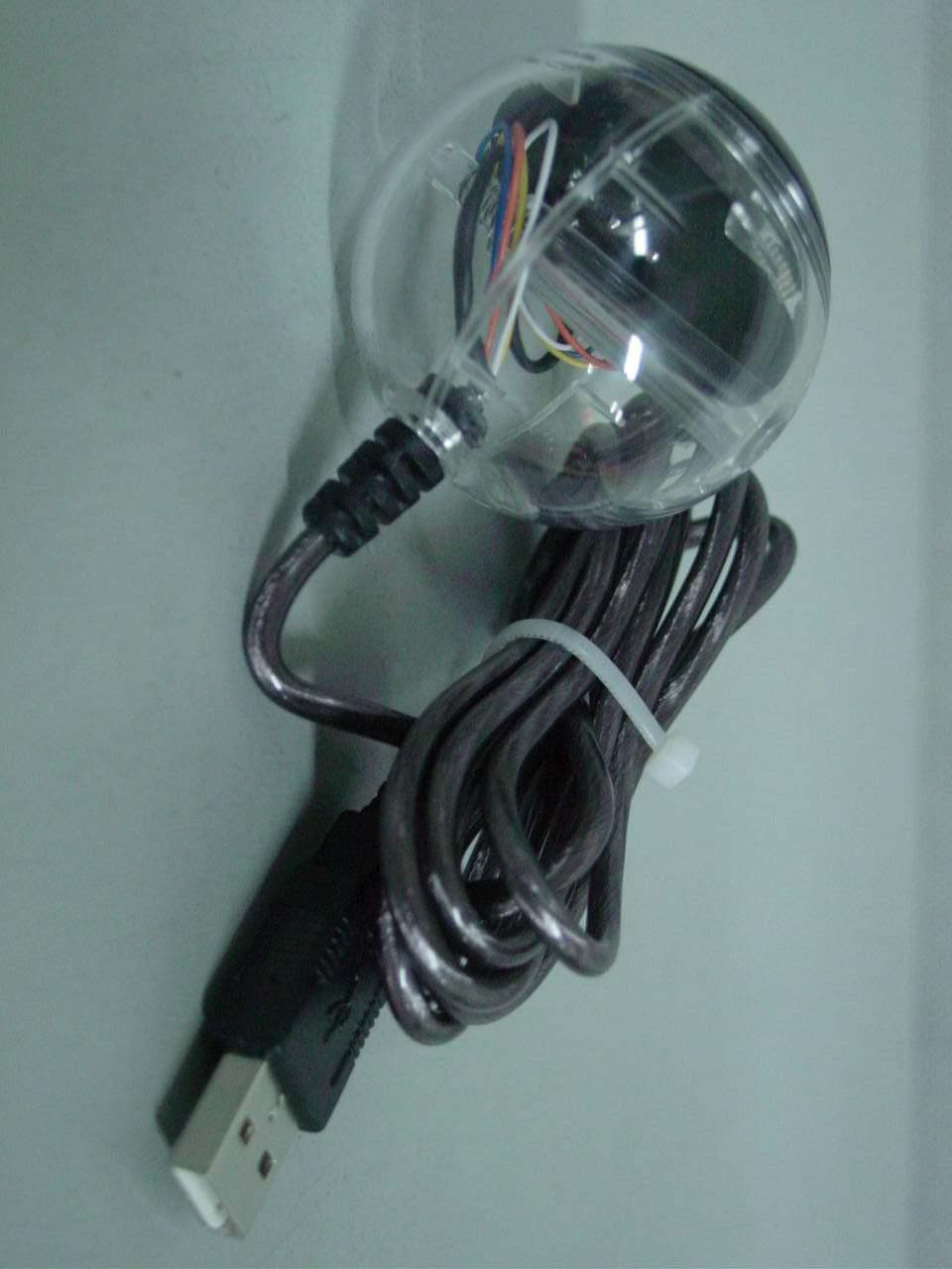
PMTSG03IMON
Feb 24, 2003Universal IR Remote Control Device
Equipment Class
JBP - Part 15 Class B Computing Device Peripheral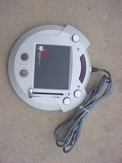
PMTSG01DJPAD2020
Jun 07, 2001USB Touch Pad as PC Accessory
Equipment Class
JBP - Part 15 Class B Computing Device Peripheral