PMYTRC497SkyWatch Traffic Advisory System
L-3 Communications, Avionics Systems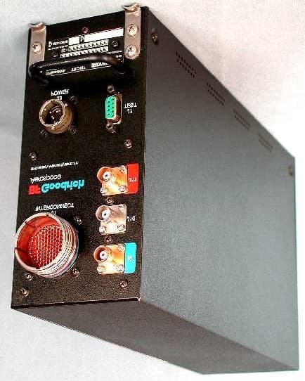
Click to zoom
Application Details
- Equipment Class
- TNB - Licensed Non-Broadcast Station Transmitter
- Date of Grant
- Feb 13, 2002
- Application Purpose
- Original Equipment
- Date of Application
- Jan 02, 2002
- Equipment Note
- SkyWatch Traffic Advisory System
- Frequency Range
- 1030.00000000 - 1030.00000000
- Country
- United States
Documents & Files
Document Text
Text extracted from the exhibit documents filed with the FCC. Open a document above to read the original.
Users Manual
Traffic Advisory System SKY497 Installation Manual This manual contains installation instructions and recommended flightline maintenance information for the SKY429 Traffic Advisory System. This information is supplemented and kept current by Change Notices and Service Bulletins published by BFGoodrich Avionics Systems. 009-10800-001 (Rev. C) BFGoodrich Avionics Systems, Inc.23 February 2001 5353 52 nd Street, S.E. Grand Rapids, MI USA 49512 A Rev. C ABOUT THIS MANUAL Chapter 1 – General Information This chapter includes equipment specifications and a functional description. It describes the various hardware configurations and includes a list of items furnished and items required but not supplied with the equipment. Chapter 2 - Installation This chapter contains instructions for unpacking the equipment and inspection for in-shipment damage. It also includes information required to locate, assemble and install the equipment. Chapter 3 – Installation Checkout This chapter contains instructions for doing post-installation and return to service checkout of the SKY497 using the BFGoodrich Avionics Systems TT391 Flightline Tester. Chapter 4 – Maintenance This chapter contains general flightline maintenance procedures. It includes periodic maintenance and troubleshooting; instructions for calibrating the directional antenna and instructions for the return of defective components. Appendix A – Signal and Cable Characteristics This appendix defines the electrical characteristics of all input and output signals. Appendix B – Installation Checkout Using The TCAS-201 Ramp Test Set This appendix contains instructions for doing post-installation and return to service checkout of the SKY497 using the IFR Systems TCAS-201 Ramp Test Set (with TCAS I firmware). Appendix C – Installation Checkout Using The TIC T-49C Flightline Tester This appendix contains instructions for doing post-installation and return to service checkout of the SKY497 using the TIC T-49C Flightline Tester. Appendix D – Using The Terminal Device This appendix contains instructions for using the Terminal Device for installation, testing or troubleshooting of the SKY497. Appendix E – Installation Checkout Using an Alternate Display This appendix contains instructions for doing post-installation and return to service checkout of the SKY497 using an Alternate Display. © Copyright 1997-2001 BFGoodrich Avionics Systems ____________________________ Trademarks Loctite® is a registered trademark of Loctite Corporation. Mylar ® and Teflon ® are registered trademarks of DuPont. Flamemaster ® is a registered trademark of Flamemaster Corporation. Rivnut® is a registered trademark of Rivnut Engineered Products, Inc. SKYWATCH ® and Stormscope® are registered trademarks of BFGoodrich Avionics Systems, Inc. SKY497 Installation Manual i Rev. C LIST OF EFFECTIVE PAGES Dates of original and changed pages are:Original (Rev. A)............................. 25 April 1997 Republished (Rev. B) ...........28 September 1998 Republished (Rev. C)..............23 February 2001 NOTE A vertical line in the outer margins of the page indicates the portion of the text affected by the change. Changes to illustrations (other than diagrams and schematics) are identified with a miniature pointing hand. Shading is used to highlight the area of diagrams and schematics containing a change. Total number of pages in this publication consists of the following: PageChange No.No. Title Page ................................................0 A Page ....................................................0 i thru viii ....................................................0 1-1 thru 1-16 ............................................0 2-1 thru 2-30 ............................................0 3-1 thru 3-8 .............................................0 PageChange No.No. 4-1 thru 4-20 ........................................ 0 A-1 thru A-10 ........................................ 0 B-1 thru B-6........................................... 0 C-1 thru C-4 .......................................... 0 D-1 thru D-6 ......................................... 0 E-1 thru E-6 .......................................... 0 INSERT LATEST CHANGED PAGES DESTROY SUPERSEDED PAGES. Those responsible for maintaining this publication should ensure that all previous changes have been received and incorporated. SKY497 Installation Manual ii Rev. C FOREWORD This manual provides information intended for use by persons who, pursuant to current regulatory requirements, are qualified to install this equipment. Because installations vary depending on a particular aircraft, this manual is intended as a guideline. Standard installation practices prescribed in FAA Advisory Circular No. 43.13 must be followed. If further information is required, contact: BFGoodrich Avionics Systems Attn: Field Service Engineering 5353 52nd Street, S.E. Grand Rapids, MI USA 49512 Tel. (800) 453-0288 or (616) 949-6600 We welcome your comments concerning this manual. Although every effort has been made to keep it free of errors, some may occur. When reporting a specific problem, please describe it briefly and include the manual part number, the paragraph/figure/table number, and the page number. Send your comments to: BFGoodrich Avionics Systems Attn: Technical Publications 5353 52nd Street, S.E. Grand Rapids, MI USA 49512 REVISION C HIGHLIGHTS Revision C is a republication. This republication completely replaces the exiting book. Materials for the alternate display and the configuration jumper’s have been added in addition to new and revised material of the SKY497. Discard previous editions of the old publication. This revision will be kept current by change notices, replace changed pages with the corresponding numbered page. A new list of effective pages will be issued with each change. The list shall reflect the current changes in addition to the tabulation of all previous changes, thus providing a complete history of the manual. SKY497 Install…
Text truncated - open the document above for the full version.
Users Manual
4. WHEN INTERFACING TO AN ALTERNATE DISPLAY THE SERVICE MENU CANNOT BE ACCESSED, THEREFORE A TERMINAL DEVICE (I.e., LAPTOP) MUST BE USED FOR SETUP AND CHECKOUTOF TRC497. 15. WHEN INTERFACING TO AN ALTERNATE DISPLAY THE SOFTKEY INPUTS MUST BE CONNECTED PER DISPLAY MANUFACTURER INSTRUCTIONS. SKY497 Installation Manual Figure 2-2. Interconnect Wiring Without WX-1000 (Sheet 1 of 2) 2-3 (page 2-4 blank) Rev. C HSYNCHIHSYNCLOVSYNCHIVSYNCLOVIDEOHIVIDEOLOPWRSWHIPWRSWLODSPGND-15+15SHIELD NOTES: 1. ALL WIRES TO BE 22 AWG EXCEPT WHERE NOTED. 2. TP - USE TWISTED SHIELDED PAIR CABLE. TERMINATE SHIELD TO AIRFRAME 5. A RADIO ALTIMETER, AIRDATA COMPUTER, OR OTHER ARINC 429 OUTPUT DEVICE MAY REPLACE ANALOG SENSORS FOR MAGNETIC HEADING, RADIOALTITUDE, OR BAROMETRIC ALTITUDE. SQUAT SWITCHLANDING GEAR POSITION ALTITUDE A1A2A4B1B2B4C1C2C4D4 2 2016151711242519131412182322 78 10 956 P101 J101 SEE NOTE #6 SEE NOTE #15 SEE NOTE #6 LOWHIGHZ Y X } } 26 VAC REFERENCE HEADING DIRECTIONAL GYRO COMPASS TRANSMITTER RECEIVER COMPUTER UNIT HDG_FLG+ HDG_FLG- SYNC_XSYNC_Y SYNC_Z SYNC_HI SYNC_LO 52536665645554 J1 P1 100 DPWR+15_OUT DPWR-15_OUT 7 DSPLY_GND 6 HSYNC_OUT_HI 14 HSYNC_OUT_LO 49 VSYNC_OUT_HI 48 VSYNC_OUT_LO 63 VIDEO_OUT_HI 62 VIDEO_OUT_LO 38 PWR_SW_HI 37 PWR_SW_LO 11 TOP_BOT 3 NY164_NY156 99 FIX_ROTOR 98 DR_RX+ 9 DR_RX- 8 DR_TX+ 2 DR_TX- 1 ALT_A1 40 ALT_A2 41 ALT_A4 50 ALT_B1 51 ALT_B2 56 ALT_B4 57 ALT_C1 58 ALT_C2 59 ALT_C4 71 ALT_D4 72 SQUAT 88 GEAR 87103993 SEE TABLE "A" TPTPTPTPTPTP TP ALT_COMMON TRC497 WX-1000 3. THE SUM CABLE WILL HAVE A BLUE BAND AT EACH END. THE DIFFERENCE CABLE WILL HAVE A RED BAND AT EACH END. 6. TIE THE OUTER SHIELD TO THE CONNECTOR BACKSHELL. CONNECTOR BACKSHELL IS CHASSIS GROUND.7. FOR FUTURE EXPANSION. LEAVE UNCONNECTED. HEADING INPUT CABLE DISPLAY CABLE SEE NOTE #6 8. DELETED WHT ORN BLU WHT BLU WHT BLU BLU WHT BLU WHT BLU WHT BLU WHT BLU ORN WHT BLUORNREDGRN WHT BLU WHT BLU WHT BLU WHT BLUBLU ORN WHT BLU WHT BLU ORN WHT BLU ORN RED GRN WHT BLU WHT WHT SEE NOTE #12 BLU WHT ORN ORN TP BLU WHT SEE NOTE #6 SFTKEY1SFTKEY2SFTKEY4SFTKEY3N/C+15V-15V SPARE_1SPARE_2SPARE_3 GROUND AT SENSOR (OR POWER SOURCE). 9. USE AUDIO_H FOR 600 OHM AUDIO SYSTEMS. USE AUDIO_L FOR 150 OHM AUDIO 10. DO NOT INSTALL EXTERNAL ISOLATION DIODES. SEE NOTE 10 SEE NOTE 10 SEE NOTE 10 DISPLAY STP_CONFIG4STP_CONFIG5STP_CONFIG6 959697 STP_CONFIG8STP_CONFIG7 8694 ALT_COMN 81 SFTKEY4_IN 82 SFTKEY3_IN 83 SFTKEY2_IN 84 SFTKEY1_IN 85 6867 HEADING_FLG DR_ALT422 777069 STEPPER_IN SYNCHRO_IN ALT_DISP4 SEE NOTE #7 78 ALT_DISP3 79 ALT_DISP2ALT_DISP1 80 BLKYEL BLU WHT BLU WHT WHT BLU WHT BLU YELBLK TPTP 43 21 CHASSISGND 1 SYSTEMS. 11. SPARE PINS 16, 17, 18, 19, 20, 25, 26, 27, 28, 29, AND 30 ARE NOT SHOWN AND NOT USED. HEADING VALID 12. HEADING FLAG CONNECTIONS NEED TO BE CONFIGURED PROPERLY FOR YOUR AIRCRAFT. DIGITIZER P/O P/O WHT BLU TP ORN ORN WHT BLU BLU WHT WHT ORN BLU WHT BLU BLU WHT BLU WHT BLU ORN WHT GROUND AIRFRAME TP 54556465665352 SYNC_LO SYNC_HI SYNC_Z SYNC_YSYNC_X HDG_FLG- HDG_FLG+ KI-525 INDICATOR J V SEE NOTE #6 H A FLAG- FLAG+ NCNC P1P2 TOPBOT STEPPERHEADINGALTERNATEINPUT SEE NOTE #13 HDG FLAG + UNREG +15 DRIVE MOTOR 1DRIVE MOTOR 3 HDG FLAG - 13. STEPPER HEADING INPUT MAY BE USED IN PLACE OF SYNCHRO HEADING.14. DELETED 1312 CONFIG_GNDCONFIG_GND SEE NOTE #6 VIDEO_IN_LO 35 SW_RET CWS_SS SFTKEY4_OUTSFTKEY3_OUTSFTKEY2_OUTSFTKEY1_OUT 4 3173747576 DPWR+15_IN DPWR-15_IN DSPLY_GND HSYNC_IN_HI HSYNC_IN_LO VSYNC_IN_HI VSYNC_IN_LO VIDEO_IN_HI 466036611547245 N/C N/CN/CN/CN/CN/CN/CN/CN/C GNDGNDGNDGND SEE NOTE #12 SKY497 Installation Manual Figure 2-2. Interconnect Wiring Without WX-1000 (Sheet 2 of 2) 2-5 (page 2-6 blank) Rev. C F3 J11 J7 TYPE TNC DIAG_GND DIAG_RX DIAG_TX 523 } TRANSMITTER RECEIVER COMPUTER UNIT J8 P8 +28V SPARE +28V_RET AIRCRAFT POWER ABC 16 AWG CONNECTOR TRC497 J10 DIFFERENCE J9 SUM CONNECTOR TYPE TNC CONNECTOR TYPE BNC TEST ONLY SUM DIFFERENCE BLUE BAND RED BAND DIRECTIONAL ANTENNA SEE NOTE # 3 TNC BNC TNC P9 P10P11 P1P2P3 AIRCRAFT POWER RETURN SEE NOTE #2 BIT_PROBE BIT_PROBE SEE NOTE #3 16 AWG (11 - 34VDC) NY164/NY156 TEST ONLY } 232221 IOP_SERIAL_TX IOP_SERIAL_GND IOP_SERIAL_RX NOTE: FOR 14V USE 7.5 A FOR 28V USE 5.0 A SUPPRESSION I/OAUDIO COMMON SEE NOTE #6 AUDIO HIGH SEE NOTE #2 SEE NOTE #6 TPTPTP 3233344243444589 GPWS ARINC-429 TX 1BARINC-429 TX 1A ARINC-429 RX 2BARINC-429 RX 2AARINC-429 RX 1BARINC-429 RX 1A SUP_BUS SEE NOTE #2 ARINC 429 DEVICE (SEE NOTE #5) (SEE NOTE #5) DEVICE ARINC 429 GPWSFLAG TP 90 AUDIO_C 91 AUDIO_L 92 AUDIO_H J1 P1 P/O P/O FUNCTIONAIRFRAME FIXED WINGROTOR CRAFT CONFIGURATION JUMPERP1-98 (OPEN)(JUMPER TO CONFIG GROUND) 10 ANTENNA NY-164NY-156 P1-99 10 (OPEN)(JUMPER TO CONFIG GROUND) ANTENNA POSITION TOPBOTTOM ARINC-429 ALTERNATE DISPLAY NONEARINC735 TYPE1 P1-100 10 (OPEN)(JUMPER TO CONFIG GROUND) P1-77 11 (1 = OPEN)(O = JUMPER TO CONFIG GROUND) P1-78 11 P1-79 11 P1-80 10 HEADING INPUT SOURCE NONESYNCHRO P1-69 P1-70 10 11 (1 = OPEN)(O = JUMPER TO CONFIG GROUND) STEPPER 0 1 ARINC429 BUS 0 0 (JUMPER TO CONFIG GROUND)(OPEN) 01 P1-67 ALTERNATEDATA RECORDER RS422 INTERFACE * (CONFIG GROUND IS AVAILABLE AT P1-12 AND P1-13) TABLE "A" * FUTURE OPTION HDG_FLG+ (P1-53) INDICATES VALID HEADING.)(1 = OPEN - IF LOW LEVEL INPUT ON HDG_FLG+ (P1-53) HEADING FLAG SENSE LOW P1-68 1 INDICATES VALID HEADING OR NO VALID HEADING INPUT ISAVAILABLE OR WHEN ARINC-429 INPUT IS HEADING SOURCE.) HIGH 0 (O = JUMPER TO CONFIG GROUND - IF HIGH LEVEL INPUT ON (RED) (BLUE) CAUTION: THE AIRCRAFT TRANSPONDER MUSTHAVE SHIELDED SUPPRESSION CIRCUITRYTO ENSURE THAT SKYWATCH DOES NOTDISPLAY ITSELF AS A TARGET (TA). INSTALLATION CONFIGURATION (OPTIONAL) ALTERNATE DISPLAY (SEE NOTE #4) SEE NOTE #2 SEE NOTE #6 SEE NOTE #9 SKY497 Installation Manual Figure 2-3. Interconnect Wiring With WX-1000 (Sheet 1 of 2) 2-7 (page 2-8 blank) Rev. C HSYNCHIHSYNCLOVSYNCHIVSYNCLOVIDEOHIVIDEOLOPWRSWHIPWRSWLODSPGND-15+15SHIELD NOTES: 1. ALL WIRES TO BE 22 AWG EXCEPT WHERE NOTED. 2. TP - USE TWISTED SHIELDED PAIR CABLE. TERMINATE SHIELD TO …
Text truncated - open the document above for the full version.
Users Manual
SKY497 Installation Manual 4-1 Rev. C CHAPTER 4 MAINTENANCE 4.1 INTRODUCTION This chapter contains general flight-line maintenance and troubleshooting procedures for installations interfaced to WX-1000/SKY497 display or an alternate display. Removal of components is on condition of failure. Troubleshooting is intended to aid in isolating failures to a defective assembly. Each time the TRC, directional antenna, or directional antenna cables (including connectors) are replaced, the TRC must be calibrated to the directional antenna (refer to paragraph 4.4.1). 4.2 CONTINUED AIRWORTHINESS No scheduled maintenance is required to ensure continued airworthiness. 4.3 PERIODIC MAINTENANCE At regular inspection intervals, do the periodic maintenance procedures of paragraph 4.3.1 thru 4.3.3. 4.3.1 WX-1000/SKY497 Display 1.Check that indicator cable is properly mated and secured. 2.Check to ensure unit is properly placed and secured to the instrument panel. CAUTION Do not use cleaning solvents on the viewing face. 3.Check face-plate for cleanliness. Wipe the viewing face with a damp lint-free, static-free cloth. If necessary, clean with a soft cloth moistened with a mild solution of soap and water. Take care to prevent cleaning solution from running down inside the case. 4.3.2 TRC 1.Check that connectors are properly mated and secure. 2.Check to ensure that the hold-down knobs on the mounting tray are secured to the TRC. 4.3.3 Antenna 1.Check for dents, cracks, and punctures. CAUTION Do not paint the antennas. Do not use cleaning solvents on the antennas. 2.Remove all dirt and grease from surface areas. Clean with a soft cloth moistened with mild soap and water. 3.Visually inspect sealant around the antenna base. Reapply sealant if required. SKY497 Installation Manual 4-2 Rev. C 4.4 SERVICE MENU The Service Menu is intended as an aid in installing, testing and troubleshooting the SKY497. Service Menu items are to be used only for testing and troubleshooting an installation. The Service Menu is not intended to be used by the pilot during normal system operation. When interfaced to an alternate display the service menu functions must be performed by using an RS-232 terminal device, see appendix D for operating instructions. The Service Menu is accessed by holding soft-keys (1) and (2) (the left two buttons) depressed as the system is turned on. Hold the buttons until the Service Menu is displayed. The Service Menu is shown in figure 4-1. Figure 4-1. Service Menu The buttons perform the following operations: • EXIT - causes the system to exit the Service Menu and run the power on self-test. • SELECT - selects the highlighted item. • PREV - steps to the previous item. • NEXT - steps to the next item. The Service Menu provides the following choices: • Calibration • System Log • System Data • Ground Test (Available only if squat switch input indicates aircraft is on the ground.) The individual menu items are explained in the following paragraphs. NOTE Service Menu screens are shown for documentation purposes only. Each system may be configured differently and live data will correspond to the sensors installed in a particular aircraft.. SKY497 Installation Manual 4-3 Rev. C 4.4.1 Calibration NOTE Ensure transponder is in standby while doing calibration. Each time the TRC, directional antenna, or any of the directional antenna cables (including connectors) have been repaired or replaced the TRC must be calibrated. Calibration is accessed by selecting that option from the Service Menu (i.e., press SELECT with Calibration high-lighted). The initial calibration screen (see figure 4-2) shows the current calibration value in degrees. Calibration can be performed with the terminal device by using the Cal command. NOTE If the TRC has never been calibrated, the current calibration value will be displayed as 999. Figure 4-2. Calibration Screen Press YES to calibrate; press NO to return to the Service Menu. Soft-keys (3) and (4) are not used. During the calibration procedure, the message “Re-Calibrating . . . ” will be displayed. After a successful calibration, both old and new calibration values will be displayed (as shown in figure 4-3). Press EXIT to return to the Service menu. Soft-keys (2), (3), and (4) are not used. Figure 4-3. Successful Re-Calibration SKY497 Installation Manual 4-4 Rev. C The calibration value (000-359) is derived from a variety of measurements. Specific values are meaningless however, in a failed TRC, a varying spread may indicate problems with the directional antenna system (antenna, cables, or connectors) or the TRC. If the calibration failed, the message “Re-calibration Failed!” will be display (see figure 4-4). Figure 4-4. Failed Calibration Press YES to calibrate; press NO to return to the Service Menu. Soft-keys (3) and (4) are not used. 4.4.2 System Log The 20 most recent errors detected by the system self-test are saved in the System Log. For each error, the corresponding error code and run-time of occurrence are saved. The system log, as shown in figure 4-5, is displayed by selecting that option from the Service Menu (i.e., press SELECT with System Log high- lighted). System Log can be accessed with a terminal device by using the Dump command. NOTE Tables 4-2 and 4-3 provide a list and description of each error code (see paragraph 4.6). Figure 4-5. System Log SKY497 Installation Manual 4-5 Rev. C The System Log displays the results in the following format: ### HHHHH:MM where: ###=Error code. HHHHH:MM=Run-time (in hours and minutes) at which error occurred. The total elapsed run-time is displayed in the upper middle portion of the screen (System Time HHHHH:MM). A textual description of the highlighted error entry is displayed in the bottom portion of the screen. If the System Log is empty, the following message is displayed: NO FAULTS DETECTED If, due to a failure of non-volatile memory, the System Log cannot be displayed, the following message is displayed: DATA NOT AVAILABLE The but…
Text truncated - open the document above for the full version.
Users Manual
$12.00 U.S. Traffic Advisory System Pilot’s Guide for the Model SKY497 EYES THAT NEVER BLINK ™ Early Traffic Advisory Systems In the early days of flight, when air traffic was light and slower moving, pilots were equipped with all they needed for effective collision avoidance–a sharp pair of eyes to scan the horizon. Even today, visual contact is still the surest means of identifying intruder aircraft. But with more traffic in closer proximity and at higher speeds, today’s pilots need all the help they can get. For large commercial airliners, this need led to the development of TCAS II (Traffic Alert and Collision Avoidance System II); but that technology has proved to be too expensive and complex for most regional airlines, business, and general aviation aircraft. SKYWATCH ™ BFGoodrich Avionics Systems, Inc. recognized the need for a viable alternative to TCAS II and developed their TCAS I; but even TCAS I has proved to be too expensive for small business and general aviation aircraft. That’s why BFG developed the SKYWATCH ™ model SKY497 Traffic Advisory System. The SKY497 provides most of the capabilities of TCAS I, but at a significantly lower cost making it practical for small aircraft. In addition, the SKY497 can share the display that comes with the STORMSCOPE ® model WX-1000 so there’s no need to buy another display if you already own a WX-1000 display (part number 78-8060-5900-8). The SKY497 can also display its traffic information on a growing number of multifunction displays from companies such as Avidyne, Eventide, and Garmin. You can even display SKYWATCH traffic information on a compatible weather radar indicator via the BFG Radar Graphics Computer, model RGC250. Proven Experience BFGoodrich Avionics Systems, Inc. has been involved in the development of collision warning programs since the early 1980’s. In 1985, BFG began development of an enhanced collision warning system for the U.S. Navy which awarded BFG a contract for systems to be installed in T-34C training aircraft. Based largely on the success of the Navy project, BFG was selected to validate the specifications for TCAS I under an ARINC contract with the FAA. The completion of this contract represented another first for BFG’s TCAS I unit, the TCAS791; it was the first TCAS I to be TSO’d, first to receive a full, unrestricted STC, first to fly, and first to be delivered. The BFGoodrich tradition of aerospace innovation dates back to the earliest days of powered flight when BFG supplied tires for the Glenn Curtiss pusher. Since then, BFG has developed a wide range of aerospace products and services including flight instrumen- tation and avionics. ASKY497 Pilot’s Guide $12.00 U.S. modifications, or products at any time without notice. © Copyright 1997, 2000 BFGoodrich Avionics Systems, Inc. SKYWATCH ™ , EYES THAT NEVER BLINK ™ , and STORMSCOPE ® are trademarks of BFGoodrich Avionics Systems, Inc. Designed and manufactured in the United States of America by Methods and apparatus disclosed and described herein have been developed solely on company funds of BFGoodrich Avionics Systems, Inc. No government or other contractual support or relationship whatsoever has existed which in any way affects or mitigates proprietary rights of BFGoodrich Avionics Systems, Inc. in these developments. Methods and apparatus disclosed herein may be subject to U.S. Patents existing or applied for. BFGoodrich Avionics Systems, Inc. reserves the right to add, improve, modify, or withdraw functions, design Traffic Advisory System Pilot’s Guide for the Model SKY497 iiSKY497 Pilot’s Guide Safety Summary These warnings and cautions appear later in this guide and are repeated here for emphasis: (page 2-4) To avoid power surges that could damage the SKY497 and the optional WX-1000, start your engines before turning on the SKY497. (page 2-8) If the SKY497 is in SKYWATCH mode, the display will not auto- matically switch into STORMSCOPE mode to display thunder- storms or STORMSCOPE errors: You must use the remote SKY- WATCH /STORMSCOPE mode switch to periodically check for thunderstorms or STORMSCOPE errors. (page 2-8) The SKY497 relies on information obtained from transponders in nearby aircraft. The SKY497 does not detect or track aircraft which are not equipped with an operating ATCRBS transponder. (page 2-8) The SKY497 does not track intruder aircraft approaching at a closure rate greater than 900 knots. (page 2-8) Some traffic within the chosen display range may not be displayed due to traffic prioritizing or antenna shielding. (page 2-8) Optimum SKY497 performance is realized when intruder aircraft are reporting their altitude (via a mode C or other altitude reporting transponder). (page 2-9) Do not attempt evasive maneuvers based solely on traffic informa- tion shown on the SKY497 display. Information on the display is provided to the flight crew as an aid in visually acquiring traffic; it is not a replacement for ATC and See & Avoid techniques. Table of Contents Page List of Illustrations............................................................................iv List of Tables....................................................................................iv Chapter 1 System Description.........................................................1- 1 Ge neral Description.............................................................................................1-1 Transmitter Receiver Computer (TRC)..................................................................1-1 Directional Antenna... ..........................................................................................1-1 Display.................................................................................................................1-2 Interaction of Major Components.........................................................................1- 2 Functional Description.........................................................................................1-4 Feature s........…
Text truncated - open the document above for the full version.
Users Manual
Pilot’s Guide 2-1 SKY497Operating Instructions Chapter 2 Operating Instructions Controls & Indicators Figure 2-1 identifies the major controls and on-screen indicators for the SKY497. Table 2-1 is the legend for figure 2-1 and lists other controls and indicators. Table 2-1. SKY497 Controls and Indicators AB V 6 nm STB +10 +02 +05 HDG BRT OFF 13 15 11 2 4 6 Operating Mode n 7 Button 8 Display Range Button 16 5 3 10 14 Altitude Display Mode Button Test Button 12 Figure 2-1. SKY497 Controls and Indicators 1 Power/Brightness Control Knob 9 SKY497 Pilot’s Guide No Description 1 Po wer/BrightnessControlKnob(OFF/BRT) Thepower/brightnesscontrolknobcontrolspowertothe SKY497 and WX-1000(ifinstalled) andadjustsdisplay brightness. 2 VerticalTrendArrow Averticaltrendarrowindicatesthattheintruderaircraftisascending (uparrow)ordescending(downarrow)fasterthan500fpm. Noarrow isshownforintruderaircraftin level flight, orforthosemovingvertically slowerthan500fpm, orfornon-altitude-reportingintruderaircraft. 3 TrafficAdvisory(TA) ATAconsistsofasymbolon-screen anda“traffic,traffic”messageon thecockpit speakersorheadset.Whenanintruderaircraftthatmeets theTAcriteriadescribedin chapter3iswithinthedisplayedrange (insideoroutsideoftheselectedaltitudedisplay mode),the correspondingsymbolisthiscirclelocatedataposition onthescreen thatindicatestherelativebearingandrangeoftheintruderaircraft. Ingeneral,The SKY497issuesaTAwhen it detectsanintruderaircraft within30secondsofapossiblecollision,orwithina0.5nmi horizontal radiusanda±800ftrelativealtituderangeofyouraircraft. 2-2Pilot’s Guide Operating InstructionsSKY497 Table 2-1. SKY497 Controls and Indicators (Continued) NoDescription 4 Data Tag These two digits indicate, in hundreds of feet, the relative altitude of the intruder aircraft. For example, +10 means the intruder aircraft is 1,000 feet above you. A positive data tag is displayed above the traffic symbol to emphasize that the intruder aircraft is above your aircraft. Similarly, a negative data tag is displayed below the traffic symbol. If the intruder is at the same altitude as your aircraft, 00 will be displayed above the traffic symbol. The data tag for a vertically out of range TA stays at the maximum or minimum altitude number of the current altitude display mode until the intruder aircraft comes within the altitude limits of the altitude display mode. The SKY497only displays data tags for altitude reporting aircraft. 5 Operating Mode Button Label This on-screen label identifies the function of the adjacent button. The > OPR label appears on the standby screen and meansgo to normal operating mode .The > STB label appears on the traffic screen and means go to standby. If your aircraft has a squat switch, the > STB label only appears when your aircraft is on the ground. 6 Operating Mode Button Pressing the operating mode button when it’s labeled > STBswitches the SKY497out of normal operating mode and into standby. Pressing the button when it’s labeled > OPR switches the SKY497 out of standby and into normal operating mode. 7 Display Range Indicator This indicator identifies the currently selected display range (6 or 2 nmi). The indicator does not appear when the SKY497is in standby. 8 Display Range Button This button toggles theSKY497display range between 6 and 2 nmi as reflected in the on-screen display range indicator. Pressing the button when the SKY497is in standby has no effect. 9 Heading Flag The heading flag appears when the heading input is invalid or missing. The heading flag will disappear when a valid heading signal is supplied. The SKY497willoperate with a heading flag, but you may experience degraded performance, especially during high-rate-of-turn maneuvers. 10 Altitude Display Mode Button This button changes theSKY497altitude display mode in the following order: above, normal, below, normal, etc., as reflected in the on-screen altitude display mode indicator. Pressing the button when the SKY497is in standby has no effect. 6 nm HDG +10 STB Pilot’s Guide2-3 SKY497Operating Instructions Table 2-1. SKY497 Controls and Indicators (Continued) AB V NoDescription 11 Altitude Display Mode Indicator This indicator displays the name of the currently selected altitude display mode: ABV(look up),BLW(look down), orNRM(normal). This indicator does not appear when the SKY497is in standby. 12 Test Button This button starts aSKY497self test when theSKY497is in standby. 13 Other Traffic This symbol represents traffic detected within the selected display range and altitude display mode that does not generate a TA. 14 Range Rings The outer range ring represents a distance of 6 nmi from your aircraft when the display is set on the 6 nmi range, or a distance of 2 nmi when the display is set on the 2 nmi range. The inner range ring on the 6 nmi range represents a distance of 2 nmi. 15 Own Aircraft This symbol represents your aircraft. 16 Out-of-Range Traffic Advisory An out-of-range TA is one in which the intruder aircraft is beyond the displayed range. The corresponding symbol is this semicircle located at a position along the outer range ring that indicates the relative bearing of the intruder aircraft. Controls Required with theSTORMSCOPEOption: –SKYWATCH/STORMSCOPEMode Switch (not shown) This remote toggle switch determines whether traffic information or thunderstorm information is displayed on the screen. Both the SKY497 and the WX-1000 continue their tracking functions even if the switch is in the other position. If the SKY497detects a TA or generates an error message when the switch is in the STORMSCOPE position, the display will switch to the traffic screen until the TA or error message disappears. – WX-1000 Maintenance Switch (not shown) This remote toggle switch (normally installed in the avionics bay) has a Normal position and an Override ( WX-1000maintenance) position. It should only be moved to the Override position when the WX-1000 processor is removed or powered down at the circuit breaker, and you sti…
Text truncated - open the document above for the full version.
Contact Information
Applicant
Brent Locher(Staff Engineer)
Technical Contact
Goodrich AvionicsBrent Locher
[email protected]614-825-2243
1105 Schrock Road · Columbus, Ohio · United States
Non-Technical Contact
Goodrich AvionicsMarnie Sablan
[email protected]614-825-2254
Technical Specifications
| # | Rule Parts | Frequency Range | Power Output | Emission | Tolerance |
|---|---|---|---|---|---|
| 1 | 87 | 1.03 GHz - 1.03 GHz | 100 W | 20M0PON | 200.0000000000 ppm |
Other Applications from L-3 Communications, Avionics Systems
PMYADR7050
Nov 08, 2006Avionics VHF Communications Transceiver
Equipment Class
TNB - Licensed Non-Broadcast Station Transmitter
PMYTRC899
Nov 25, 2001TNB - Licensed Non-Broadcast Station Transmitter
Equipment Class
TNB - Licensed Non-Broadcast Station Transmitter