PMYTRC899
L-3 Communications, Avionics Systems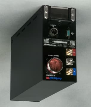
Click to zoom
Application Details
- Equipment Class
- TNB - Licensed Non-Broadcast Station Transmitter
- Date of Grant
- Nov 25, 2001
- Application Purpose
- Original Equipment
- Date of Application
- May 09, 2001
- Frequency Range
- 1030.00000000 - 1030.00000000
- Country
- United States
Documents & Files
Document Text
Text extracted from the exhibit documents filed with the FCC. Open a document above to read the original.
Users Manual
Preliminary $12.00 U.S. $12.00 U.S. Pilot’s Guide for the Pilot’s Guide for the Traffic Alert/Advisory System Model SKY899 Traffic Alert/Advisory System Model SKY899 SKY899 Pilot’s Guide A Preliminary Eyes That Never Blink ™ Early Traffic Alert/Advisory Systems In the early days of flight, pilots were equipped with all they needed for effective collision avoidance–a sharp pair of eyes. But increasing traffic at higher speeds led to the development of TCAS I and II (Traffic Alert and Collision Avoidance Systems) which were too expensive for most regional airlines, business aircraft, and general aviation aircraft. SKYWATCH ® BFGoodrich Avionics Systems, Inc. recognized the need for an alternative to expensive TCAS systems and developed the SKYWATCH model SKY497 Traffic Advisory System (TAS) and the SKYWATCH HP model SKY899 TAS/TCAS I. The SKYWATCH HP can be installed as a TAS to provide most of the capabilities of TCAS I, but at a significantly lower cost, making it practical for small aircraft. The SKYWATCH HP can also be installed as a TCAS I. In addition to its TCAS I capability, SKYWATCH HP improves upon the SKY497 by adding ADS-B surveillance, a larger display range ( 15 nmi), and a higher maximum closure rate (1200 kn). Proven Experience BFGoodrich Avionics Systems, Inc. has been involved in the development of collision warning programs since the early 1980’s. In 1985, BFG began development of an enhanced collision warning system for the Navy’s T-34C training aircraft. Based largely on the success of the Navy project, BFG was selected to validate the specifications for TCAS I. As a result, BFG’s original TCAS I unit, the TCAS791 was the first TCAS I to be TSO’d, first to receive a full, unrestricted STC, first to fly, and first to be delivered. Preliminary $12.00 U.S. Pilot’s Guide for the Traffic Alert/Advisory System Model SKY899 © Copyright 2001 BFGoodrich Avionics Systems, Inc. SKYWATCH ® , EYES THAT NEVER BLINK ™ , and STORMSCOPE ® are trademarks of BFGoodrich Avionics Systems, Inc. Designed and manufactured in the United States of America by Methods and apparatus disclosed and described herein have been developed solely on company funds of BF- Goodrich Avionics Systems, Inc. No government or other contractual support or relationship whatsoever has existed which in any way affects or mitigates proprietary rights of BFGoodrich Avionics Systems, Inc. in these developments. Methods and apparatus disclosed herein may be subject to U.S. Patents existing or applied for. BFGoodrich Avionics Systems, Inc. reserves the right to add, improve, modify, or withdraw functions, design modifications, or products at any time without notice. BFGoodrich Avionics Systems, Inc. 5353 52nd Street, S.E. Grand Rapids, MI 49512 USA (616) 949-6600 Fax (616) 285-4224 www.bfgavionics.com (800) 253-9525 or SKY899 Pilot’s Guide ii Preliminary Safety Summary These warnings and cautions appear later in this guide and are repeated here for emphasis: To avoid power surges that could damage the SKY899 and the optional WX-1000, start your engines before turning on the SKY899. If the SKY899 is in SKYWATCH mode, the display will not auto- matically switch into Stormscope mode to display thunderstorms or Stormscope errors. Use the remote SKYWATCH/Stormscope mode switch to periodically check for thunderstorms or Stormscope errors. The SKY899 relies on information obtained from transponders in nearby aircraft. The SKY899 does not detect or track aircraft which are not equipped with an operating Air Traffic Control Radar Beacon System (ATCRBS) transponder. The SKY899 does not track intruder aircraft approaching at a closure rate greater than 1200 knots. Some traffic within the chosen display range may not be displayed due to traffic prioritizing, antenna shielding, or ground intruder filtering. Optimum SKY899 performance is realized when intruder aircraft are reporting their altitude (via a mode C or other altitude reporting transponder). Do not attempt evasive maneuvers based solely on traffic informa- tion on the display. Information on the display is provided to the flight crew as an aid in visually acquiring traffic; it is not a replacement for Air Traffic Control (ATC) and See & Avoid techniques. CAUTION page 3-5 page 3-6 page 3-6 page 3-6 page 3-6 CAUTION page 3-1 page 3-6 SKY899 Pilot’s Guide iii Preliminary Table of Contents SectionPage List of Illustrations....................................... v List of Tables...............................................vi Abbreviations & Acronyms............................ vii Chapter 1, System Description................... 1-1 General Description................................................................... 1-1 Transmitter Receiver Computer (TRC)........................................ 1-2 Directional Antenna................................................................... 1-2 Display...................................................................................... 1-3 Interaction of Major Components............................................... 1-4 Functional Description............................................................... 1-4 Features..................................................................................... 1-6 Chapter 2, Controls & Indicators................. 2-1 Introduction.............................................................................. 2-1 Controls, Indicators, & Symbols................................................. 2-1 Controls Required for the Stormscope Option............................... 2-5 Controls & Indicators for an Alternate Display............................. 2-6 Aural Announcements................................................................ 2-6 Chapter 3, Operating Instructions............... 3-1 Introduction.............................................................................. 3-1 Turn On the SKY899................................................................. 3-1 Run the Operator-Initi…
Text truncated - open the document above for the full version.
Users Manual
Chapter 3 – Operating Instructions SKY899 Pilot’s Guide 3-5 Preliminary With each press of the button, the screen changes to display the traffic detected within the chosen display range. The numerical value of the chosen display range ( 2, 6, or 15 nm) is displayed next to the button. The SKY899 continues to track up to 35 intruder aircraft within its maximum horizontal surveillance range ( 35 nmi radius) regardless of the display range selected. Change the Vertical Display Mode You can change the vertical display mode when the SKY899 is in normal operating mode. 1. Press the vertical display mode button to toggle between above, normal, below, and unrestricted. With each press of the button, the screen changes to display the traffic detected within the chosen vertical display mode (figure 1-5). The name of the chosen vertical display mode ( ABV, NRM, BLW, or UNR) is displayed next to the button. The SKY899 continues to track up to 35 intruder aircraft within its maximum vertical surveillance range (± 10,000 ft) regardless of the vertical display mode selected. Switch Between SKYWATCH & Stormscope If you have a Stormscope WX-1000 installed with the SKY899, you can switch between SKYWATCH and Stormscope screens (figures 1-2 and 1-3) using the remote SKYWATCH/Stormscope mode switch. Once in Stormscope mode, you can use the buttons on the display bezel to control Stormscope functions. If the SKY899 is in SKYWATCH mode, the display will not auto- matically switch into Stormscope mode to display thunderstorms or Stormscope errors. Use the remote SKYWATCH/Stormscope mode switch to periodically check for thunderstorms or Stormscope errors. The SKY899 does not superimpose SKYWATCH data on top of Stormscope data or vice versa; however, if the SKY899 is in Stormscope mode and the SKY899 detects a TA, the display automatically switches to SKYWATCH mode until the TA goes away. Also, if the SKY899 is in Stormscope mode and the SKY899 detects a failure, a special SKY899 Failed screen appears that doesn’t have a TEST button label, but does display the message Change the Vertical Display Mode Chapter 3 – Operating Instructions SKY899 Pilot’s Guide 3-6 Preliminary “Press Any Key to Ack.” Pressing any button or waiting 10 seconds switches the SKY899 back to Stormscope mode. Observe the Display The SKY899 relies on information obtained from transponders in nearby aircraft. The SKY899 does not detect or track aircraft which are not equipped with an operating Air Traffic Control Radar Beacon System (ATCRBS) transponder. The SKY899 does not track intruder aircraft approaching at a closure rate greater than 1200 knots. Some traffic within the chosen display range may not be displayed due to traffic prioritizing, antenna shielding, or ground intruder filtering. Optimum SKY899 performance is realized when intruder aircraft are reporting their altitude (via a mode C or other altitude reporting transponder). Monitor the activity of any traffic displayed. Keep in mind the following points when watching traffic on the display: •Traffic Prioritizing – The SKY899 tracks up to 35 intruder aircraft simultaneously, but to reduce clutter, it displays only the 8 most threatening aircraft of those tracked. •Ground Intruder Filtering – If a radio altimeter is connected to the SKY899, no traffic symbols are displayed for traffic detected under 380 ft Above Ground Level (AGL) when your aircraft is below 1,700 ft AGL. •Refer to chapter 4 for a description of the TA criteria and other factors that affect the display of traffic symbols. Respond to Traffic Advisories Do not attempt evasive maneuvers based solely on traffic informa- tion on the display. Information on the display is provided to the flight crew as an aid in visually acquiring traffic; it is not a replacement for Air Traffic Control (ATC) and See & Avoid techniques. CAUTION Observe the Display Chapter 3 – Operating Instructions SKY899 Pilot’s Guide 3-7 Preliminary When the SKY899 issues a TA, look outside for the intruder aircraft. When you spot an intruder aircraft, use normal right- of-way procedures to maintain separation. Turn Off the SKY899 and the Optional WX-1000 Rotate the OFF/BRT knob on the display bezel counterclock- wise until the switch turns off. Operate the WX-1000 Without the SKY899 After removing the SKY899 for maintenance, maintenance personnel must install a jumper plug if you want to continue using the WX-1000. Operate the SKY899 Without the WX-1000 After removing the WX-1000 for maintenance, maintenance personnel will move the WX-1000 maintenance switch to the OVERRIDE (WX-1000 maintenance) position to allow contin- ued operation of the SKY899. Message Response When the SKY899 detects a fault, it determines whether the system has failed or is just degraded. A failed system can not perform any collision warning functions. A degraded system can perform some collision warning functions but may not be able to provide some features such as intruder position en- hancement via ADS-B (due to the loss of GPS communications). Respond to a Failed System In the case of a failed system, the SKY899 displays a Failed screen (figure 3-4). All errors indicated by a Failed screen prevent continued operation of the SKY899 in SKYWATCH mode; however, error #20, Barometric Altitude Input, is a recoverable error. For example, if you turn on and try to operate the SKY899 before you turn on the barometric altitude source and it comes on line, a SKY899 Failed screen appears with error #20 and continued operation of the SKY899 in SKYWATCH mode is not possible; but when you eventually turn on the barometric altitude source, the Failed screen disappears and operation returns to normal. Message Response Chapter 3 – Operating Instructions SKY899 Pilot’s Guide 3-8 Preliminary If you see a SKY899 Failed screen, respond as follows: 1. If the Barometric Altitude Input error (#20) occurs, make sure the barometric altitude source has been turned on and given enough time to warm up. M…
Text truncated - open the document above for the full version.
Users Manual
Traffic Alert/Advisory System SKY899 Installation Manual This manual contains installation instructions and recommended flightline maintenance information for the SKY899 Traffic Alert/Advisory System. This information is supplemented and kept current by Change Notices, Service Bulletins, and Service Memos published by BFGoodrich Avionics Systems. 009-11900-001 (Rev. A) BFGoodrich Avionics Systems, Inc.30 April 2001 5353 52 nd Street, S.E. Grand Rapids, MI USA 49512 Preliminary Preliminary A Rev. A ABOUT THIS MANUAL Chapter 1 – General Information This chapter includes equipment specifications and a functional description. It describes the various hardware configurations and includes a list of items furnished and items required but not supplied with the equipment. Chapter 2 - Installation This chapter contains instructions for unpacking the equipment and inspection for in-shipment damage. It also includes information required to locate, assemble and install the equipment. Chapter 3 – Installation Checkout This chapter contains instructions for doing post-installation and return to service checkout of the SKY899 using the BFGoodrich Avionics Systems TT391 Flightline Tester. Chapter 4 – Maintenance This chapter contains general flightline maintenance procedures. It includes periodic maintenance and troubleshooting; instructions for calibrating the directional antenna and instructions for the return of defective components. Appendix A – Signal and Cable Characteristics This appendix defines the electrical characteristics of all input and output signals. Appendix B – Environmental Qualification Form This appendix has the environmental qualification forms for the TRC899, NY156 & NY164 antennas, and WX-1000/SKY497 display. Appendix C – Installation Checkout Using The TCAS-201 Ramp Test Set This appendix contains instructions for doing post-installation and return to service checkout of the SKY899 using the IFR Systems TCAS-201 Ramp Test Set (with TCAS I firmware). Appendix D – Installation Checkout Using The TIC T-49C Flightline Tester This appendix contains instructions for doing post-installation and return to service checkout of the SKY899 using the TIC T-49C Flightline Tester. Appendix E – Using The Terminal Device This appendix contains instructions for using the Terminal Device for installation, testing or troubleshooting of the SKY899. Appendix F – Installation Checkout Using an Alternate Display This appendix contains instructions for doing post-installation and return to service checkout of the SKY899 using an Alternate Display. © Copyright 2001 BFGoodrich Avionics Systems, Inc. ____________________________ Trademarks Alodine ® is a registered trademark of Amchem Products, Inc. Flamemaster ® is a registered trademark of Flamemaster. HyperTerminal ® is a registered trademark of Hilgraeve, Inc. Mylar ® and Teflon ® are registered trademarks of DuPont. Procomm ® is a registered trademark of Datastorm Technologies, Inc. SKYWATCH ® HP and Stormscope ® are registered trademarks of BFGoodrich Avionics Systems, Inc. SKY899 Installation Manual i Rev. A LIST OF EFFECTIVE PAGES Dates of original and changed pages are:Original (Rev. A) .......................... 30 April 2001 NOTE The portion of the text affected by the change is indicated by a vertical line in the outer margins of the page. Changes to illustrations (other than diagrams and schematics) are identified with a miniature pointing hand. Shading is used to highlight the area of diagrams and schematics containing a change. Total number of pages in this publication consists of the following: PageChange No.No. Title Page ................................................................. 0 A Page ..................................................................... 0 i thru viii .................................................................... 0 1-1 thru 1-24 ............................................................. 0 2-1 thru 2-36 ............................................................. 0 3-1 thru 3-8 ............................................................... 0 4-1 thru 4-24 ............................................................. 0 A-1 thru A-14 ............................................................ 0 B-1 thru B-4 .............................................................. 0 C-1 thru C-6 .............................................................. 0 D-1 thru D-4 .............................................................. 0 E-1 thru E-6 .............................................................. 0 F-1 thru F-6............................................................... 0 INSERT LATEST CHANGED PAGES, DESTROY SUPERSEDED PAGES. Those responsible for maintaining this publication should ensure that all previous changes have been received and incorporated. Preliminary Preliminary SKY899 Installation Manual ii Rev. A FOREWORD This manual provides information intended for use by persons who, pursuant to current regulatory requirements, are qualified to install this equipment. Because installations vary depending on a particular aircraft, this manual is intended as a guideline. Standard installation practices prescribed in FAA Advisory Circular No. 43.13 must be followed. If further information is required, contact: BFGoodrich Avionics Systems Attn: Field Service Engineering 5353 52nd Street, S.E. Grand Rapids, MI USA 49512 Tel. (800) 453-0288 or (616) 949-6600 We welcome your comments concerning this manual. Although every effort has been made to keep it free of errors, some may occur. When reporting a specific problem, please describe it briefly and include the manual part number, the paragraph/figure/table number, and the page number. Send your comments to: BFGoodrich Avionics Systems Attn: Technical Publications 5353 52nd Street, S.E. Grand Rapids, MI USA 49512 Preliminary SKY899 Installation Manual iii Rev. A TABLE OF CONTENTS ParagraphPage Chapter 1 GENERAL INFORMATION 1.1INTRODUCTION .................…
Text truncated - open the document above for the full version.
Cover Letter(s)
Cover Letter to FCC Dear Sirs, BFGoodrich is submitting form 731, requesting equipment authorization for our Skywatch TRC899 Aircraft Collision Avoidance system. The unit to be authorized is the Radio/ Transmitter/ Receiver Box called the TRC899. This product is governed by the FCC through technical standards outlined in part 87(aviation services) of Title 47. We have notified the FAA about our intentions to manufacture and sell this piece of equipment to avionics distributors and dealers. The FAA per TSO C197 will certify our system. This TSO is granted only after a unit has been designed and verified to comply with RTCA documents DO-197A, DO-160D and DO-178B. RTCA DO-197A ( Minimum Performance Standards For an Active Traffic Alert and Collision Avoidance System – Active TCAS I – For Revenue Passenger Operations) is a minimum operation standard for collision warning products for use on aircraft. DO-160D is the document describing the environmental tests to be run on the unit. DO-160D includes descriptions of the tests (that the FAA requires) to measure unintended radiation out of the unit through the panel and cables. DO-178B is a software standard that our unit is designed to comply with. Our unit has been tested to the standards set forth in Title 47 part 87 subpart D. We have submitted data in accordance with Title 47 part 2.1033(c) on form 731. We have made tests and provided data in accordance with parts: 2.1046, 2.1047, 2.1049, 2.1051, 2.1053 and 2.1055. Attached in appendix A is the letter that we sent to the FAA informing them of our intent to certify and manufacture the TRC899. Attached in Appendix B is the revised letter of intent that we sent to the FAA. CR-392 APPENDIX A – LETTER OF INTENT FOR SKYWATCH TRC899 February 26, 1999 Ms. Brenda S. Ocker Federal Aviation Administration Chicago ACO/Aircraft Certification Office Systems & Equipment Branch, ACE-115c 2350 E. Devon Avenue, Room 323 Des Plaines, Illinois 60018 Subject:Letter of Intent for Skywatch II TRC899 (SKY899) Dear Brenda; This letter is to inform you of our intent to seek TSO authorization for the Skywatch II TRC899 Traffic Advisory System. The SKY899 is an active, traffic advisory system that assists the pilot in seeing and avoiding other aircraft. It will employ technologies currently being utilized in the TCAS791/791A Collision Avoidance System and the SKY497 Traffic Advisory System. The system will consist of three major components, a remote mounted Transmitter-Receiver- Computer (TRC), a display device, and a directional antenna. The system functionality is based on the current SKY497 design with the following modifications: The SKY899 will use the 52 dBm (nominal) peak RF transmitter power outlined in TSO C147, Traffic Advisory System Airborne Equipment. This will allow for increased range surveillance when compared to the SKY497. Therefore, we have increased the maximum display range to 15 nautical miles for this system. This system will also have the ability to receive and decode Automatic Dependent Surveillance-Broadcast (ADS-B) messages transmitted in the 1090 MHz Mode S extended message format. The TRC899 will also provide data, via an ARINC 429 interface, to a Mode S transponder or other system capable of transmitting Mode S extended squitter messages, for the purpose of transmitting own aircraft ADS-B information. The certification plan for the SKY899 is outlined in BFGoodrich Avionics Systems Document, Certification Plan, Skywatch II , BFGAS Part Number 016-11908-001. This document is included for your review. Due to the use of the increased transmitter power, this system will fall under interference limiting requirements that were not applicable for the low power SKY497. As such it is our intent to follow the alternative approach outlined in the Interference Limiting Section of RTCA/DO-197A, Minimum Operational Performance Standards For An Active Traffic Alert and Collision Avoidance System (Active TCAS I) . The note under paragraph 2.2.6 Interference Limiting, states that “As an alternative to the above, an Active TCAS I may choose to transmit Mode S broadcast signals, in which case it would then appear to be an Active TCAS II and could therefore increase its power-rate limits to the limits specified for an Active TCAS II in RTCA DO-185.” Since this note was omitted from Appendix I of Traffic Advisory System TSO C147, we will be seeking a deviation to allow for its use with a Traffic Advisory System. If the deviation is granted, we feel that an approach similar to that used in the SKY497, where we guarantee to stay below the minimum rate-power limits associated with a certain number of TCAS II aircraft, would justify the elimination of the requirement to maintain a count of the number of TCAS II aircraft and thus remove the need for a 1030 MHz receiver in the system. To receive further guidance and technical information on such an approach, we have initiated contact with Ron Sandholm of MIT Lincoln Labs. We will also discuss the technical details of this approach with Ed Glowacki, of the FAA Tech Center, or another appropriate source as directed by your office. We will further update and seek formal approval from you on this approach, based on the results of our discussions with Mr. Sandholm and the FAA Tech Center. All TSO test procedures will be documented in the Skywatch II TSO Test Plans and Procedures document and submitted for your review and approval prior to the beginning of certification testing. A milestone schedule is included in the Certification Plan document that is enclosed with this letter. Sincerely, Marnie Sablan FAA Liaison Enclosures: Certification Plan, Skywatch II , BFGAS Part Number 016-11908-001 APPENDIX B – REVISED LETTER OF INTENT FOR SKYWATCH TRC899 July 25, 2000 Ms. Brenda S. Ocker Federal Aviation Administration Chicago ACO/Aircraft Certification Office Systems & Equipment Branch, ACE-115c 2350 E. Devon Avenue, Room 323 Des Plaines, Illinois 60018 Subject:Revised Letter …
Text truncated - open the document above for the full version.
Cover Letter(s)
Request of Confidentiality Dear Sirs, We would like to request that our FCC filing for equipment authorization for the PMY TRC899 be confidential. We request that you keep all schematics, block diagram, and parts lists/tune up information confidential. We are competing with several other manufacturers with equipment similar to ours. We believe that revealing our block diagram, tune up information and schematics could give our competitors proprietary information about how we implement certain functions in our design. Sincerely, Brent Locher BFGoodrich Avionics Systems Inc.
Cover Letter(s)
Mr. George Sakai Federal Aviation Administration Program Director for Spectrum Policy and Management, ASR-1 800 Independence Ave, SW Washington, DC 20591 Subject: Coordination Letter between FAA and FCC for Goodrich TRC 899 Dear Mr. Sakai, Goodrich Avionics Systems is seeking FCC equipment authorization for the TRC 899 collision avoidance system. In order to receive equipment authorization we need to write a letter informing the FAA of our intent to produce a piece of equipment that is authorized under FCC part 87. We request that you inform the FCC that the equipment that we intend to produce is acceptable to the FAA. Goodrich is requesting FCC equipment authorization for our Skywatch TRC899 Aircraft Collision Avoidance system. The unit to be authorized is the Radio/ Transmitter/ Receiver Box called the TRC899. This product is governed by the FCC through technical standards outlined in part 87(aviation services) of Title 47. We have notified the FAA about our intentions to manufacture and sell this piece of equipment to avionics distributors and dealers. The FAA per TSO C197 will certify our system. This TSO is granted only after a unit has been designed and verified to comply with RTCA documents DO-197A, DO-160D and DO-178B. RTCA DO-197A ( Minimum Performance Standards For an Active Traffic Alert and Collision Avoidance System – Active TCAS I – For Revenue Passenger Operations) is a minimum operation standard for collision warning products for use on aircraft. DO-160D is the document describing the environmental tests to be run on the unit. DO-160D includes descriptions of the tests (that the FAA requires) to measure unintended radiation out of the unit through the panel and cables. DO-178B is a software standard that our unit is designed to comply with. Our unit has been tested to the standards set forth in Title 47 part 87 subpart D. We have submitted data in accordance with Title 47 part 2.1033(c) on form 731. We have made tests and provided data in accordance with parts: 2.1046, 2.1047, 2.1049, 2.1051, 2.1053 and 2.1055. The FCC equipment identification will be “PMY TRC899”. The antenna is a 4-pole directional antenna. Its transmit gain pattern is very similar to a standard monopole antenna. Its receiver gain pattern is also very similar to a standard monopole but it incorporates two outputs, which allow the direction of the received signal to be determined. The output power of the TRC899 is typically between 53 dBm and 55 dBm and will never exceed 57 dBm (at the transmitting unit). This typically is connected to the antenna through cables of approximately 2 dB of loss so that the effective radiated output power is between 51 dBm and 53 dBm out of a monopole equivalent antenna. The transmitter signal has characteristics as defined in DO-197A. This signal has a FCC emission designator of “ PON”. The transmitted signal is pulse-modulated bursts at 1030 MHz ± 200 KHz. There are three pulses sent out in each burst. Each RF pulse is 800 ns wide. The three pulses are sent out over a 23 usec interval. There is a maximum of 7 pulse bursts sent out every second. The amplitude of the pulses may be varied in level. The highest peak power out of the TRC is 500 (57 dBm) Watts. Each 800 nsec wide pulse has a risetime and falltime of approximately 100 nsec. The Bandwidth designator is “20M0”. The FAA requires that every a DO-197A compliant system meet certain spectral requirements. Every unit that is manufactured is tested to ensure compliance with this specification. The specification is as follows: The spectrum of an active TCAS I Mode –C interrogation shall not exceed the following: Frequency Difference (MHz from carrier) Maximum Relative Power (dB down from peak) Between 0.7 and 53 Between 5 and 2020 Between 20 and 6040 Over 6060 Attached in appendix A is the letter that we sent to the FAA informing them of our intent to certify and manufacture the TRC899. Attached in Appendix B is the revised letter of intent that we sent to the FAA. Sincerely, Brent Locher Staff Engineer Goodrich Avionics Systems CR-392 APPENDIX A – LETTER OF INTENT FOR SKYWATCH TRC899 February 26, 1999 Ms. Brenda S. Ocker Federal Aviation Administration Chicago ACO/Aircraft Certification Office Systems & Equipment Branch, ACE-115c 2350 E. Devon Avenue, Room 323 Des Plaines, Illinois 60018 Subject:Letter of Intent for Skywatch II TRC899 (SKY899) Dear Brenda; This letter is to inform you of our intent to seek TSO authorization for the Skywatch II TRC899 Traffic Advisory System. The SKY899 is an active, traffic advisory system that assists the pilot in seeing and avoiding other aircraft. It will employ technologies currently being utilized in the TCAS791/791A Collision Avoidance System and the SKY497 Traffic Advisory System. The system will consist of three major components, a remote mounted Transmitter-Receiver- Computer (TRC), a display device, and a directional antenna. The system functionality is based on the current SKY497 design with the following modifications: The SKY899 will use the 52 dBm (nominal) peak RF transmitter power outlined in TSO C147, Traffic Advisory System Airborne Equipment. This will allow for increased range surveillance when compared to the SKY497. Therefore, we have increased the maximum display range to 15 nautical miles for this system. This system will also have the ability to receive and decode Automatic Dependent Surveillance-…
Text truncated - open the document above for the full version.
Contact Information
Applicant
Brent Locher(Staff Engineer)
Technical Contact
BFGoodrich Avionics Systems, Inc.Brent Locher
[email protected]614-825-2243
1105 Schrock Road · Columbus, Ohio · United States
Non-Technical Contact
BFGoodrich Avionics Systems, Inc.Marnie Sablan
[email protected]614-825-2254
Technical Specifications
| # | Rule Parts | Frequency Range | Power Output | Emission | Tolerance |
|---|---|---|---|---|---|
| 1 | 87 | 1.03 GHz - 1.03 GHz | 500 W | 20M0PON | 200.0000000000 ppm |
Other Applications from L-3 Communications, Avionics Systems
PMYADR7050
Nov 08, 2006Avionics VHF Communications Transceiver
Equipment Class
TNB - Licensed Non-Broadcast Station Transmitter
PMYTRC497
Feb 13, 2002SkyWatch Traffic Advisory System
Equipment Class
TNB - Licensed Non-Broadcast Station Transmitter