PN9GX-1Personal Computer
Saint Song Corporation
Click to zoom
Application Details
- Equipment Class
- JBC - Part 15 Class B Computing Device/Personal Computer
- Date of Grant
- Dec 04, 2001
- Application Purpose
- Original Equipment
- Date of Application
- Dec 04, 2001
- Equipment Note
- Personal Computer
- Company
- Saint Song Corporation
- Country
- Taiwan
Documents & Files
Document Text
Text extracted from the exhibit documents filed with the FCC. Open a document above to read the original.
Users Manual
EXHIBIT C User Manual 1 User’s Guide Mini Book PC For Intel & Windows Compatible Operating Systems 23 Disclaimer The manufacturer shall not be liable for errors contained herein or for incidental consequential damages in connection with the furnishing, performance, or use of this material. This document contains proprietary information which is protected by copyright. All rights reserved. No part of this document may be photocopied, reproduced, or translated into another language without the prior written consent of the manufacturer. The manufacturer reserves the right to revise this publication and to make changes from time to time in the contents hereof without obligation to notify any person of such revision or changes. The manufacturer also reserves the right to change the specification without notice and may therefore not coincide with the contents of this document. The manufacturer assumes no responsibilities with regard to the performance or use of third party products. Trademarks Microsoft and MS-DOS is a registered trademark of Microsoft Corporation. Windows and Windows Sound System are trademarks of Microsoft Corporation. Intel and Intel Pentium III are registered trademarks of Intel Corporation. All other brands or product names mentioned in this manual are trademarks or registered trademarks of their respective companies. Document Version 1.0 Printed in Taiwan May 2001 FCC Notice This equipment generates and uses radio frequency and may cause interference to radio and television reception if not installed and used properly. This has been tested and found to comply with the limits of a Class B computing device in accordance with the specifications in Part 15 of FCC Rules. These specifications are designed to provide reasonable protection against such interference in a residential installation. However, there is no guarantee that interference will not occur in a particular installation. If this equipment does cause harmful interference to radio or television reception, which can be determined by turning the equipment off and on, the user is encouraged to try to correct the interference by one or more of the following measures: n Reorient or relocate the receiving antenna. n Increase the separation between the equipment and receiver. n Connect the equipment into an outlet on a circuit different from that to which the receiver is connected. n Consult the dealer or an experienced radio/TV technician for help. aThe use of shielded I/O cables is required when connecting this equipment to any and all optional peripheral or host devices. Failure to do so may violate FCC rules. Changes or modification not covered in this manual must be approved in writing by the manufacturer’s Regulatory Engineering department. Changes or modifications made without written approval may void the user’s authority to operate this equipment. Canadian Doc Notice Le present appareil numerique n’emet pas de bruits radioelectriques depassant les limites applicables aux appareils numeriques de la class B prescrites dans le Reqlement sur le brouilage radioelectrique edicte par le Ministere des Communications du Canada. 45 Welcome to Your User’s Guide Welcome to the Mini-Book PC User’s Guide. This manual covers everything you need to know in learning how to use your Mini Book personal computer. This manual also assumes that you know the basic concepts of DOS, Windows and the PC. Note that your computer comes in different configurations and options so some of the features mentioned in this manual might not be included or slightly different from the one you got. Contact your dealer for more information and latest update. What Does This Manual Covers? This manual covers the following information: Chapter 1Gives introduction on the features and parts of your computer. Chapter 2Provides instructions on how to prepare your computer for immediate use. Chapter 3Describes how to operate the built-in features of your computer. Chapter 4Illustrates how to connect external desktop devices to your computer. Chapter 5Explains how to use the System BIOS Setup program. Chapter 6Offers instructions on how to maintain and troubleshoot your computer. Telephone and modem information Some telephone companies require that you notify the local business office when you hook up a modem to their lines. The internal modem complies with part 68 of the FCC rules. 67 Accompanying Your Computer Congratulations for having purchased your new Mini-Book PC. You will start doing a lot of great and fun things with your computer. Along with your computer comes several items which you need to check inside the box. See photo below and compare: Figure 0-1 Standard Out-of-the-Box Computer Items Where to Find Additional Information To find additional information and technical support for your computer, please first contact your dealer. 89 Turning Off Your Computer / 32 Chapter 3 Learning the Basics / 34 Starting Your Operating System / 35 Using the Floppy Disk Drive / 35 Working with the Built-in Hard Disk / 36 How to Access the CD-ROM Drive / 36 Using the Built-in Internal Modem / 38 Using the Built-in Internal LAN / 40 Chapter 4 Connecting to Other Devices / 41 Using a Serial Port / 42 Connecting to a Parallel Printer / 42 Connecting to Your TV / 43 Using USB Devices / 44 Chapter 5 The BIOS Setup Program / 46 Entering the BIOS Setup Program / 47 Using the Standard CMOS Setup / 48 Using the Advanced CMOS Setup / 49 Using the Power Management Setup / 51 Using the PCI/Plug and Play Setup / 52 Using the Peripheral Setup / 54 Using the Auto-Detect Hard Disks / 55 Using the System Password / 55 Auto Configuration with Optimal Settings / 56 How to Exit the Setup Program / 56 How to Upgrade the BIOS / 56 Contents Welcome to Your User’s Guide / 5 What Does This Manual Covers? / 5 Where to Find Additional Information / 5 Accompanying Your Computer / 7 Chapter 1 Getting Acquainted / 10 Introduction / 12 Inside Features of the Computer / 12 Overall View of the Comp…
Text truncated - open the document above for the full version.
Block Diagram
EXHIBIT E Block Diagram A A AA Title Page Cover Shee t& Block Diagram 370PGA Socket GTL Termination Clock Synthesizer 82810-DC100 System Memory FWH Super I/O ATA33 IDE Connectors USB Connectors SYS CON RST/PG Kybrd / Mouse VGA Graphics Connectors DC/DC Voltage Regulators DC/DC PWM_ REG Pullup Resistors and Unused Gates Decoupling 1 2 , 3 4 5 6 ,7 , 8 9 12 , 13 14 15 17 18 19 20 21 22 23 24 25 26 27,28 CGI REV:1.1 DATACTRLADDR Term VRM ICH Keyboard Mouse Floppy Parallel SIO Clock LAN8139C Block Diagram SO- DIMM Modules USB Port 1 USB Port 2 Audio/Modem AMC'97 CTRLDATA ADDR IDE Primary IDE Secondary UltraDMA/33 USB PCI CNTRL PCI ADDR/DATA AC'97 Link FirmWare Hub LPC Bus GMCH Display Cache Memory Out Device Digital Video 370-Pin Socket Processor PCI CNTRL PCI ADDR/DATA PCI CNTRL PCI ADDR/DATA Serial 1 Serial 2 Infrared RS/232 RS/232 AMR_connector 82810 82801AA W83627AF 16 10 10 ICH0 CD Connector 11 TV S-Video Out Encoder Audio CODEC LAN8039C Cover Sheet EPC2B
Cover Letter(s)
From: trc168 [[email protected]] Sent: Wednesday, December 05, 2001 6:57 PM To: Mike Kuo Subject: Re: SAINT SONG CORP, FCC ID:PN9GX-1 AN01T1561 Dear Mike : As I understand the P15.33(b)(1) ,the highest frequency generated, means the frequency of the oscillator used in the device,not CPU speed. the oscillator is 100MHz used in this device, so I think it is not necessary to investigate up to 5GHz. But I still invetigated and found the emissions all under limit more than 10 dB . But I like to know if I am correct about the understanding of "the highest frequency" .Because I am going to send the other mini PC for the application later. Thank you for your information . Should I send the data to you ? Jacob Lin ----- Original Message ----- From: Mike Kuo <[email protected]> To: <[email protected]> Sent: Thursday, December 06, 2001 8:39 AM Subject: FW: SAINT SONG CORP, FCC ID:PN9GX-1 AN01T1561 > Dear Jacob: > > One question for this application. > > M.Kuo > > -----Original Message----- > From: CERTADM > Sent: Wednesday, December 05, 2001 4:38 PM > To: '[email protected]' > Subject: SAINT SONG CORP, FCC ID:PN9GX-1 AN01T1561 > > > Notice_content > ------------- > Question #1: The highest frequency used and/or generated for this device is > 650MHz. In accordance with 15.33(b)(1) table, the highest frequency range > should be investigated is 5000MHz. The test report indicated the radiated > emission test was scanned from 30 - 1000MHz only. Please provide additional > radiated emission data from 1000-5000MHz at 3 meter distance. > > Best Regards > > Mike Kuo / TCB Certifier > The items indicated above must be submitted before processing can continue > on the above referenced application. Failure to provide the requested > information within 60 days of the original e-mail date may result in > application dismissal and forfeiture of the filing fee. Also, please note > that partial responses increase processing time and should not be submitted. > Any questions about the content of this correspondence should be directed to > the e-mail address listed below the name of the sender. >
ID Label/Location Info
List of Exhibit EXHIBIT A Sample Label EXHIBIT B Test Report EXHIBIT C User Manual EXHIBIT D Circuit Diagram EXHIBIT E Block Diagram EXHIBIT F Photographs of EUT EXHIBIT A Sample Label LABEL Format: This device complies with Part 15 of the FCC Rules Operation is subject to the following two conditions: (1) This device may not cause harmful interference, and (2) This device must accept any interference received, including interference that may cause undesired operation. FCC ID: PN9GX-1 Model No.: GX-1 LABEL Size: 45 X 20 mm LABEL Position: LABEL
Test Report
EXHIBIT B Test Report Test Report --------------------------------------------------------------------------------------------------------- 2/16 Report No.: S1115172 Training Research Co., Ltd., TEL: 886-2-26461146, Fax: 886-2-26461778 Contents Chapter 1 Introduction Description of EUT .............................................................................................................. 3 Configuration of Test Setup ................................................................................................. 4 List of Support Equipment ................................................................................................... 6 Chapter 2 Conducted Emission Test Test Condition and Setup ..................................................................................................... 8 Conducted Test Placement ................................................................................................... 9 Chapter 3 Radiated Emission Test Test Condition and Setup .................................................................................................... 10 Radiated Test Placement ........................................................................................................11 Appendix A : Conducted test result..............................................................................................................12 Appendix B : Radiated test result ...............................................................................................................15 Test Report --------------------------------------------------------------------------------------------------------- 3/16 Report No.: S1115172 Training Research Co., Ltd., TEL: 886-2-26461146, Fax: 886-2-26461778 Chapter 1 Introduction Description of EUT: The EUT is similar to a CD player. It weighs only 1.9 pounds. You can take it easily with you to the places you might work with. Cappuccino GX1 includes all the standard I/O ports like parallel port for connecting printers, and 2 USB ports for other devices. This EUT included CPU Pentium III 650MHz, 64MB DRAM, 24X CD-ROM, 6GB HDD. I/O port: VGA port x 1, Serial port x 1, LPT port x 1, MODEM RJ-11 port x 1, USB port x 2, Phone jack x 1, MIC jack x 1, LAN port x 1, Mouse port x 1, Keyboard port x 1, S-Video Out jack x 1, Video Out jack x 1. There are one CD-ROM (Quanta Storage Inc. SCR-242) and one Hard Disk (IBM, Travelstar, DJSA-205) also able to be used in this EUT. These two devices has been meet the requirements. ) Test method: Pretest was found that the emission of operating mode is worse than standby mode. So, The final test is made at the operating mode. Before test set the modem and LAN to transmit and receive data. For radiation pretest, there were three kinds displays applied as following: (A) VGA mode: uses three different resolutions: (1) 1600 x 1200, (2) 1024 x 768, (3) 800 x 600. The 1024 x 768 was the sorst case. (B) V-terminal mode: use 800 x 600 resolution. (C) S-terminal mode: use 800 x 600 resolution. The emission of V and S terminal were not much different. The final test in OATS, we tested: (A) VGA mode at 1024 x 768 resolution. (B) V-terminal mode. This adaptor is a full range power voltage. After verifying the 110V and 230V, found that it is not much different during radiation test. But during the conduction test, there were 110V and 230V test data supplied. Each of the data was tested at three different resolutions as radiation, the S and V terminal were terminated. During testing, the EUT was operated at “transmitting” and “receiving” mode simultaneously. The test placement as the photographs showed is the worst case emission placed. (If the emission is close to the ambient, the resolution BW and view resolution will be reduced and the data will be recorded by detection of maximum hold peak mode.) The testing configuration of test setup is showing in the next page. Test Report --------------------------------------------------------------------------------------------------------- 4/16 Report No.: S1115172 Training Research Co., Ltd., TEL: 886-2-26461146, Fax: 886-2-26461778 Configuration of test setup(Test mode: VGA ) Connections: EUT: *Serial Port --- a mouse with 1.9m long, shielded and no ferrite bead data cable. *Monitor Port --- a monitor with 1.5m length data cable. *Keyboard Port --- a keyboard with 1.7m length data cable. *Mouse Port --- a mouse with 1.8m long of data cable. *Printer port --- a printer with 1.80m length data cable. *USB Port A --- a mouse with 1.5m long, shielded and no ferrite bead data cable. *USB Port B --- a mouse with 1.5m long, shielded and no ferrite bead data cable. *Speak-Out Jack --- a pairs of Microphone&Earphone with 1.2m long wire. *MIC Jack --- a pairs of Microphone&Earphone with 1.2m long wire. *S-Video Out Jack --- with a 2m long non-shielded cable that terminal. *Video Out jack --- with a 2m long non-shielded cable that terminal. *Line Jack --- via a 15m long, non-shielded, no ferrite bead, RJ-11C cable to the PABX located remotely. *LAN Port --- via a 15m long, non-shielded, no ferrite bead, RJ-45 cable to another LAN card that installed in another PC located in far-end. *Power jack --- via a power cable is 1.48m long, non-shielded, with a ferrite bead that connect with a power adapter (Trade name: ILAN ELEC. LTD.., Model No.: F17003B, Input: AC100-240~ 50-60Hz, 1.8A, Output: DC 18V, 3A ) that via a 1.75long, non-shielded, with aferrite bead power cable connect the power source. Printer Power Source Mouse Keyboard Monitor EUT Mouse USB Mouse USB Mouse Microphone &earphone To Far-end PABX To another PC Located Remotely UTP Port Test Report --------------------------------------------------------------------------------------------------------- 5/16 Report No.: S1115172 Training Research Co., Ltd., TEL: 886-2-26461146, Fax: 886-2-26461778 Configuration of test setup(Test mode: TV ) Connections: EUT: *Serial Port --- a mouse with 1.9m long, shielded and no ferrite bea…
Text truncated - open the document above for the full version.
Test Setup Photos
Test Report --------------------------------------------------------------------------------------------------------- 9/16 Report No.: S1115172 Training Research Co., Ltd., TEL: 886-2-26461146, Fax: 886-2-26461778 Conducted Test Placement: (Photographs) Test Report --------------------------------------------------------------------------------------------------------- 11/16 Report No.: S1115172 Training Research Co., Ltd., TEL: 886-2-26461146, Fax: 886-2-26461778 Radiated Test Placement: (Photographs)
Contact Information
Applicant
David Wang(Manager)
Test Firm
Training Research Co., Ltd.Jack Tsai
Technical Specifications
| # | Rule Parts | Frequency Range | Power Output |
|---|---|---|---|
| 1 | 15B | - | - |
Other Applications from Saint Song Corporation

PN9TX-3
Jan 13, 2002Mini Book PC
Equipment Class
JBC - Part 15 Class B Computing Device/Personal Computer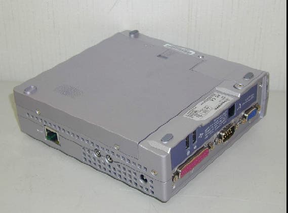
PN9CG-I
Jul 25, 2001Pocket PC
Equipment Class
JBC - Part 15 Class B Computing Device/Personal Computer