Click to zoom
Application Details
- Equipment Class
- JBP - Part 15 Class B Computing Device Peripheral
- Date of Grant
- Jan 20, 2002
- Application Purpose
- Original Equipment
- Date of Application
- Jan 20, 2002
- Equipment Note
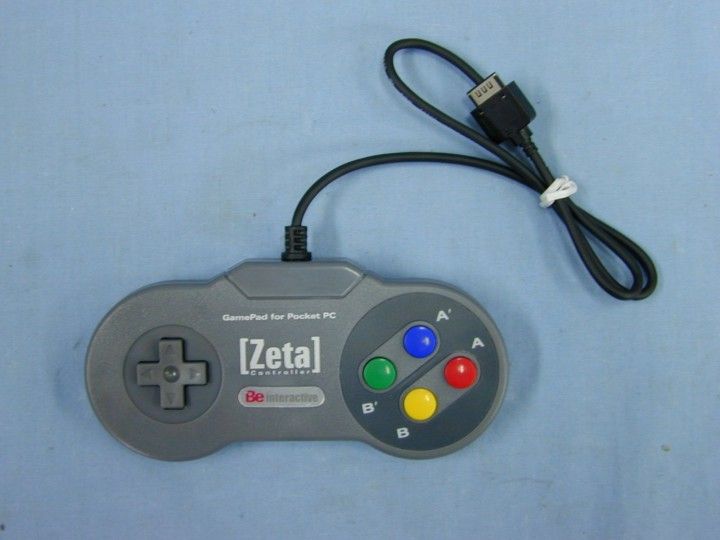
- Game Pad
- Company
- Be Interactive Co Ltd
- Country
- South Korea
Documents & Files
Select a file to view
Users Manual
Block Diagram
External Photos
ID Label/Location Info
Internal Photos
Test Report
Test Setup Photos
Contact Information
Applicant
Byung-Hun Eum(Manager)
Test Firm
Estech Co., Ltd.Ike Chung
Technical Specifications
| # | Rule Parts | Frequency Range | Power Output |
|---|---|---|---|
| 1 | 15B | - | - |
Other Applications from Be Interactive Co Ltd
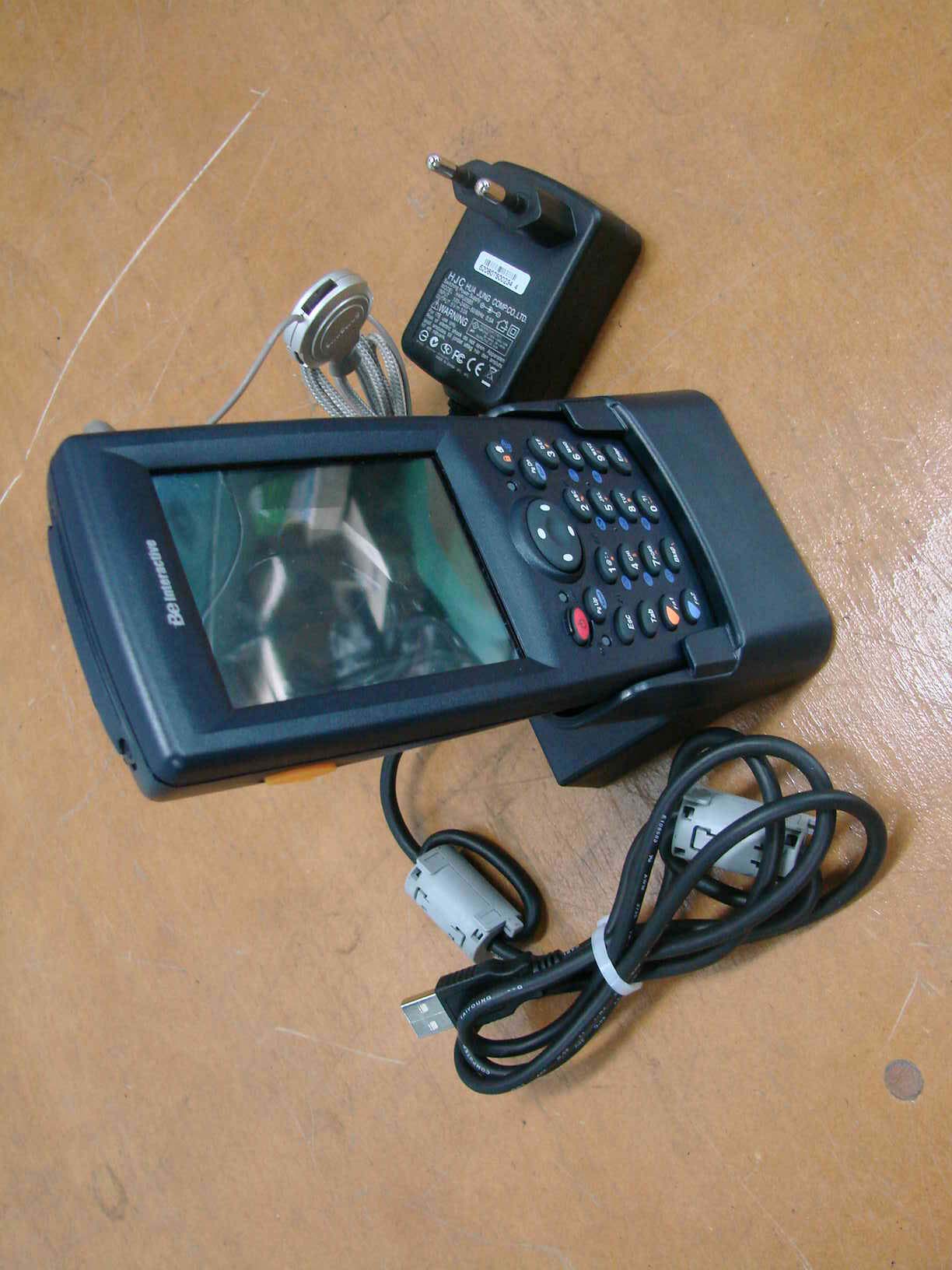
PNGUD720
Sep 17, 2007Industrial Mobile Computer
Equipment Class
DSS - Part 15 Spread Spectrum Transmitter