FCCID.CO- FCC ID Database
HomeCompaniesEquipment ClassesSearch

© 2026 FCC ID Database. All rights reserved.

AboutContactData sourced from FCC public records
  1. Home/
  2. Comtec Systems Co., Ltd./
  3. PNMCT-170

PNMCT-170LCD Monitor

Comtec Systems Co., Ltd.
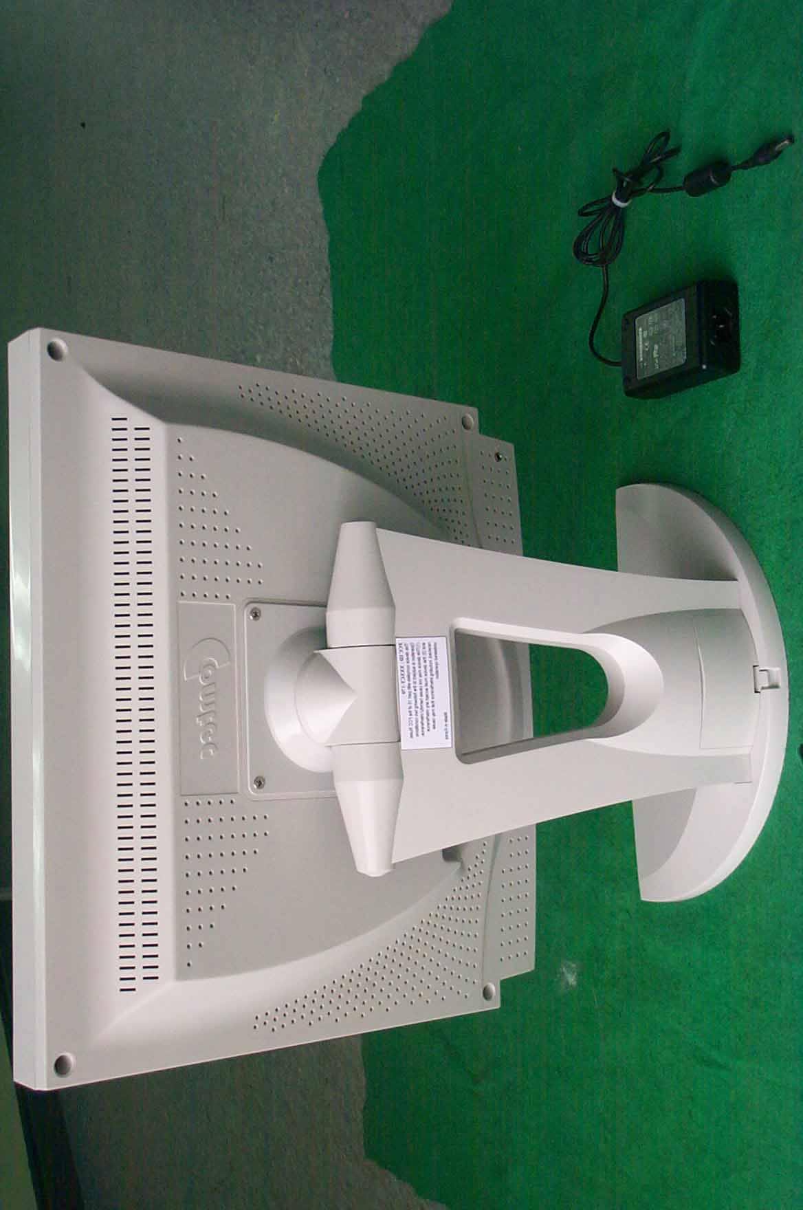
LCD Monitor - FCC ID PNMCT-170 - Comtec Systems Co., Ltd.
Click to zoom

Application Details

Equipment Class
JBP - Part 15 Class B Computing Device Peripheral
Date of Grant
May 20, 2001
Application Purpose
Original Equipment
Date of Application
May 20, 2001
Equipment Note
LCD Monitor
Company
Comtec Systems Co., Ltd.
Country
South Korea

Documents & Files

Select a file to view

Users Manual

↗

Block Diagram

↗

External Photos

↗

ID Label/Location Info

↗

Internal Photos

↗

Test Report

↗

Test Setup Photos

↗

Document Text

Text extracted from the exhibit documents filed with the FCC. Open a document above to read the original.

Users Manual

1 USER USERUSER USER’S GUIDE S GUIDES GUIDE S GUIDE 2 OPERATION . This equipment has been tested and found to comply with the limits for a Class B digital device, pursuant to part 15 of the FCC Rules. These limits are designed to provide reasonable protection against harmful interference in a residential installation. This equipment generates, uses and can radiate radio frequency energy and, if not installed and used in accordance with the instructions, may cause harmful interference to radio communication. However, there is no guarantee that interference will not occur in a particular installation. If this equipment does cause harmful interference to radio or television reception, which can be determined by turning the equipment off and on, the user is encouraged to try to correct the interference by one or more of the following measures : - Reorient or relocate the receiving antenna. - Increase the separation between the equipment and receiver. - Connect the equipment into an outlet on a circuit difference from that to which the receiver is connected. - Consult the dealer of an experienced radio/TV technician for help. NOTE : The manufacturer is not responsible for any radio or TV interference caused by unauthorized modifications to this equipment. Such modifications could void the user’s authority to operate the equipment. 3 4 How to install ................................... 2 How to control the menu on screen ............................... 4 Pivot (*option) ................................... 8 Power Supply and Power Management System ................... 9 A Trouble Shooting ...................................... 10 Specifications ..................................... 10 Mode Supported ...................................... 12 Analog PC Graphics Port Signal Descriptions ....................... 13 Base Ass’y Alteration and Installation ................................. 14 5 vivid screen and crisp color. • It is easy to control the resolution from SXGA(1280*1024), XGA(1024*768), SVGA(800*600) to VGA (640*480). It detects and configures automatically the optimal characteristics of input frequency. • While receiving the output RGB video signal from computer, the monitor can display it up to 16 million colors. • The user can set screen automatically by one-touch pressing. (AUTO key) • The user can adjust the angle(90°) of the TFT LCD monitor according to customer’s convenience. It must install Pivot software to make 4:3 frame to 3:4 frame. • It provides a power saving function (DPMS). • It provides “Plug-and-Play” so you may install this monitor easily. • The emission of electromagnetic waves that can be harmful to the human body has been minimized. 6 • Do not open the inside of the monitor. If needed, contact with A/S center. 2. If the following problem occurs, disconnect the plug and contact our service center. • When some or whole part of monitor is exposed to excessive humidity or moisture. • In case there is a strange sound, smell, or smoke inside the monitor. If the power cable is damaged, be extremely careful when disconnecting the plug. How to install 1. Attention Point to install • Do not use this product on an unstable place. - This product may fall, causing serious damage to the product. • In the well-ventilated place, it is a good place where it is installed. • Do not put the monitor in a damp place and close to a heating installation. - It may be cause of electric shock and breakdown. • Do not put the metal or heavy goods on this product. - It may be cause of electric shock, a fire and breakdown. • Do only install the power cord and adapter in the enclosed box. 7 • Driver Diskette • Pivot Install CD (*option) If any of the above items are damaged or missing, please contact your customer service center as soon as possible. 3. Installing the monitor 3.1 Connecting the LCD monitor with computer 1. Turn off the computer before connecting the monitor 2. Connect the signal cable from PC signal port to Monitor signal port. 3. Connect the audio cable from PC audio port to Monitor audio port. 4. Plug in the AC/DC adapter, and connect the DC connector to the DC Port on the back of the monitor. 5. Turn on the computer, then “Plug-and-Play” will run automatically. At this time, you should install the driver in driver diskette. • Speaker Cable 8 How to control the menu on screen <Picture 2> 1. Names of front side, and their use • AUTO Key (AUTO) : Operates AUTO Adjust without opening OSD menu. • Menu Key (MENU) : Opens the OSD display and closes OSD menu display. <Picture 1> UP DOWN RIGHT LEFT POWER SWITCH POWER LED SELECTMENU AUTO 9 value of the selected item in submenu. / opens Volume menu without opening OSD menu. • Select Key (SELECT) : Select Icons or functions in OSD menu and submenu. • Power Key (POWER) : Turns the monitor on / off. • Power LED : Green(normal operation). Yellow (DPMS mode). No MENU on display OSD Main MENU Sub-MENU AUTO Operates auto - configuration Directly - - MENU Opens OSD Main menu Closes OSD main menu Returns to OSD main menu UP Opens Brightness menu - - DOWN Opens Contrast menu - - RIGHT Opens Volume menu Moves icon to the Right in OSD Menu Increases the value of the selected item LEFT Opens Volume menu Moves icon to the Left in OSD Menu Decreases the value of the selected item SELECT - Selects item Selects value and return to OSD main Menu <Picture 3> 10 <Picture 3> <Picture 4> 2. How to Control OSD menu The OSD menu appears when the user presses the OSD calling button(MENU). The user can select the function and configure the selected function that best fits the computer environment. If no item is selected after the OSD menu is brought up, it automatically disappears after 15 seconds. Moreover, the user can operate directly Brightness Menu, Contrast Menu and Volume Menu without calling OSD Menu. ITEM Contents RIGHT LEFT Brightness Adjusts brightness Gets brighter Gets darker Contrast Adjusts contrast Screen color becomes more vivid Screen color becomes d…

Text truncated - open the document above for the full version.

Block Diagram

> CT-170 BLOCK DIAGRAM MAIN B/D Back Light Inverter TFT LCD Module Switch B/D Speaker * 2 LVDS data VGA signal Sound DC Power Key/LED/Sound Sound > M/B BLOCK DIAGRAM gmZAN1 OSD Controller LVDS Tr MCU EEPROM EEPROM (DDC) DC Reg CN5 CN4 CN2 CN6 CN1 Ext Power Controller Back light Controller LCD POW Controller CN3 CN7 Analog R.G.B. POWER DC 12v STEREO SOUND 12 V 5 V 3 .3 V LCD POW & LVDS DATA EXT POWER BACK LIGHT POW/CTRL KEY IN / LED DISPLAY SOUND CONTROLLER KEY / LED SOUND DATA DC POWER PHONE / SPEAKER CN2 MAIN BOARD SWITCH BOARD

External Photos

SK TECH CO., LTD. Page 1 of 2 SKT SKTOS-01066 FCC ID : XXXCT-170 External Photographs of EUT SK TECH CO., LTD. Page 2 of 2 SKT SKTOS-01066 FCC ID : XXXCT-170

ID Label/Location Info

SK TECH CO., LTD. Page 1 of 1 SKT SKTOS-01066 FCC ID : XXXCT-170 FCC ID Sample Label & Location Information LABELLING REQUIREMENTS PER ∫∫∫∫ ∫∫∫∫∫∫∫∫ ∫∫∫∫2.928 The Label shown shall be permanently affixed at a conspicuous location on the device and be readily visible to the user at the time of purchase. FCC ID : PNMCT-170 This device complies with part 15 of the FCC Rules. Operation is subject to the following two conditions: (1) This device may not cause harmful interference, and (2) this device must accept any interference received, including interference that may cause undesired operation.

Internal Photos

SK TECH CO., LTD. Page 1 of 7 SKT SKTOS-01066 FCC ID : XXXCT-170 Internal Photographs of EUT SK TECH CO., LTD. Page 2 of 7 SKT SKTOS-01066 FCC ID : XXXCT-170 SK TECH CO., LTD. Page 3 of 7 SKT SKTOS-01066 FCC ID : XXXCT-170 SK TECH CO., LTD. Page 4 of 7 SKT SKTOS-01066 FCC ID : XXXCT-170 SK TECH CO., LTD. Page 5 of 7 SKT SKTOS-01066 FCC ID : XXXCT-170 SK TECH CO., LTD. Page 6 of 7 SKT SKTOS-01066 FCC ID : XXXCT-170 SK TECH CO., LTD. Page 7 of 7 SKT SKTOS-01066 FCC ID : XXXCT-170

Test Report

SK TECH CO., LTD. Page 1 of 13 SKT SKTOS-01066 FCC ID : XXXCT-170 Certificate of Compliance Test Report No.: SKTOS-01066 NVLAP CODE : 200220-0 Applicant: Comtec Systems Co., Ltd. Applicant Address: 779-10, Daelim 3-Dong, Youngdungpo-Ku, Seoul, Korea Product: LCD Monitor FCC ID: PNMCT-170 Model No.: CT-170 Receipt No.: SKE20010406-266 Date of receipt: Apr. 06, 2001 Date of Issue: Mar. 14, 2001 Testing location: SK TECH CO., LTD. 820-2, Wolmoon-Ri, Wabu-Up, Namyangju-Si, Kyunggi-Do, Korea Test Standards: ANSI C63.4 / 1992 Rule Parts: FCC part 15 Subpart B Equipment Class : Class B Digital Device Peripheral Test Result: The above mentioned product has been tested and passed. Prepared by:E.K.Seong Tested by:K.W.Song/Engineer Approved by: J.Y.Hyun /Lab.Manager Signature Date Signature Date Signature Date Other Aspects : Abbreviations : · OK, Pass = passed · Fail = failed · N/A = not applicable ☞ ☞☞ ☞ •This test report is not permitted to copy partly without our permission. •This test result is dependent on only equipment to be used. •This test result is based on a single evaluation of one sample of the above mentioned. •This test report must not be used by the client to claim product endorsement by NVLAP or any agency of the U.S Government. • We certify that this test report has been based on the measurement standards that is traceable to the national or International standards. NVLAP Lab. Code: 200220-0 SK TECH CO., LTD. Page 2 of 13 SKT SKTOS-01066 FCC ID : XXXCT-170 》》 》》》》 》》 Contents 《《 《《《《 《《 Contents 2 List of Tables 2 List of Figures 2 List of Photographs 2 1. General 3 2. Test Site 3 2.1 Location 3 2.2 List of Test and Measurement Instruments 4 2.3 Test Date 4 2.4 Test Environment 4 3. Description of the tested samples 5 3.1 Rating and Physical Characteristics 5 3.2 Submitted Documents 5 4. Measurement Conditions 6 4.1 Modes of Operation 6 4.2 List of Peripherals 6 4.3 Type of Used cables 7 4.4 Test Setup 7 4.5 Uncertainty 7 5. EMISSION Test 8 5.1 Conducted Emissions 8 5.2 Radiated Emissions 12 》 》》 》List of Tables Table 1 List of test and measurement Equipment 4 Table 2 Test Data, Conducted Emissions 11 Table 3 Test Data, Radiated Emissions 13 》 》》 》List of Figures Figure 1 Spectral Diagram, LINE-PE 9 Figure 2 Spectral Diagram, Neutral-PE 10 SK TECH CO., LTD. Page 3 of 13 SKT SKTOS-01066 FCC ID : XXXCT-170 1. General This equipment has been shown to be capable of compliance with the applicable technical standards and was tested in accordance with the measurement procedures as indicated in this report. We attest to the accuracy of data. All measurements reported herein were performed by SK Tech Co., Ltd. and were made under Chief Engineer’s supervision. We assume full responsibility for the completeness of these measurements and vouch for the qualifications of all persons taking them. 2. Test Site SK TECH Co., Ltd. 2.1 Location 820-2, Wolmoon Ri, Wabu-Up, Namyangju-Si, Kyunggi-Do, Korea The test site is in compliance with ANSI C63.4/1992 for measurement of radio interference. SK TECH CO., LTD. Page 4 of 13 SKT SKTOS-01066 FCC ID : XXXCT-170 2.2 List of Test and Measurement Instruments Table 1 : List of Test and Measurement Equipment z Conducted Emissions Kind of Equipment Type S/N Calibrated until EMI Receiver ESHS10 862970/019 02.2002 Artificial Mains Network KNW-407 M63284 07.2001 EMI Receiver ESHS10 385871/002 11.2001 Artificial Mains Network ESH3-Z5 836679/018 11.2001 Conducted Cable N/A N/A 07.2001 z Radiated Emissions Kind of Equipment Type S/N Calibrated until EMI Receiver ESVS 10 825120/013 02.2002 Spectrum Analyzer R3361A 11730187 07.2001 Amplifier 8447F 3113A05153 05.2001 Log Periodic Antenna UHALP9107 91071238 02.2002 Biconical Antenna BBA9106 N/A 02.2002 Open Site Cable N/A N/A 07.2001 Antenna Mast 5907 N/A N/A Antenna & Turntable controller 5906 91X519 N/A Amp & Receiver connection cable N/A N/A 07.2001 Amp & Spectrum connection cable N/A N/A 07.2001 50Ω Switcher MP59B M93083 07.2001 2.3 Test Date Date of Application : Apr. 06, 2001 Date of Test : Apr. 20, 2001 ~ Apr. 23, 2001 2.4 Test Environment See each test item’s description. SK TECH CO., LTD. Page 5 of 13 SKT SKTOS-01066 FCC ID : XXXCT-170 3. Description of the tested samples The EUT is LCD MONITOR. 3.1 Rating and Physical Characteristics z Panel Type : TFT z Panel Size : 17.0” z Resolution : 1280 x 1024 z Display Size : 337.92(W) x 270.33(H) mm z Dot Pitch : 0.264mm x 0.264mm z Color : 16.7M colors (24bit color mode) z Contrast : TYP : 350 : 1 CR z Brightness : TYP : 200 cd/m 2 z Compatibility : IBM, MAC z Input Signal : Analog R.G. B (0.7 Vp-p) z Connection Cable : D-sub 15 pin z Plug-and Play : VESA DDC 1,2B z Power Management System : VESA DPMS (Display Power Management Signaling) z Horizontal Frequency : 31.5 ~ 80 KHz z Vertical Frequency : 56 ~ 75Hz z Main Body Dimension : 424(W) x 199(D) x 456(H) mm z Gross Weight : 7.2 Kg(Net), 10Kg (Gross) z Power Consumption : 44W (Max.) z Input Current : AC 100V ~ 240V, 50/60Hz z Temperature limit for Operation / Storage : 0 ~ 50°C / -20 ~ 65°C z Humidity limit for Operation / Storage : 20 ~90% / 5~90% 3.2 Submitted Documents N/A SK TECH CO., LTD. Page 6 of 13 SKT SKTOS-01066 FCC ID : XXXCT-170 4. Measurement Conditions Operating of EUT voltage is 12V DC supplied by the adaptor which is structural element for EUT. ( Adaptor Input Voltage : AC 120V, 60Hz) 4.1 Modes of Operation The EUT was in the following operation mode during all testing; EUT is connected with PC by video interface cable. Tested in mode of playing audio file & displaying “H” on the screen. 4.2 List of Peripherals Description Manufacturer Model Name Serial No. FCC ID Personal Computer H.P Brio 600/650 SG3603857 DoC Printer H.P 2225C 3132S00310 DSI6XU2225 Keyboard Jing Mold LKB-0107 90602892 N/A Mouse 1 Logitech M-S48 LZA93274466 DZL211153 Mouse 2 A4 Tech AM-5E 951237243 H8GAM555P Mouse 3 Logitech M-BE55 LZE02551778 DoC Joystick Logitech J-ZA10 LZS01651409 N/A Mic LG Electronics N/A N/A N/A Adaptor (for …

Text truncated - open the document above for the full version.

Test Setup Photos

SK TECH CO., LTD. Page 1 of 2 SKT SKTOS-01066 FCC ID : XXXCT-170 Test set up photos Photograph 1: Setup for Conducted Emissions SK TECH CO., LTD. Page 2 of 2 SKT SKTOS-01066 FCC ID : XXXCT-170 Photograph 2: Setup for Radiated Emissions

Contact Information

Applicant

Jun-Eui Hong(Manager)
[email protected]82-32-521-7001Fax: 82-32-521-7008

Test Firm

SK Tech Co., Ltd.Jae-Yeong Hyun
[email protected]82-346-576-2204Fax: 82-346-576-2205

Technical Specifications

#Rule PartsFrequency RangePower Output
115B--

Other Applications from Comtec Systems Co., Ltd.
LCD Monitor - FCC ID PNMCT-150 - Comtec Systems Co., Ltd.
PNMCT-150

LCD Monitor

Jan 17, 2002

Equipment Class

JBP - Part 15 Class B Computing Device Peripheral