PNZ1101TWireless Tire Pressure Sensor
Xilor Inc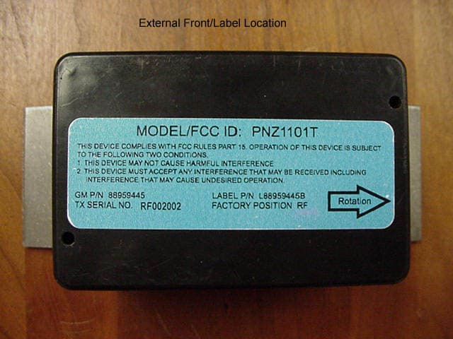
Click to zoom
Application Details
- Equipment Class
- DSC - Part 15 Security/Remote Control Transmitter
- Date of Grant
- Mar 17, 2002
- Application Purpose
- Original Equipment
- Date of Application
- Mar 17, 2002
- Equipment Note
- Wireless Tire Pressure Sensor
- Frequency Range
- 355.00000000 - 355.00000000
- Company
- Xilor Inc
- Country
- United States
Documents & Files
Document Text
Text extracted from the exhibit documents filed with the FCC. Open a document above to read the original.
Users Manual
8 DISCLAIMER The information contained here is considered accurate. However, Xilor makes no warranty or guarantee whether expressed or implied regarding the accuracy of the data, the results to be obtained from the use thereof, or that any such use will not infringe upon a patent. Under no circumstances shall Xilor be liable for incidental, conse- quential or other damages arising out of the use or handling of this product or the failure of the device to operate in a specific applica- tion. © Xilor ® Inc. 1400 Liberty Street Knoxville, TN 37909 www.rfmicrolink.com www.xilor.com Tel: (865) 546-9863 Fax: (865) 546-8324 1 rev.3/02 GM is a registered trademark of General Motors ® Xilor ® Inc. Wireless Tire Pressure Sensors MODEL PNZ1101T Part #88959444 (Yellow LR) Part #88959445 (Blue RF) Part #88959446 (Green LF) Part #88959447 (Orange RR) WARNING: These wireless tire pressure sensors are not sold or intended as a substi- tute for routine visual inspection ( including but not limited to tire wear cuts, bruises, tread separation) , inflation checks and normal tire mainte- nance. Read this manual completely before using product. Important warnings are contained herin. 2 OVERVIEW The Xilor® after-market wireless tire pressure sensors were de- signed to monitor pressure inside each tire and report a low tire condition via a coded RF transmission to the cars receiver. A unique code number is factory programmed into each transmitter. The code contains sensor ID information as well as the status of the on-board patent pending integrated pressure switch and optional low battery IC monitor. Low battery monitor option requires a receiver with a low battery detection feature. If tire pressure drops below the set point of the pressure switch the transmitter will send a code corresponding to a low tire condition. A low tire warning lamp in the cars dash will illuminate to indicate that a low tire condition occurred. These sensors will instantly send a low tire condition upon speeds greater than 5 MPH. If tire pressure is above the setpoint then at speeds greater than 5MHP sensors will transmit a status code approxi- mately every 18 seconds. 3V lithium batteries powr sensors and should provide years of service. Batteries can not be replaced by end user. Any attempt to open the sensors enclosure voids all warranties. COMPATIBILITY Sensors are compatible with GM Corvette OEM receivers, GM Part# 10161858, and other aftermarket receivers with similar code format. INSTALLATION Installation below should be performed by an authorized dealer or tire service center. 1) Before removal of tires. Turn on ignition without starting car. The LTPWS dash lamps should illuminate for 2 seconds then extin- guish. If this does not occur then consult receiver documentation for troubleshooting and abort installation of sensors until receiver or dash lamp trouble is diagnosed. If both lamps illuminate and then extinguish then you may proceed with installation. 7 FCC INFO. FCC ID:PNZ1101T This device complies with Part 15 of the FCC Rules. Operation is sub- ject to the following two conditions: (1) this device may not cause harmful interference, and (2) this device must accept any interference received, including interference that may cause undesired operation. _____________________________________________________ This equipment has been tested and found to comply with the limits for a Class-B digital device, pursuant to Part 15 of the FCC rules. These limits are designed to provide reasonable protection against harmful interference in a residential installation. This equipment gen- erates, uses and can radiate radio frequency energy and, if not in- stalled and used in accordance with the instructions, may cause harmful interference to radio communications. However, there is no guarantee that interference will not occur in a particular installation. If this equipment does cause harmful interference to radio or television reception, which can be determined by turning the equipment off and on, the user is encouraged to try to correct the interference by one or more of the following measures: 1) Reorient or relocate the receiving antenna 2) Increase the separation between the equipment and receiver. 3) Connect the equipment into an outlet on a circuit different from that to which the receiver is connected. 4) Consult the dealer or an experienced radio/TV technician for help. _____________________________________________________ This equipment has been certified to comply with the limits for a Class-B computing device, pursuant to FCC Rules. In order to main- tain compliance with FCC regulation s, shielded cables must be used with this equipment. Operation with non-approved equipment or un- shielded cables is likely to result in interference to radio and TV recep- tion. Changes and modifications by the user to the equipment without the approval of the manufacture could void the users authority to operate this equipment. 6 This page intentionally left blank 3 2) Label on top of each transmitter indicates the direction of forward ro- tation. Strap each transmitter around center of wheel with sensor posi- tioned at valve stem location and counter weight opposite that of sen- sor. Make sure each color coded transmitter is installed on the correct wheel by the factory position indicated on the sensor label with the com- mon abbreviation for Left Rear (LR), Left Front (LF), Right Rear (RR), and Right Front, (RF). Install tires onto wheels and mount to car. In- flate each tire but keep pressure below the setpoint of the sensor. For example the set point is 25psig +/- 2psi so inflate to 21psig to ensure you are below the set point as your gauge may not be a precision type instrument or set point tolerance my be at the lower end. 3) Turn on ignition without starting car. The LTPWS dash lamps should illuminate for 2 seconds then extinguish. Reset receiver to clear DTC history per receivers owners manual. LTPWS dash lamps will stay on continuo…
Text truncated - open the document above for the full version.
Block Diagram
50Ω Planar Antenna System Matching Network Low Pass Filter Encoder/MPU SAW Stabilized RF Oscillator System Block Diagram. Pressure Switch Acceleration switch 1.85 dB 50 ohm resistive pi pad. Provides attenuation and isolation.
Operational Description
OPERATIONAL DESCRIPTION The Xilor® after-market wireless tire pressure sensors were designed to monitor pressure inside each tire and report a low tire condition via a coded RF transmission to a receiver located inside the cars dash. A unique code number is factory programmed into each transmitter. The code contains sensor ID information as well as the status of the on-board patent pending integrated pressure switch and optional low battery IC monitor. Low battery monitor option requires a receiver with a low battery detection feature. While the car is driven above 5MPH if the tire pressure drops below the set point of the pressure switch the transmitter will send a code corresponding to a low tire condition approximately every 18 seconds. A low tire warning lamp in the car dash will illuminate to indicate that a low tire condition occurred. These sensors will send a low tire condition, if detected, at a speed greater than 5 MPH then cycle approximately every 18 seconds. If tire pressure is above the set-point then at speeds equal to or greater than 5MPH sensors will transmit a status “o.k.” code approximately every 18 seconds. With vehicle stopped the transmitters instantly cease operation and go into a power saving sleep mode. 3V lithium batteries power sensors. Batteries can not be replaced by end user. ©2002 Xilor Inc.
Schematics
1234 A B C D 4321 D C B A 0 Xilor Inc 1400 Liberty St Knoxville TN 37909 0 Title Size:Number: Date: Revision: Sheetof A All Rights Reserved COPYRIGHT XILOR INC GP5 2 GP4 3 GP3 4 GP2 5 GP1 6 GP0 7 U2 PIC12C508/SN 12 GND50 OHM RF IN ANT1 PLANAR SPIRAL ANTENNA Q2 C5 C7 C6 C2 10pF R3 6.8M R4 33K R5 150 C1 10pF C4 0.1uF C8 10pF L1 L2 GNDGND GND GND GND VCC R1 47 C3 10000pF GND GND VCC GND R6 1M R2 6.8M VCC GND GND 2 1 B1 BR2477A 3V GND VCC C9 1000pF IN 6 7 7 5 5 GND 4 GND 3 GND 2 GND 1 GND 8 X1 XILRSAW5MM X2 20kHz C10 10pF 2 1 B2 BR2477A 3V GND VCC 1 1 2 2 3 3 SW1 PSW25 GND 12 SW2 ASW2-3 GND C12 10pF GND C11 10pF GND out 1 vss 3 vdd 2 U1 MN1382-GGND VCC R7 100 C13 .1uF GND C14 10pF GND GNDGND R8 470 R10 470 R9 10
Test Report
FCC PART 15, SUBPART C TEST METHOD: ANSI C63.4-1992 TEST REPORT for Wireless Tire Pressure Sensor Model PNZ1101T OEM Manufacture: Xilor Inc 1400 Liberty St. Knoxville, TN 37909 (865) 546-9863 DATE: 3-15-2002 Table of Contents: Page Purpose and Report Summary3 Test Equipment settings and measurements Device flat measurements4 Device end measurements 5 Device side measurements 6 Device correction factors7 Scope capture of pulse widths8 Occupied bandwidth plot9 Test Equipment/Antenna/Calibration List10 REPORT SUMMARY This is an electromagnetic emission test report. The test report is based on testing performed by Philips Testing Lab. The tests were performed in order to determine whether the electromagnetic emissions from the equipment under test are within the specification limits defined by CFR Title 47, Part 15, Subpart C, sections 15.205, 15.209, and 15.231(e). Test Lab: Philips Testing 3029 Gov. John Sevier Hwy. Knoxville TN 37914 FCC Reg.# 90875 (exp. 1/28/03) NVLAP# 200409-0 exp. (6/30/02) (DBA Philips Consumer Electronics) Device(s) Tested: Wireless Tire Pressure Sensor Model or P/N(s): Model PNZ1101T Modifications: The EUT was not modified during the testing. Manufacturer: Xilor Inc 1400 Liberty St. Knoxville TN 37909 Test Date: 3-04-2002 Test Specifications: EMI requirements CFR Title 47, Part 15 Subpart C, Sections 15.205, 15.209, and 15.231 Test Procedure: ANSI C63.4: 1992 Test Deviation: The test procedure was not deviated from during testing. SUMMARY OF TEST RESULTS Conducted RF Emissions This test was not performed because the EUT runs off 3-volt lithium coin cells only and cannot be powered by any device that runs off of the AC public mains. Radiated RF Emissions Complies with the limits of CFR Title 47, Part 15, Subpart C, sections 15.205, 15.209, and 15.231 (e) END OF SUMMARY Radiated Emissions FCC Section 15.205 and 15.231 (e) Report # 20511 Test Distance 3 meters Date 3/04/2002 Test Conditions Unit FLAT EUT Wireless Tire Pressure Sensor/Transmitter Model PNZ1101T Mfg. Xilor FCC ID PNZ1101T Frequency (MHz) RAW Horiz dBuV RAW Vert dBuV Antenna Factor dBuV Duty Cycle Correction factor Horiz dBuV Vert dBuV Horiz Margin dBuV Vert Margin dBuV Limit dBuV 35553.651.5418.2 -9.94 61.8659.8-7.94-1069.8 71014.9413.8426.8 -9.94 31.830.7-18-19.149.8 106510.444.9431.8 -9.94 32.326.8-17.5-2349.8 14208.1410.633.9 -9.94 32.134.56-17.7-15.2449.8 177512.5411.8437.1 -9.94 39.739-10.1-10.849.8 Test Equipment Setup/Comments RBW & VBW= 100 kHz (30 - 1000 MHz) RBW & VBW= 1MHz (1 - 5 GHz) MEASUREMENTS WERE TAKEN FROM 30 MHz UP TO THE 10TH HARMONIC The above RAW readings are Peak readings. Duty cycle correction and antenna factors applied with results under Horiz and Vert. 5 Radiated Emissions FCC Section 15.205 and 15.231 (e) Report # 20511 Test Distance 3 meters Date 3/04/2002 Test Conditions Units Rotation arrow DOWN EUT Wireless Tire Pressure Sensor/Transmitter Model PNZ1101T Mfg. Xilor FCC ID PNZ1101T Frequency (MHz) RAW Horiz dBuV RAW Vert dBuV Antenna Factor dBuV Duty Cycle Correction factor Horiz dBuV Vert dBuV Horiz Margin dBuV Vert Margin dBuV Limit dBuV 35550.8453.0418.2 -9.94 59.161.3-10.7-8.569.8 71012.6417.2426.8 -9.94 29.534.1-20.3-15.749.8 10654.9413.0431.8 -9.94 26.834.9-23-14.949.8 14207.1415.0433.9 -9.94 31.139-18.7-10.849.8 17758.5412.0437.1 -9.94 35.739.2-14.1-10.649.8 Test Equipment Setup/Comments RBW & VBW= 100 kHz (30 - 1000 MHz) RBW & VBW= 1MHz (1 - 5 GHz) MEASUREMENTS WERE TAKEN FROM 30 MHz UP TO THE 10TH HARMONIC The above RAW readings are Peak readings. Duty cycle correction and antenna factors applied with results under Horiz and Vert. 6 Radiated Emissions FCC Section 15.205 and 15.231 (e) Report # 20511 Test Distance 3 meters Date 3/04/2002 Test Conditions Units Rotation arrow UP EUT Wireless Tire Pressure Sensor/Transmitter Model PNZ1101T Mfg. Xilor FCC ID PNZ1101T Frequency (MHz) RAW Horiz dBuV RAW Vert dBuV Antenna Factor dBuV Duty Cycle Correction factor Horiz dBuV Vert dBuV Horiz Margin dBuV Vert Margin dBuV Limit dBuV 35552.5453.7418.2 -9.94 60.862-9-7.869.8 71011.8416.9426.8 -9.94 28.733.8-21.1-1649.8 10655.5413.6431.8 -9.94 27.435.5-22.4-14.349.8 14208.7415.1433.9 -9.94 32.739.1-17.1-10.749.8 177511.5412.0437.1 -9.94 38.739.2-11.1-10.649.8 Test Equipment Setup/Comments RBW & VBW= 100 kHz (30 - 1000 MHz) RBW & VBW= 1MHz (1 - 5 GHz) MEASUREMENTS WERE TAKEN FROM 30 MHz UP TO THE 10TH HARMONIC The above RAW readings are Peak readings. Duty cycle correction and antenna factors applied with results under Horiz and Vert. 7 PEAK TO AVERAGE CORRECTION FACTOR Model PNZ1101T Carrier Frequency 355MHz Pulse Width (mS)Number of PulsesON Time (mS) 0.2210.22 0.2410.24 0.2620.52 0.6421.28 0.6621.32 0.6810.68 Max on Time (mS)4.26 Period (mS)13.38 Duty Cycle (Max on Time / Period)0.31838565 Correction Factor (dB) 20Log(Duty Cycle)-9.94 Philips Testing Service PCEC Asset # DescriptionModelS/NMfg.Cal DateCal Due T29655Spectrum Analyzer8568B2314A02597HP03-28-0103-28-02 T33179Oscilloscope223025795Tektronix04-23-0107-30-02 T33858Antenna31029003-2790EMCO05-26-0105-28-02 EX1523Antenna3110B9304-1679EMCO08-02-0011-02-01 EX1664Antenna31469502-3974EMCO08-02-0011-02-01 T33167RF Preselector85685A2724A00627HP12-29-0012-28-01 T37815Spectrum Analyzer8566B3014A06612HP05-17-0105-17-02 T33168Quasi Peak Adapter85650A2521A01001HP12-13-0012-013-01
Test Setup Photos
Table of Contents: Click Thumbnail for larger image OATS setup.........................Pages 2-3 OATS device on table............Pages 4-5
Contact Information
Applicant
Brian Miller(Compliance Coordinator)
Test Firm
Global Testing Laboratory, LLCCaile Gonzalez
Technical Specifications
| # | Rule Parts | Frequency Range | Power Output |
|---|---|---|---|
| 1 | 15.231(e) | 355 MHz - 355 MHz | - |
Other Applications from Xilor Inc
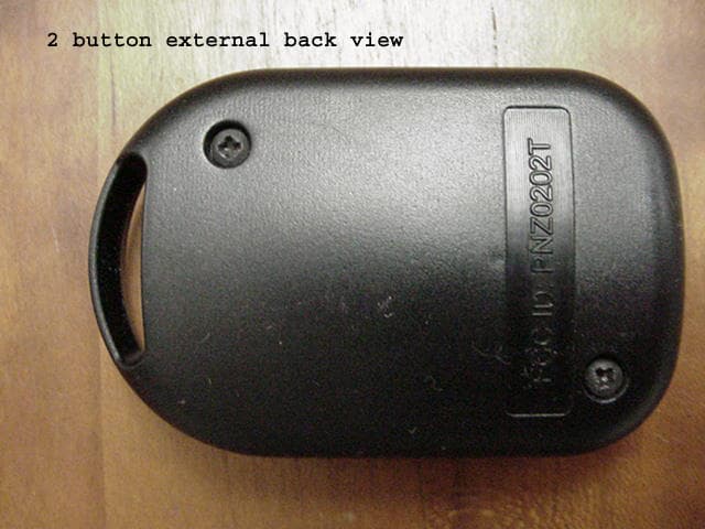
PNZ0202T
Apr 02, 2003Passive Keyless Entry (PKE)
Equipment Class
DCD - Part 15 Low Power Transmitter Below 1705 kHz
PNZ4XX
Aug 23, 2001Remote Control Transmitter
Equipment Class
DSC - Part 15 Security/Remote Control Transmitter