POIA750100Communications Receiver
Novra Technologies Inc.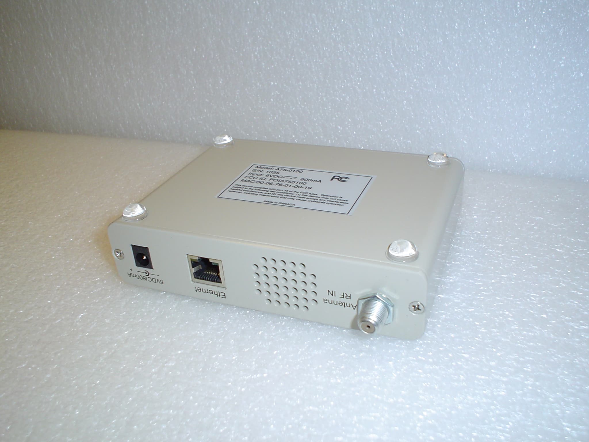
Click to zoom
Application Details
- Equipment Class
- CXX - Communications Rcvr for use w/ licensed Tx and CBs
- Date of Grant
- Jun 20, 2004
- Application Purpose
- Original Equipment
- Date of Application
- Jun 20, 2004
- Equipment Note
- Communications Receiver
- Frequency Range
- 57.00000000 - 803.00000000
- Company
- Novra Technologies Inc.
- Country
- Canada
Documents & Files
Document Text
Text extracted from the exhibit documents filed with the FCC. Open a document above to read the original.
Users Manual
Confidential and Proprietary Version DRAFT 2004APR29 1 of 11 Novra A75 Receiver Novra A75 Receiver Instructions Subject to change without notification CAUTION: Any changes or modifications not expressly approved by the manufacturer could void the user's authority to operate this equipment. These Files have been optimized for printing. Confidential and Proprietary Version DRAFT 2004APR29 2 of 11 Novra A75 Receiver Novra A75 Receiver Instructions Subject to change without notification Document version: DRAFT 2004APR29 ________________________________ Important- Please read this entire manual before installing or operating this product. ________________________________ Disclaimer While reasonable effort has been made in the preparation of this document to assure its accuracy, Novra Technologies Inc. assumes no responsibility for errors or omissions that may appear in this manual. Novra reserves the right to change the contents of this manual at any time without notice. Copyright © 2004 Novra Technologies Inc. All rights reserved. Information in this manual is subject to change without notice. No part of this manual may be reproduced or transmitted in any form, by photocopy, microfilm, xerography, or any other means, or incorporated into any information retrieval system, electronic or mechanical, for any purpose, without the express written permission of Novra Technologies Inc. For additional information or details on Novra's product offerings, please contact us at: North American Headquarters 1100-330 St. Mary Avenue, Winnipeg, MB Canada R3C-3Z5 t. 204.989.4724 f. 204.989.4640 e. [email protected] w. www.novra.com Confidential and Proprietary Version DRAFT 2004APR29 3 of 11 Novra A75 Receiver INDEX Page 1.0 MINIMUM SYSTEM REQUIREMENTS 3 2.0 INTRODUCTION 4 2.1 Principle Of Operations 4 3.0 INSTALLATION 5 4.0 MANAGEMENT CONSOLE SYSTEM CONFIGURATIONS 6 4.1 Configuring the A75 Data Receiver 6 6.0 A75 RECEIVER SPECIFICATIONS 8 APPENDIX Miscellaneous Terms and Definitions 9 1.0 Minimum System Requirements Your computer must have at least the following: • Processor: Pentium 566 MHz • RAM: 32 MB • Free disk space: 40 MB • Video: card and driver that support 256 or more colours • CD drive (required for software installation only) • Ethernet network interface card (NIC): 100 Mbps (100 BaseT) NOTE: - The receiver may work with system parameters below those specified but performance ma y be lacking. NOTE: - Performance will be dependant on other applications that your computer is running. Confidential and Proprietary Version DRAFT 2004APR29 4 of 11 Novra A75 Receiver 2.0 INTRODUCTION 2.1 Principles of Operation Somewhere in the world is a location that transmits your signal, along with many others, to your location and others. Your A75 sifts through all the signals for your signal, a DVB data stream. The A75 then de-encapsulates the IP information from the DVB stream and forwards it onto its final destination via a 100 Base-T Ethernet link. The A75 also transmits status packets to your computer where the A75 Management Console is located. The A75 Management Console is used to configure addresses, specify tuning parameters and select DVB information streams (PIDS). Once configured, the A75 will retain its settings and continue to forward data transmitted to you by your service provider even after restarting the A75 or your computer. The A75 Receiver is meant to run in the background. In most cases, once the options have been set, you will have no need to change them. Confidential and Proprietary Version DRAFT 2004APR29 5 of 11 Novra A75 Receiver 3.0 INSTALLATION 8-VSB Novra A75 100BaseT IP over Ethernet Windows Macintosh xnix DTV Multiplex Figure 1: A75 Hardware Connections 1) Connect the S75 Receiver to the RG6 coax cable that is attached your outdoor antenna. CAUTION: There are grounding requirements and other safety considerations associated with your outdoor antenna. Be sure to follow all local electrical standards and codes when installing and using an antenna. Confidential and Proprietary Version DRAFT 2004APR29 6 of 11 Novra A75 Receiver 2) Connect the 6 VDC adapter to the A75 . 3) Connect the Crossover Ethernet cable (Null-modem) between your computer's 100 BaseT NIC card and the A75. (Or the A75 can be connected to the computer via a Hub with regular Ethernet cables.) 4) On your computer, create a file folder called "A75." The file folder can be under "Program Files" or in any other location. Note: The system will create additional files containing various configuration aspects as they are created. The system will locate these additional files in the same directory as the A75 Management Console.exe program. 5) Copy the file A75 Management Console.exe from the CD ROM to the "A75" file folder. 6) Shortcuts can be created if desired through the normal Windows procedures. 7) Open (run) the A75 Management Console.exe and proceed to section 4.0. Confidential and Proprietary Version DRAFT 2004APR29 7 of 11 Novra A75 Receiver 4.0 MANAGEMENT CONSOLE SYSTEM CONFIGURATIONS 4.1 Configuring the A75 Data Receiver The data receiver configuration is very straightforward and can be shown in four basic steps: 1. Open (run) the A75 Management Console application 2. Configure the receiver IP addresses. 3. Set the receive channel. 4. Set the PID. Each of these three basic steps is presented below. Step 2: In figure 2, the A75 receiver IP addresses are configured according to the LAN at the receive site. Figure 2: Receiver IP Addresses Step 3: In figure 3, the receiver is tuned to channel 14, to match the broadcast modulator. Confidential and Proprietary Version DRAFT 2004APR29 8 of 11 Novra A75 Receiver Figure 3: Set the Channel Step 4: In figure 4, the PID is selected to match the data PID defined in the transmitting end. Figure 4: Set the PID Confidential and Proprietary Version DRAFT 2004APR29 9 of 11 Novra A75 Receiver 5.0 A75 RECEIVER SPECIFICATIONS Receiver o Receiving Frequency: 54 to 806 MHz o ATSC Channels: 2…
Text truncated - open the document above for the full version.
Cover Letter(s)
1100 - 330 St. Mary Avenue, Winnipeg, Manitoba, Canada R3C 3Z5 / Phone (204) 989-4724 / Fax (204) 989-4640 April 28, 2004 Federal Communications Commission Office of Engineering and Technology Equipment Approval Services Request for Confidentiality Attached form 731 – Application FCC ID: POIA750100 Dear Sir or Madam: Novra Technologies Corp. does not wish to publicly disclose certain technical information which is enclosed with the application. This material contains critical trade secrets and we request that the Commission withhold this information from public inspection pursuant to the provisions of Section 0.457(d) and 0.459 of the Commissions Rules, and section 552(b)(4) of the freedom of information act. Material to be held confidential: File Name Description A75 Schematic Circuit Schematics A75 Operational Description Description of operation A75 Block Diagram Block Diagram of the Device A75 Parts List S Parts List and Bill of Materials The above listed information is confidential and is not available to the public or end user. We have previously certified a similar device FCC ID: POIS750100 satellite receiver. Sincerely, Nathan Jacob Director Hardware Development
Cover Letter(s)
Response to TCB Findings 1. Please specify the label material. The label material is 3M ScotchMark Label Stock 7883HL matte silver polyester. 2. Has the antenna port been terminated with a resistive termination equal to the impedance specified to be used for all testing? Please clarify. The antenna port was terminated using a broadband 75ohm resistive termination for all tests.
Test Report
Test Report No: ATEMC00045 EMC Test Report for Novra Technologies Inc. 1100-330 St. Mary Avenue Winnipeg, MB, R3C 3Z5 A75 Digital Receiver Dated: June 17, 2004 IN ACCORDANCE WITH FCC P ART 15 SUBPART B C LASS B VERIFICATION FCC PART 15 SUBPART B REPORT NO.: ATEMC00045 Company: Novra Technologies Inc. Test Lab Personnel: Test Performed by: Date Signature Paul Eberling, CNA Electronic Technologist March 1, 2004 All information contained in and/or disclosed in this document is considered confidential information of Arrista Technologies. Reproduction and distribution of this document in whole or part is strictly prohibited without the written consent of Arrista Technologies. Document Template Revision History: Date Name Revision Description 01/31/2002 Elwood Friesen 1.0 Initial Release 04/15/2002 Paul Eberling 1.2 Reviewed Approvals: Date Name Title Signature March 1, 2004 Roman Wroczynski Director; Development & Test Equipment: A75 Digital Receiver Page 2 Copyright 2000 Arrista Technologies Inc. This document contains confidential information. FCC PART 15 SUBPART B REPORT NO.: ATEMC00045 Company: Novra Technologies Inc. Table of Contents 1. Our Company..........................................................................................................4 1.1. General................................................................................................................4 1.2. Equipment Under Test Description....................................................................4 2. Description..............................................................................................................6 2.1. Application and Exceptions................................................................................6 2.2. Deviations...........................................................................................................6 2.3. Test Requirements and Results...........................................................................6 2.4. Test Facilities Description..................................................................................7 2.4.1. Internal Facilities........................................................................................7 2.4.2. Radiated Emissions Test Site......................................................................7 2.4.3. Correction Factors.......................................................................................8 2.4.4. Conducted Emissions Test Site...................................................................8 3. Test Results.............................................................................................................9 3.1. Radiated Emissions: 30MHz to 2GHz................................................................9 3.2. EUT Orientations..............................................................................................10 3.2.1. Horizontal 0 Degrees................................................................................11 3.2.2. Horizontal 90 Degrees..............................................................................12 3.2.3. Horizontal 180 Degrees............................................................................13 3.2.4. Horizontal 270 Degrees............................................................................14 3.2.5. Vertical 0 Degrees..................................................................................... 15 3.2.6. Vertical 90 Degrees................................................................................... 16 3.2.7. Vertical 180 Degrees................................................................................. 17 3.2.8. Vertical 270 Degrees................................................................................. 18 3.3. Radiated Emissions: 2GHz to 5.0GHz..............................................................19 3.4. EUT Orientations..............................................................................................19 3.5. Final Measurements: Radiated Emissions; 30 MHz – 2GHz...........................28 3.6. Final Measurements: Radiated Emissions; 2GHz - 5.0 GHz............................29 3.7. Conducted Emissions........................................................................................32 3.7.1. Line 1........................................................................................................33 3.7.2. Line 2........................................................................................................34 3.7.3. Final Measurements: Conducted Emissions.............................................35 3.8. Antenna Power Conduction..............................................................................35 4. Photos....................................................................................................................36 Equipment: A75 Digital Receiver Page 3 Copyright 2000 Arrista Technologies Inc. This document contains confidential information. FCC PART 15 SUBPART B REPORT NO.: ATEMC00045 Company: Novra Technologies Inc. 1. Our Company Arrista Technologies Inc. 5-55 Henlow Bay Winnipeg, MB, R3Y 1G4 Ph: 1-204-489-3200 Fax:1-204-489-8300 Email: [email protected] Web: http://www.arrista.com 1.1. General This document details the results of radiated and conducted emissions tests performed by Arrista Technologies, Inc. on Feb 26 through 27, 2003 on the Novra Technologies Inc. A75 Digital Receiver . 1.2. Equipment Under Test Description The EUT is sold under the following trade names: • Novra A75 The system consists of a digital terrestrial receiver configured as per typical installation. The user configures the unit via management console. The main parameter set are the channel and the network parameters. The EUT was connected to a laptop and communicating via the Ethernet port. Equipment: A75 Digital Receiver Page 4 Copyright 2000 Arrista Technologies Inc. This document contains confidential information. FCC PART 15 SUBPART B REPORT…
Text truncated - open the document above for the full version.
Test Setup Photos
FCC PART 15 SUBPART B RPT NO.: ATEMC00045ANX1 Appendix A 1.1. Equipment Setup for Radiated Emissions Equipment Orientation: Turntable @ 0 Deg. Company: Novra Technologies Inc. Equipment: A75 Digital Receiver Page 1 Copyright 2000 Arrista Technologies Inc. This document contains confidential information. FCC PART 15 SUBPART B RPT NO.: ATEMC00045ANX1 Equipment Orientation: Turntable @ 90 Deg. Equipment Orientation: Turntable @ 180 Deg. Company: Novra Technologies Inc. Equipment: A75 Digital Receiver Page 2 Copyright 2000 Arrista Technologies Inc. This document contains confidential information. FCC PART 15 SUBPART B RPT NO.: ATEMC00045ANX1 Equipment Orientation: Turntable @ 270 Deg. Company: Novra Technologies Inc. Equipment: A75 Digital Receiver Page 3 Copyright 2000 Arrista Technologies Inc. This document contains confidential information. FCC PART 15 SUBPART B RPT NO.: ATEMC00045ANX1 Appendix B 1.2. Equipment Setup for Conducted Emissions Conducted emissions tests were performed in the shielded control room utilizing a Line Impedance Stabilization Network (LISN). The metal wall of the control room is used as the vertical conducting plane and the two LISN’s are bonded to the ground plane. Figure 5.1: Front View Figure 5.1: Side View Company: Novra Technologies Inc. Equipment: A75 Digital Receiver Page 4 Copyright 2000 Arrista Technologies Inc. This document contains confidential information. FCC PART 15 SUBPART B RPT NO.: ATEMC00045ANX1 Equipment Setup Diagrams The following diagram depicts a typical radiated emissions test equipment setup. Test Equipment Setup DSI-2020 EMCO 2090 CBL6112 Bilog Antenna Mast GBIP Bus Fibre Optics (To Antenna Mast and Turntable) Coaxial Cable Control RoomSemi-Anechoic Chamber Computer Attenuator Air Line Air Pressure Regulator The following diagram depicts a typical conducted emissions test equipment setup. Company: Novra Technologies Inc. Equipment: A75 Digital Receiver Page 5 Copyright 2000 Arrista Technologies Inc. This document contains confidential information. FCC PART 15 SUBPART B RPT NO.: ATEMC00045ANX1 Company: Novra Technologies Inc. Equipment: A75 Digital Receiver Page 6 Copyright 2000 Arrista Technologies Inc. This document contains confidential information. Figure 1.1:Equipment Setup FCC-LISN-50/250 WK LISN To AC or DC Power Source Peripheral Equipment Equipment Under Test DSI-2020 EMI Receiver Desktop Computer GPIB Bus
Contact Information
Applicant
Nathan Jacob(Director, Network Devices)
Test Firm
Arrista TechnologiesElwood Friesen
Technical Specifications
| # | Rule Parts | Frequency Range | Power Output |
|---|---|---|---|
| 1 | 15B | 57 MHz - 803 MHz | - |
Other Applications from Novra Technologies Inc.
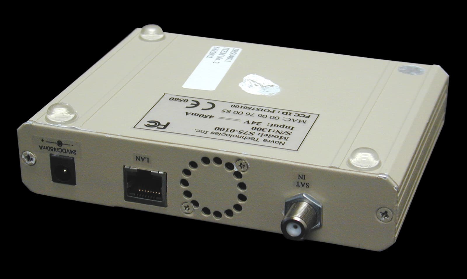
POIS750100
Jul 07, 2002Digital Satellite Receiver
Equipment Class
CXX - Communications Rcvr for use w/ licensed Tx and CBs