POIS750100Digital Satellite Receiver
Novra Technologies Inc.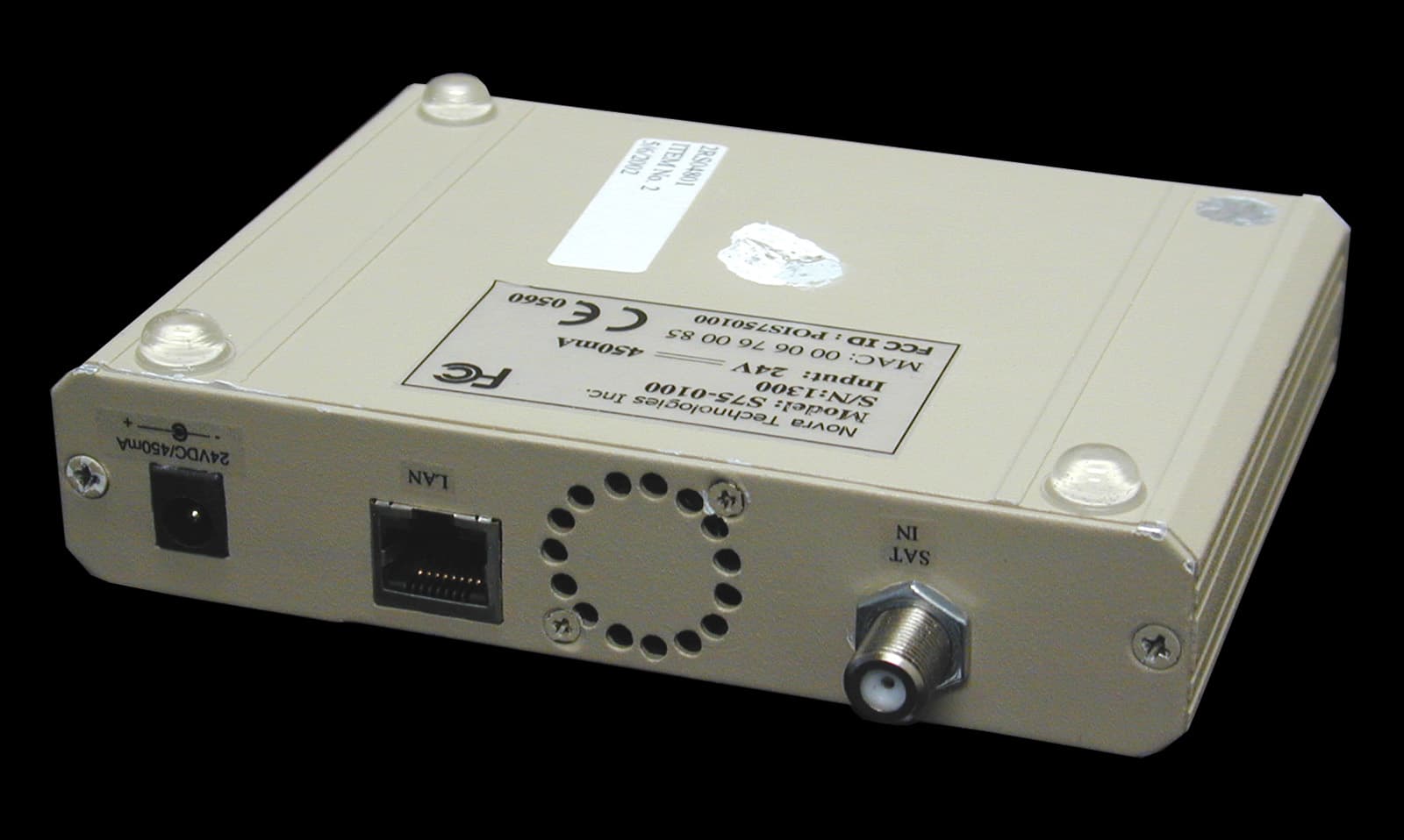
Click to zoom
Application Details
- Equipment Class
- CXX - Communications Rcvr for use w/ licensed Tx and CBs
- Date of Grant
- Jul 07, 2002
- Application Purpose
- Original Equipment
- Date of Application
- Jul 07, 2002
- Equipment Note
- Digital Satellite Receiver
- Frequency Range
- 950.00000000 - 960.00000000
- Company
- Novra Technologies Inc.
- Country
- Canada
Documents & Files
Document Text
Text extracted from the exhibit documents filed with the FCC. Open a document above to read the original.
Users Manual
Version 501D Confidential and Proprietary 1 of 24 Technologies Inc. novra TM Novra S75 Receiver User Manual Subject to change without notification Note: These Files have been optimized for printing. 24 Vdc (Center Power Supply Received THE RECEIVER PACKAGE (Cat 5 Crossover Cable) Installatio Disk Ethernet Packets to Control from PC S75 Receiver S75 directly controls and powers the LNB. S75 only receives L-Band from an existing network. OR Version 501D Confidential and Proprietary 2 of 24 Technologies Inc. novra TM Novra S75 Receiver, User Manual Subject to change without notification Document version: 501D ________________________________ Important- Please read this entire manual before installing or operating this product. ________________________________ Disclaimer While reasonable effort has been made in the preparation of this document to assure its accuracy, Novra Technologies Inc. assumes no responsibility for errors or omissions that may appear in this manual. Novra reserves the right to change the contents of this manual at any time without notice. Acknowledgements This product uses parts of the iMatix SFL, Copyright © 1991-2000 iMatix Corporation http://www.imatix.com This product incorporates the CPSLAPI Version 0.5.1 [Licensed under GNU LGPL V2 (GNU Library General Public License)] This product uses parts of the 1.3.0 release of the Common C++ class library which is licensed under the GNU General Public License with the exception that software linked with the Common C++ and other files to produce an executable, does not cause the resulting executable to be covered by the GNU General Public License. This product includes software developed by the Politecnico di Torino, and its contributors. Copyright © 2001 Novra Technologies Inc. All rights reserved. Information in this manual is subject to change without notice. No part of this manual may be reproduced or transmitted in any form, by photocopy, microfilm, xerography, or any other means, or incorporated into any information retrieval system, electronic or mechanical, for any purpose, without the express written permission of Novra Technologies Inc. Regulatory Compliance Novra Technologies Inc. is in the process of gaining FCC certification for this device. This certification is not currently complete. Version 501D Confidential and Proprietary 3 of 24 Technologies Inc. novra TM INDEX Page 1.0 CONVENTIONS 4 2.0 INTRODUCTION 5 2.1 Principle Of Operations 5 3.0 GETTING STARTED 6 3.1 Your Network Connection, is it Basic or Advanced? 6 3.11 Basic 6 3.12 Advanced 7 3.2 Required Information for Basic Connection 8 3.3 Required Information for Advanced Connection 9 4.0 SOFTWARE INSTALLATION on WINDOWS NT 4.0 or 2000 10 5.0 BASIC CONFIGURATION 12 6.0 ADVANCED CONFIGURATION 14 7.0 MANAGEMENT CONSOLE DETAILED DESCRIPTION 17 7.1 Status Tab 17 7.2 Drop Down Menus 18 8.0 SPECIFICATIONS 20 8.1 Receiver Characteristics 20 8.2 Minimum System Requirements 20 8.3 Supplied Equipment 21 APPENDIX 22 Terms, Definitions, and Tidbits of Information Version 501D Confidential and Proprietary 4 of 24 Technologies Inc. novra TM 1.0 CONVENTIONS This symbol means that there are more notes on this topic located in the Appendix. This area intentionally left blank NOTE: Information in this box will be Informative. CAUTION: This information will be quite important and should not be i gnored. Version 501D Confidential and Proprietary 5 of 24 Technologies Inc. novra TM 2.0 INTRODUCTION 2.1 Principles of Operation Somewhere in the world is a location that transmits your signal, along with many others, up to a satellite which turns around and transmits those signals back down to your location, and others. Your satellite dish catches all these signals, and the electronics at the dish converts them all into a group that travels down the cable to your S75 receiver. The S75 sifts through all the signals sent by the satellite looking for your signal (a DVB stream) and forwards to your computer the portion containing the signals you want. Your computer further dissects the signals and converts them into a format that is usable by other programs on your PC. The S75 Management Console is used to configure addresses, specify satellite tuning parameters and select DVB information streams (PIDS). Once configured, the S75 will retain its settings and continue to forward data transmitted to you by your service provider even after restarting the S75 or your PC. The S75 Receiver is meant to run in the background on your PC. In most cases, once the options have been set you will have no need to change them. This area intentionally left blank Version 501D Confidential and Proprietary 6 of 24 Technologies Inc. novra TM 3.0 GETTING STARTED 3.1 Your Network Connection, is it Basic or Advanced ? This step will determine what parts of the manual are relevant to your setup. 3.11 Basic In this arrangement, someone else has already dealt with the satellite dish issues and distributed the signals so all that is required of you, is a connection to a coax cable. This arrangement has no control of the LNB. If this is your setup, you have a BASIC connection. Please Proceed to Required Information for Basic Connections. 24 Vdc (Center +ve) Power Supply Received THE S75 RECEIVER PACKAGE (Cat 5 Crossover Cable) Installatio Disk Ethernet Packets to Control from PC S75 Receiver Version 501D Confidential and Proprietary 7 of 24 Technologies Inc. novra TM Your Network Connection, is it Basic or Advanced ? (Continued) 3.12 Advanced In this arrangement, the S75 is required to control and power the LNB at the satellite receiver dish. If this is your setup, you have an ADVANCED connection. Please Proceed to Required Information for Advanced Connections. 24 Vdc (Center Power Supply Received S50 directly and powers the THE RECEIVER PACKAGE (Cat 5 Crossover Cable) Installatio Disk Ethernet Packets to Control from PC S75 Receiver CAUTION: Nothing should be inserted between the S75 and the satellite dish except f…
Text truncated - open the document above for the full version.
Block Diagram
1100 - 330 St. Mary Avenue, Winnipeg, Manitoba, Canada R3C 3Z5 / Phone (204) 989-4724 / Fax (204) 989-4640 T e c h n o l o g i e s I n c. novra S75 Satellite Receiver Block Diagram Design Parameters Frequency range: 950.0 MHz. – 2150.0 MHz. Symbol rate: 1.0 MS/s – 45.0 MS/s Data rate: to 69.0 Mbps Sensitivity: -65.0 dBm to –25.0 dBm Input Return Loss - 10 db @ 75 Ω Operating voltage: 20-30VDC 450mA Down ConvertorDemodulatorDSP EEROM SPIEEPROM IIC Microcontroller Frequency Synthesizer Power Supply MAC/PHY Data Serializer 3.3VD 8 MHz 3.3VD 100 Mb/s Ethernet LAN 20-30 Volts DC 450mA Satellite Signal 950 to 2150 MHz VLNB 5VA 5VAP3V3N P3V3AGC 5VAP3V3A 3.3VD 80 MHz 3.3VD 1.6VD ANA1 25 MHz 1.6VD 5VA 3.3VD 3.3VA ANA1 P3V3N P3V3A P3V3ADC
Cover Letter(s)
FCC ID: POIS750100 Reply to TCB findings ----- Original Message ----- From: Curtis-Straus TCB To: Ruby Dulmage Sent: June 13, 2002 5:00 PM Subject: Novra FCC ID: POIS750100 Hi Ruby, We have the following issues after our review of the application: 1. Please supply a block diagram as one was not supplied. Attached. 2. The 15.21 statement is not in the manual. Added to the attached manual. 3. The device was tested with the antenna in port terminated in a highly shielded coax cable and 75 ohm termination. In actual use this would be terminated into an antenna which is inherently unshielded. Please provide an engineering justification for testing without the antenna or provide radiated emissions test data for the device with an antenna attached. The S75 Receiver does not directly connect to a radiating element but it connects to a down-converter (10.7-12.75GHz down to 950-2150MHz). Hypothetically, if the receiver were to radiate the full LO power, the radiated field strength at 3m would still be well within the limit. The following is the calculation supporting that claim: E^2/(Zo) = Pt*Gt/(4*pi*R^2) where E = electric field (V/m) Pt=LO power (W) ---> -77dBm (measured at 950 and 960 MHz at the output of the receiver) Zo=impedance of free space = 120*pi Gt= gain taken to be 1 R= distance from the radiating element = 3m Pt =-77dBm = 2e-11 W E=8.16 micro volts ---> Limit = 500 micro volts at 3m at 960MHz. 4. The FCC do not regulate receivers capable of tuning above 960MHz therefore testing should be conducted with the local oscillator set to the appropriate frequency for tuning to the 950-960MHz band. Please supply revised test data. The grant will only quote the 950 to 960 MHz band. Depending on approval of answer to question 3 above, test data may be OK as submitted. Please advise. TCB – Existing data acceptable. 5. CXX is not the correct equipment code. HID would be more appropriate. The S75 is not a TV receiver as it's output is Ethernet traffic. Other choices from the list that has been provided in form 731 are CYY or JBP. I'm not sure if JBP is available as a code anymore. Please advise. TCB – FCC advise that CXX is acceptable. Best regards Barry C. Quinlan Certification Manager Curtis-Straus TCB
ID Label/Location Info
bottom.jpg (1224x1040x24b jpeg)
Operational Description
Technical Information This Document is Confidential to Novra Technologies Inc. Theory of Operation The S75 is a DVB (Digital Video Broadcast) satellite receiver that will provide Internet and Multicast services to any computer with a 10/100 Mbps network interface. Satellite data rates up to 50Mbs can be delivered to a single computer or to a LAN. In addition to IP based data delivery, the S75 allows DVB pipes, DVB streams, and DVB data and Object carousels to be transferred onto an IP network. The S75 receiver has a tuning range of 950 - 2150MHz. It will receive a QPSK signal levels from the LNB (Low Noise Block) in the range of –65dBm to –25dBm at symbol rates between 1 and 45 Msps. Through the same ( F-type) port the receiver will also power the LNB with 18V. The S75 itself is power by 24V DC (supplied by AC/DC converter) S75 Receiver – Application Diagram content, Internet Uplink novra S75 Return channel DVB-S
Test Report
Master: PT15BBV Date: January 25, 2002 Test Report:2R04801.2 Applicant:Novra Technologies Inc. 100-330 St. Mary Ave. Winnipeg, Manitoba R3C 3Z5 Equipment Under Test (EUT):S75 Satellite Receiver In Accordance With:FCC 47 CFR Part 15, Subpart B: 1999 Class B Certification Tested By:Nemko Canada Inc. 303 River Road, R.R. 5 Ottawa, Ontario K1V 1H2 Authorized By: J. Harrington, RF Group Manager Date:17 May 2002 Total Number of Pages:19 Nemko Canada Inc.FCC 47 CFR PART 15, SUBPART B: 1999 CLASS B CERTIFICATION PROJECT NO.: 2R04801.2 EQUIPMENT: S75 Satellite Receiver Page 2 of 19 Table Of Contents Section 1. Summary of Test Results......................................................................................3 Section 2. Equipment Under Test.........................................................................................6 Section 3. Equipment Configuration....................................................................................8 Section 4. Conducted Emissions..........................................................................................10 Section 5. Radiated Emissions.............................................................................................13 Section 6. Sample Calculations............................................................................................16 Section 7. Block Diagrams...................................................................................................17 Section 8. Test Equipment List...........................................................................................19 Annex A Prescans For Engineering Evaluation Only..........................................................A1 Nemko Canada Inc.FCC 47 CFR PART 15, SUBPART B: 1999 CLASS B CERTIFICATION PROJECT NO.: 2R04801.2 EQUIPMENT: S75 Satellite Receiver Page 3 of 19 Section 1.Summary of Test Results General: All measurements are traceable to national standards. These tests were conducted on a sample of the equipment for the purpose of demonstrating compliance with FCC Part 15, Subpart B for Class B Digital Devices. These tests were conducted using measurement procedures of ANSI C63.4-1992. The equipment was tested for conducted emissions from 0.45 MHz to 30 MHz using a 50 microhenry line impedance stabilization network (L.I.S.N.) as described in ANSI C63.4-1992. Peripheral equipment was also operated through a 50 microhenry L.I.S.N. Abstract: Name Of TestPara. No.Results Conducted Emissions15.107Complied Radiated Emissions15.109Complied THIS TEST REPORT APPLIES ONLY TO THE ITEM(S) TESTED. Test Performed By: ________________________________Date: 17 May 2002 Daniel Hynes, EMC Specialist Nemko Canada Inc., a testing laboratory, is accredited by the Standards Council of Canada. The tests included in this report are within the scope of this accreditation. Nemko Canada Inc. authorizes the above named company to reproduce this report provided it is reproduced in its entirety and for use by the company’s employees only. Any use which a third party makes of this report, or any reliance on or decisions to be made based on it, are the responsibility of such third parties. Nemko Canada Inc. accepts no responsibility for damages, if any, suffered by any third party as a result of decisions made or actions based on this report. This report applies only to the items tested and does not constitute endorsement by the United States of America. Nemko Canada Inc.FCC 47 CFR PART 15, SUBPART B: 1999 CLASS B CERTIFICATION PROJECT NO.: 2R04801.2 EQUIPMENT: S75 Satellite Receiver Page 4 of 19 Measurement Uncertainty Accuracy of Measurement The measurement uncertainty was calculated using the methods described in NAMAS document NIS81 May 1994, with the confidence level of 95%. Radiated Measurements OATS #1 (A) 3 meter [UN9902B] ContributionDistributionUncertainty (+/-) Field Strength VariationRandom 0.2089 dBμV^2 Measurement EquipmentNormal 0.3275 dBμV^2 Measurement EquipmentRectangular 0.4167 dBμV^2 Total Combined Uncertainty 0.9762 dBμV^2 Expanded Uncertainty @ 95% Confidence = ±± 2.0013 dBμμV OATS #1 (B) 10 meter [UN9906B] ContributionDistributionUncertainty (+/-) Field Strength VariationRandom 0.1388 dBμV^2 Measurement EquipmentNormal 0.3275 dBμV^2 Measurement EquipmentRectangular 0.4167 dBμV^2 Total Combined Uncertainty 0.9694 dBμV^2 Expanded Uncertainty @ 95% Confidence = ±± 1.926 dBμμV OATS #2 (B) 3 meter [UN9912B] ContributionDistributionUncertainty (+/-) Field Strength VariationRandom 0.4516 dBμV^2 Measurement EquipmentNormal 0.3275 dBμV^2 Measurement EquipmentRectangular 0.4167 dBμV^2 Total Combined Uncertainty 1.0935 dBμV^2 Expanded Uncertainty @ 95% Confidence = ±± 2.2417 dBμμV Nemko Canada Inc.FCC 47 CFR PART 15, SUBPART B: 1999 CLASS B CERTIFICATION PROJECT NO.: 2R04801.2 EQUIPMENT: S75 Satellite Receiver Page 5 of 19 Radiated Measurements, continued OATS #2 (C) 10 meter [UN9917B] ContributionDistributionUncertainty (+/-) Field Strength VariationRandom 0.1211 dBμV^2 Measurement EquipmentNormal 0.3275 dBμV^2 Measurement EquipmentRectangular 0.4167 dBμV^2 Total Combined Uncertainty 0.9302 dBμV^2 Expanded Uncertainty @ 95% Confidence = ±± 1.9069 dBμμV Conducted Measurements Shielded Room #1 [UN9920] ContributionDistributionUncertainty (+/-) Amplitude VariationRandom 0.0400 dBμV^2 Measurement EquipmentNormal 0.7500 dBμV^2 Measurement EquipmentRectangular 0.2500 dBμV^2 Total Combined Uncertainty 1.0198 dBμV^2 Expanded Uncertainty @ 95% Confidence = ±± 2.0396 dBμμV Nemko Canada Inc.FCC 47 CFR PART 15, SUBPART B: 1999 CLASS B CERTIFICATION PROJECT NO.: 2R04801.2 EQUIPMENT: S75 Satellite Receiver Page 6 of 19 Section 2.Equipment Under Test Brand Name:Novra Manufacturer:Novra Technologies Inc. Model No.:S75-0100 Serial No.:1301 Date Received In Laboratory: May 6, 2002 Nemko Identification No.: Item #3 Production UnitPre-Production Unit Description of EUT The S75 is a DVB (Digital Video Broadcast) satellite receiver with a tuning frequency of 950- 2150MHz. Modificati…
Text truncated - open the document above for the full version.
Contact Information
Applicant
Nathan Jacob(Director, Network Devices)
Test Firm
Nemko Canada Inc.Stuart Beck
Technical Specifications
| # | Rule Parts | Frequency Range | Power Output |
|---|---|---|---|
| 1 | 15B | 950 MHz - 960 MHz | - |
Other Applications from Novra Technologies Inc.
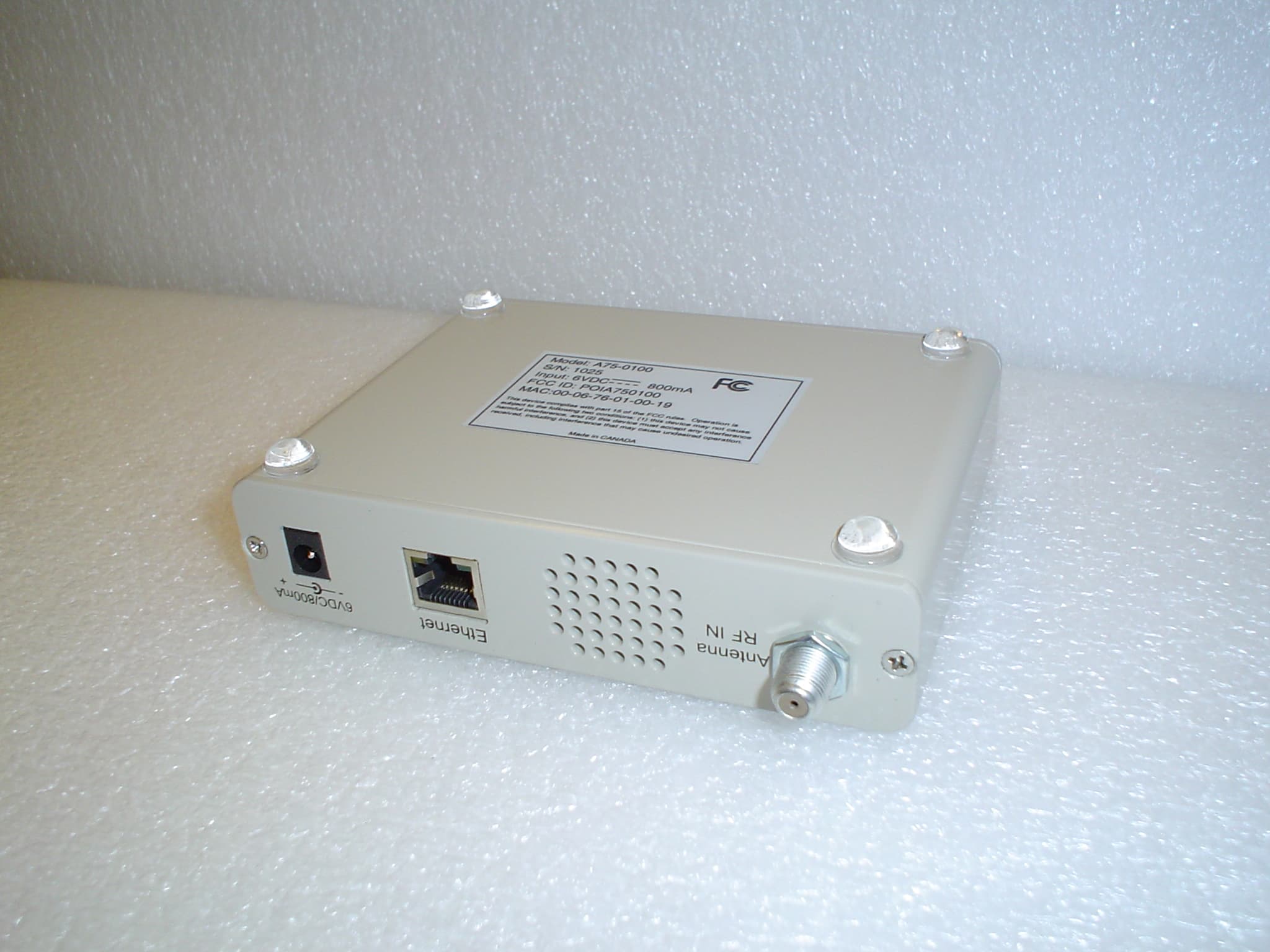
POIA750100
Jun 20, 2004Communications Receiver
Equipment Class
CXX - Communications Rcvr for use w/ licensed Tx and CBs