POM92386VoiceStream
IntriCon Corporation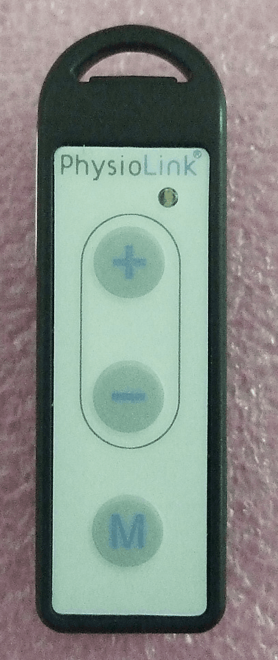
Click to zoom
Application Details
- Equipment Class
- DTS - Digital Transmission System
- Date of Grant
- Sep 06, 2012
- Application Purpose
- Original Equipment
- Date of Application
- Sep 06, 2012
- Equipment Note
- VoiceStream
- Frequency Range
- 2400.00000000 - 2483.50000000
- Company
- IntriCon Corporation
- Country
- United States
Documents & Files
Document Text
Text extracted from the exhibit documents filed with the FCC. Open a document above to read the original.
Users Manual
1 LUMEN 1000 & ACCESSORIES USER GUIDE 2 Device Summary Lumen 1000 is a BTE hearing aid that receives audio signal and converts into acoustic output. A rocker switch control provides the user interface input. In addition to providing volume control, the Up and Down keys of the rocker switch can be used to toggle between different pre-loaded audio programs, audio streaming being one of them. Lumen 1000 receives audio signals transmitted wirelessly from paired accessories (linkstream, voicestream and flexstream). The Li- Po battery in the unit is charged using a customized Lumen 1000 Charger device. Each device has a unique serial number. Linkstream is designed to pick up audio signal from a television and relaying it wirelessly to the hearing aid device. . The device is be powered by a 120-240V wall power adapter via a mini USB socket and picks up the TV audio through an audio cord connection to the TV audio output. It uses a high efficiency external antenna to allow link distances of 5 meters. An LED indicates It may need to have a function button and LED. It is also be used to program Lumen 1000 device when connected to a PC. Voicestream is designed to pick up nearby sounds through two internal microphones, amplifies those sounds, and converts them into a digital wireless transmission to the Lumen 1000 hearing aid. A membrane switch serves as a user interface for mode and volume control. The use of more than one microphone allows it to function in OMNI and DIRECTIONAL modes. MicroUSB cable is used to recharge the Li-Po battery. Typical use environments include restaurants, cars, meetings etc. Flexstream draws power from the host iPhone, iPod Touch, or iPad and sends audio and/or command information wirelessly to Lumen 1000. It will connect to the host via the 30 pin dock connector. The use of more than one microphone allows it to function in OMNI and DIRECTIONAL modes. Typical use scenarios include listening to iTunes player, cell phone calls, reloading Lumen 1000 firmware from a host app. 3 Lumen 1000 Charger will draw power from one AAA alkaline battery and or microUSB cable connected to a wall outlet. The charger has a nest to hold the Lumen 1000 hearing aid and the entire unit is small enough to go into a shirt or coat pocket or purse compartment. The device has a LED to indicate charging status. 4 Lumen 1000 Hearing Aid Lumen 1000 Device Illustration Device Description 1 Lumen 1000 Unit 2 Clear Tube System 3 Dome Shaped Earbud 4 Rocker Switch Program Switch Volume Control 5 Charging Contact Pins 6 Lasermarking Area Charging procedure and installation in charger Charger Description 5 Lumen 1000 Charger Device Illustration Device Description 1 Lumen 1000 Charger Unit 2 Cover Slide 3 LED Charge Indicator 4 Batter Door 5 MicroUSB Port 6 Dummy Lumen 1000 7 AAA Battery 8 MicroUSB Cable Charging with mUSB cable Charging with Battery 6 Lumen 1000 can be recharged about 5-8 times with one AAA battery. Installing Lumen 1000 into charger Charge Lumen 1000 fully before 1 st use. Typical charge time is about 2.5hrs. After charging is complete the red LED light on charger automatically goes OFF Note: Charger cover door can be closed only when Lumen 1000 with thin tube is inserted. Lumen 1000 with Earhook cannot be closed in charger. Lumen 1000 can be inserted only one way 7 Installing sound tube to Lumen 1000 Choose tip and length that fits best (most comfortable) or as recommended by audiologist Exact tube availability to be determined by the customer Verify Lumen 1000 is charged Press rocker switch to hear beep ?? or pair with accessory ?? Using Lumen 1000 Wearing Lumen 1000 8 Ear Tube and Tip Replacing ear tube & tip Your ear tube & tip will come connected. For optimal performance, replace ear tube & tip every three months. Removing ear tube & tip from device: Grasp the “device end” of the ear tube; gently turn ~90 degrees and pull to remove the ear tube from the device. Attaching ear tube & tip to device: Gently push the “device end” of the ear tube onto the device until it snaps into position. Cleaning ear tube & tip Between replacements, you’ll need to clean the ear tube & tip with a cleaning wire, typically once a week. Remove the ear tube & tip from device. Thread the cleaning wire through the ear tube, starting at the “device end,” until it comes out at the “ear tip end,” then pull the cleaning wire all the way through. Be sure to wipe off the wire before the next cleaning. Note: Ensure the wire goes through the ear tube in only one direction, from “device end” to “ear tip end.” Do not reverse the wire back through the ear tube. Clean the ear tip with a dry cloth 9 Removing ear hook from device: Grasp the “device end” of the ear hook; gently turn ~90 degrees and pull to remove the ear hook from the device. Attaching ear hook to device: Gently push the “device end” of the ear hook onto the device until it snaps into position. Rocker switch functions Rocker Switch Presses Function Short up Volume up (default) or program up (configurable in MT) Short down Volume down (default) or program down (configurable in MT) Medium Up (default 3s, but configurable in MT) volume up or program up (default) (configurable in MT) Medium Down (default 3s, but configurable in MT) volume down or program down (default) (configurable in MT) Long Down with power on (default 5s, but will be configurable in MT) Shutdown Long Down with power off (default 5s, but will be configurable in MT) Wakeup Extra Long Down with power off (default 10s, but will be configurable in MT) Wakeup and enter pairing mode a. Telephones Using with telephones and cellular phones i. Hold the phone handset as you normally would. Move the handset up slightly to find the position that sounds best to you. If you encounter whistling (feedback), tilt the phone handset at an angle until the whistling stops. b. Cellular phones i. Lumen 1000 is designed to comply with the most stringent Standards of International Electromagnetic Compatibility. Howe…
Text truncated - open the document above for the full version.
External Photos
4/26/20121 VOICESTREAM EXTERNAL PHOTOS
Internal Photos
4/26/20121 VOICESTREAM INTERNAL PHOTOS
RF Exposure Info
EMC Report No: 100658121MIN-004B FCC ID: POM92386 Page 29 of 45 3.5 RF Exposure Compliance The maximum measured power, P is -2.8dBm The antenna gain, G is 1.3dBi The maximum EIRP power = P + G ERP = -2.8 + 1.3 = -1.5dBm, or 0.708mW or 0.00071W The limits for Maximum Permissible Exposure (MPE) for transmitter operating at 2.4Hz, MPE is 1mW/cm 2 , or 10W/m 2 The Power Density, S is related to EIRP with the equation: S = EIRP / 4 πD 2 , where D is the safe separation distance and = 0.2m, or 20cm S = 0.708 / 4π20 2 , S = 0.00014mW/cm 2, , or below the Maximum Permissible Exposure (MPE)
Test Report
TEST REPORT Report Number: 100658121MIN-004B Project Number: G100658121 Testing performed on the VoiceStream / Companion Mic FCC ID: POM92386 to 47 CFR Part 15. 247:2010 RSS- 210, Issue 8, 2010 47 CFR, Part 15:2009, §15.107 and §15.109, Class B For IntriCon Corporation Test Performed by: Test Authorized by: Intertek Testing Services NA, Inc. 7250 Hudson Blvd., Suite 100 Oakdale, MN 55128 USA IntriCon Corporation 1260 Red Fox Road Arden Hills, MN 55112-6944, USA Prepared by: Date: September 4, 2012 Simon Khazon Reviewed by: Date: September 4, 2012 Uri Specotr This report is for the exclusive use of Intertek's Client and is provided pursuant to the agreement between Intertek and its Client. Intertek's responsibility and liability are limited to the terms and conditions of the agreement. Intertek assumes no liability to any party, other than to the Client in accordance with the agreement, for any loss, expense or damage occasioned by the use of this report. Only the Client is authorized to copy or distribute this report and then only in its entirety. Any use of the Intertek name or one of its marks for the sale or advertisement of the tested material, product or service must first be approved in writing by Intertek. The observations and test results in this report are relevant only to the sample tested. This report by itself does not imply that the material, product, or service is or has ever been under an Intertek certification program. This report must not be used to claim product endorsement by A2LA, NIST nor any other agency of the U.S. Government. EMC Report No: 100658121MIN-004B FCC ID: POM92386 Page 2 of 45 TABLE OF CONTENTS 1.0 GENERAL DESCRIPTION.......................................................................................................... 3 1.1 Product Description; Test Facility ....................................................................................... 4 1.3 Environmental conditions.................................................................................................... 5 1.4 Measurement uncertainty ................................................................................................... 6 1.5 Field Strength Calculation................................................................................................... 6 2.0 TEST SUMMARY.......................................................................................................................... 7 3.0 TEST CONDITIONS AND RESULTS........................................................................................ 8 3.1 Maximum peak output power.............................................................................................. 8 3.2 6dB bandwidth of the digital modulation........................................................................... 10 3.3 Power spectral density ...................................................................................................... 14 3.4 Radiated spurious emissions............................................................................................ 15 3.5 RF Exposure Compliance ................................................................................................. 29 3.6 Transmitter power line conducted emissions ................................................................... 30 3.7 Receiver/digital device radiated emissions....................................................................... 33 3.8 Digital device conducted emissions.................................................................................. 42 4.0 TEST EQUIPMENT..................................................................................................................... 45 EMC Report No: 100658121MIN-004B FCC ID: POM92386 Page 3 of 45 1.0 GENERAL DESCRIPTION Model: VoiceStream Type of EUT: Companion Microphone FCC ID: POM92386 Related Submittal(s) Grants: None Company: IntriCon Corporation. Customer: Mr. Vijay Sundermurthy Address: 1260 Red Fox Road Arden Hills, MN 55112-6944, USA Phone: (651) 604-9534 Fax: (612) 636-8944 e-mail: [email protected] Test Standards: 47 CFR, Part 15:2010, §15.247 RSS–210, Issue 8, 20010 RSS-Gen, Issue 3, 2010 47 CFR, Part 15:2010, §15.107 and §15.109, Class B ICES-003, Issue 4:2004 Other Type of radio: Stand -alone Module Hybrid Date Sample Submitted: March 2, 2012 Test Work Started: March 2, 2012 Test Work Completed: March 20, 2012 Test Sample Conditions: Damaged Poor (Usable) Good EMC Report No: 100658121MIN-004B FCC ID: POM92386 Page 4 of 45 1.1 Product Description; Test Facility Product Description: Transceiver Transmitter Type: FHSS Digital Modulation WiFi Blue Tooth Operating Frequency Range(s): Range From 2400 to 2483.4 MHz Number of Channels: 80 Modulation: FSK Antenna(s) Info: Type Integral Gain 1.3dBi Antenna Installation: User Professional Factory Transmitter power configuration: Internal battery External power source 120VAC 230VAC 400VAC VDC Other: Amp. 50Hz 60Hz Special Test Arrangement: Testing was performed on the EUT with fully charged internal battery Test Facility Accreditation: A2LA (Certificate No. 1427.01) Test Methodology: Measurements performed according to the procedures in ANSI C63.10- 2009 and FCC DTS Measurement Guide EMC Report No: 100658121MIN-004B FCC ID: POM92386 Page 5 of 45 1.2 EUT Configuration The equipment under test was operated during the measurement under the following conditions: - Standby - Continuous transmissions (modulated signal) - Continuous transmissions (un-modulated signal) - Continuous receiving - Test program (customer specific) - Operating modes of the EUT: No. Description 1 Test was performed at low channel of 2402MHz, middle channel of 2441MHz, and upper channel of 2481MHz. 2 Standby / Receiving mode 3 Charging mode EUT was powered at AC/DC Charger manufacturing by Tenwel, model TS21-500 500U Cables: No. Type Length Designation Note 1 Shielded, USB 1.0 m DC Power Support equipment/Services: No. Item Description None 1.3 Envir…
Text truncated - open the document above for the full version.
Test Setup Photos
Test Setup Photos
Contact Information
Applicant
Vijay Sundermurthy
Technical Contact
IntriCon CorporationOleg Mosesov
[email protected]6125582600
1260 Red Fox Road · Arden Hill, Minnesota · United States
Non-Technical Contact
IntriCon CorporationChris Conger
[email protected]6516049577
Test Firm
Intertek Testing Services NA, Inc.Andrew Waytulonis
Technical Specifications
| # | Rule Parts | Frequency Range | Power Output |
|---|---|---|---|
| 1 | 15C | 2.40 GHz - 2.48 GHz | 600.00 µW |
Other Applications from IntriCon Corporation
POM93047
Aug 24, 2015Charging Linkstream
Equipment Class
DTS - Digital Transmission System
POMRX92369
Sep 06, 2012Sirona ECG Recorder
Equipment Class
DXT - Part 15 Low Power Transceiver, Rx Verified
POM92482
Sep 06, 2012LinkStream
Equipment Class
DTS - Digital Transmission System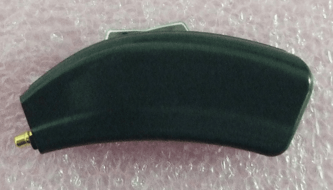
POMRX92480
Sep 06, 2012Lumen 1000 / Earpiece
Equipment Class
DXT - Part 15 Low Power Transceiver, Rx Verified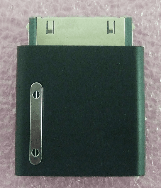
POM92365
Sep 05, 2012FlexStream
Equipment Class
DTS - Digital Transmission System