POM93047Charging Linkstream
IntriCon Corporation
Click to zoom
Application Details
- Equipment Class
- DTS - Digital Transmission System
- Date of Grant
- Aug 24, 2015
- Application Purpose
- Original Equipment
- Date of Application
- Aug 24, 2015
- Equipment Note
- Charging Linkstream
- Frequency Range
- 2402.00000000 - 2481.00000000
- Company
- IntriCon Corporation
- Country
- United States
Documents & Files
Document Text
Text extracted from the exhibit documents filed with the FCC. Open a document above to read the original.
Users Manual
Quick Start Guide 1 22602 Rev B LUMEN 1000 PSAP & CHARGING TV STREAMER Lumen 1000 PSAP Parts ..........................................3 Charging TV Streamer Parts ....................................4 Charging TV Streamer Setup ................................4-7 Lumen 1000: Assembly and Charging ....................8 Lumen 1000: Positioning on the Ear ......................9 Charging TV Streamer: Device Commands .........10 Lumen 1000: Rocker Switch Functions ................11 Additional Information ...........................................12 2 Table of Contents 22602 Rev B 3 Parts Included a.2 Lumen 1000 PSAP Devices b.6Sound Tubes (3 Left, 3 Right) c.6Dome Tips (2 Small, 2 Medium, 2 Large) a c 22602 Rev B Lumen 1000 PSAP Parts (Personal Sound Amplification Product) Tip Tip Base MediumLarge Small Lumen 1000 PSAP Devices Charging TV Streamer Parts Parts Included a.1 Charging TV Streamer b.1 Power Plug c.1 Mini USB to USB Cable a.1 Audio Cable b.1 RCA to female audio Adapter a b c Power LED Indicator (Blue) (M) Mode Button d Antenna e 4 Charging LED Indicator (RED) 22602 Rev B Mini USB to USB Cable Audio Cable Charging TV Streamer Power Plug RCA to female audio Adapter Charging LED Indicator (Red) Charging TV Streamer : Set Up Connecting Charging TV Streamer 1.Raise antenna to vertical position and insert Mini USB plug into the back of the Charging TV Streamer. 2.Attach the USB end of the cable to the Power Plug. 3.Insert the Power Plug into an electrical outlet. 4.Insert one end of the audio cable into the Charging TV Streamer. 5.Connect the remaining end of the audio cable to the desired audio source (TV, computer or music player). See following pages for more details. Tip:Your Charging TV Streamer will work best when the antenna is positioned vertically. 5 5. Tip: TheCharging TV Streamer powerLED will light up Solid blue when the Mini USB cable is connected to a power source. 22602 Rev B Tip: When outside of the Charging TV Streamer range (16 feet), the Lumen 1000 automatically switches to the PSAP mode. USB Mini USB Audio Cable Antenna Charging TV Streamer: Set Up –Connect to TV Headphone Jack 1.Locate headphone jack on the front, side or back of your TV. It will be identified by a headphone icon label, similar to the diagram shown. 2. Insert Audio Cable into TV headphone jack Audio Output Jacks 1.Locate audio output jacks on the front, side or back of your TV. They will look similar to the diagramshown. (See your specific products user manual for more information) 2.Insert the red RCA adapter into the red (R) jack. Insert the white RCA adapter into the white (L) jack. 3. Insert the audio cable from the Charging TV Streamer into the female audio jack on the opposite end of the RCA cable. 622602 Rev B Charging TV Streamer: Set Up –Connect to TV Computer Headphone Jack 1.Locate headphone jack on the front, side or back of your computer. It will be identified by a headphone icon label, similar to the diagram shown. 2. Insert Audio Cable into the computer headphone jack A/V Receiver Audio Output Jacks 1.Locate audio output jacks on the front, side or back of your A/V Receiver. They will look similar to the diagram shown. (See your specific products user manual for more information) 2.Insert the red RCA adapter into the red (R) jack. Insert the white RCA adapter into the white (L) jack. 3. Insert the audio cable from the Charging TV Streamer into the female audio jack on the opposite end of the RCA cable. Tip: TheTV audio will be muted if the headphone jack is used. Use the RCA cable connection to hear audio from the TV speakers and on your Lumen 1000 devices. 722602 Rev B 2. 3. Assembling the Lumen 1000 1.Choose left and right Sound Tube 2.Attach Dome Tip to Sound Tube. Choose a small or medium Dome Tip based on your personal comfort. 3.Snap base of Sound Tube assembly to nipple on earpiece. Lumen 1000: Assembly and Charging Charging the Lumen 1000 1.Insert body of the Lumen 1000 into the charging slot of the Charging TV Streamer. The Lumen 1000 must be turned off prior to charging. 2.The Sound Tube will remain hanging on the Antenna side. 8 Note: Your Lumen 1000 needs to be fully charged prior to 1st use. A full charge takes approximately 1 hour. 1. 2. Tip: The corresponding red LED on the Charging TV Streamer will turn on indicating the Lumen 1000 in that position is charging. The LED will turn off when the device is fully charged. 1. 22602 Rev B Note: Turn off the Charging TV Streamer(blue LED off) during Lumen 1000 charging Note: Turn off Charging TV Streamerto listen in PSAP mode only Lumen 1000: Positioning on the Ear Instructions for wearing 1.Place listening device over ear. 2.Insert Dome Tip into ear canal. 3.Tuck Retention Loop along bottom of ear cavity. 1.2.3. 922602 Rev B Charging TV Streamer: Device Commands FunctionButtonLED Charging TV StreamerONPressbuttonLight continuously shines solid blue Charging TV Streamer OFFPress buttonLight turns off Charging TV Streamer Device Commands Using your Charging TV Streamer 1.Wear and turn ON Lumen 1000. 2.Refer to Device Commands table below for the operating modes 1022602 Rev B Note: Make sure Lumen 1000 and charging TV Streamer is both ON to hear streaming audio Lumen 1000: Rocker Switch Functions CommandUser ActionAudible PromptSays TurnON Whenin OFF mode, Press rocker down until an audible response is heard “Battery” followed by “Low”, “One”, “Two”, “Three”, or “Four” dependent on battery level Turn OFF Press rocker down until an audible response is heard “Off” Volume UPBriefly pressrocker up None.Audible beep when volume reaches maximum range Volume DOWN Briefly pressrocker down None.Audible beep when volume reaches minimum range Low BatteryContinuous use“Battery low” at end of battery life 1122602 Rev B Additional Information 12 The Lumen 1000 battery life is about 4 hours when streaming continuously and 15 hours in PSAP mode. Charging TV Streamer range is approximately 16 feet. The Lumen 1000 automatically switches from …
Text truncated - open the document above for the full version.
External Photos
8/5/20151 CHARGING LINKSTREAM EXTERNAL PHOTOS
ID Label/Location Info
LOCATION OF LASERMARKED FCC ID 32375
Internal Photos
8/5/20151 CHARGING LINKSTREAM INTERNAL PHOTOS
RF Exposure Info
EMC Report No: 102155638MIN-001 FCC ID: POM93047 Page 51 of 63 3.6 RF Exposure Compliance The maximum measured power, P is 5.53dBm The antenna gain, G is 2.0dBi The maximum EIRP power = P + G EIRP = 5.53+ 2.0 = 7.53dBm, or 5.66mW or 0.00566W The limits for Maximum Permissible Exposure (MPE) for transmitter operating at 2.4Hz, MPE is 1mW/cm 2 , or 10W/m 2 The Power Density, S is related to EIRP with the equation: S = EIRP / 4πD 2 , where D is the safe separation distance and = 0.2m, or 20cm S = 5.66 / 4π20 2 , S = 0.001126mW/cm 2, , or below the Maximum Permissible Exposure (MPE)
Test Report
TEST REPORT Report Number: 102155638MIN-001 Project Number: G102155638 Testing performed on the Model: 93047 FCC ID: POM93047 to 47 CFR Part 15. 247:2015 47 CFR, Part 15:2015, §15.107 and §15.109, Class B For IntriCon Corporation Test Performed by: Test Authorized by: Intertek Testing Services NA, Inc. 7250 Hudson Blvd., Suite 100 Oakdale, MN 55128 USA IntriCon Corporation 1260 Red Fox Road Arden Hills, MN 55112-6944, USA Prepared by: Uri Spector Reviewed by: Date of issue: July 22, 2015 Simon Khazon This report is for the exclusive use of Intertek's Client and is provided pursuant to the agreement between Intertek and its Client. Intertek's responsibility and liability are limited to the terms and conditions of the agreement. Intertek assumes no liability to any party, other than to the Client in accordance with the agreement, for any loss, expense or damage occasioned by the use of this report. Only the Client is authorized to permit copying or distribution of this report and then only in its entirety. Any use of the Intertek name or one of its marks for the sale or advertisement of the tested material, product or service must first be approved in writing by Intertek. The observations and test results in this report are relevant only to the sample tested. This report by itself does not imply that the material, product, or service is or has ever been under an Intertek certification program. EMC Report No: 102155638MIN-001 FCC ID: POM93047 Page 2 of 63 TABLE OF CONTENTS 1.0 GENERAL DESCRIPTION.......................................................................................................... 3 1.1 Product Description; Test Facility ....................................................................................... 4 1.3 Environmental conditions.................................................................................................... 5 1.4 Measurement uncertainty ................................................................................................... 6 1.5 Field Strength Calculation................................................................................................... 6 2.0 TEST SUMMARY.......................................................................................................................... 7 3.0 TEST CONDITIONS AND RESULTS........................................................................................ 8 3.1 6dB modulated DTS bandwidth .......................................................................................... 8 3.2 Maximum peak output power............................................................................................ 12 3.3 Power spectral density...................................................................................................... 16 3.4 Antenna conducted spurious emissions ........................................................................... 20 3.5 Radiated spurious emissions............................................................................................ 29 3.5.1 Band-edge measurements................................................................................................ 46 3.6 RF Exposure Compliance ................................................................................................. 51 3.7 Transmitter power line conducted emissions ................................................................... 52 3.8 Receiver/digital device radiated emissions....................................................................... 55 3.9 Digital device conducted emissions.................................................................................. 59 4.0 TEST EQUIPMENT..................................................................................................................... 62 5.0 REVISION HISTORY.................................................................................................................. 63 EMC Report No: 102155638MIN-001 FCC ID: POM93047 Page 3 of 63 1.0 GENERAL DESCRIPTION Model: 93047 Type of EUT: Charging Linkstream with Power Amplifier Intertek Sample ID: MIN1507101025-004 FCC ID: POM93047 Related Submittal(s) Grants: None Company: IntriCon Corporation Customer: Mr. Vijay Sundermurthy Address: 1260 Red Fox Road Arden Hills, MN 55112-6944, USA Phone: (651) 604-9534 Fax: (612) 636-8944 e-mail: [email protected] Test Standards: 47 CFR, Part 15:2015, §15.247 RSS–247, Issue 1, 2015 RSS-Gen, Issue 4, 2014 47 CFR, Part 15:2015, §15.107 and §15.109, Class B ICES-003, Issue 5:2012 Other Type of radio: Stand -alone Module Hybrid Date Sample Submitted: July 9, 2015 Test Work Started: July 9, 2015 Test Work Completed: July 20, 2015 Test Sample Conditions: Damaged Poor (Usable) Good EMC Report No: 102155638MIN-001 FCC ID: POM93047 Page 4 of 63 1.1 Product Description; Test Facility Product Description: Transmitter Transmitter Type: FHSS Digital Modulation WiFi Blue Tooth Operating Frequency Range(s): Range 1. From 2402 to 2481MHz Number of Channels: 80 Modulation: FSK Antenna(s) Info: Integral Gain 2.0dBi Antenna Installation: User Professional Factory Transmitter power configuration: Internal battery External power source 120VAC 230VAC 400VAC VDC Other: 0.15 Amp. 50Hz 60Hz Special Test Arrangement: None Test Facility Accreditation: A2LA (Certificate No. 1427.01) Test Methodology: Measurements performed according to the procedures in ANSI C63.10- 2013 and FCC 558074 D01 DTS Measurement Guidance EMC Report No: 102155638MIN-001 FCC ID: POM93047 Page 5 of 63 1.2 EUT Configuration The equipment under test was operated during the measurement under the following conditions: - Standby - Continuous transmissions (modulated signal) - Continuous transmissions (un-modulated signal) - Continuous receiving - Test program (customer specific) - See below Operating modes of the EUT: No. Description 1 Test was performed at low channel 2402MHz, middle channel 2441MHz, and upper channel 2481MHz. 2 Standby mode for digital portion 3…
Text truncated - open the document above for the full version.
Test Setup Photos
Test Setup Photos
Contact Information
Applicant
Vijay Sundermurthy
Technical Contact
IntriConOleg Mosesov
[email protected]6516049531
1260 Red Fox Road · Arden Hills, Minnesota · United States
Non-Technical Contact
IntriCon CorporationZachary Pope
[email protected]6516049527
Test Firm
Intertek Testing Services NA, Inc.Andrew Waytulonis
Technical Specifications
| # | Rule Parts | Frequency Range | Power Output |
|---|---|---|---|
| 1 | 15C | 2.40 GHz - 2.48 GHz | 4.00 mW |
Other Applications from IntriCon Corporation
POMRX92369
Sep 06, 2012Sirona ECG Recorder
Equipment Class
DXT - Part 15 Low Power Transceiver, Rx Verified
POM92386
Sep 06, 2012VoiceStream
Equipment Class
DTS - Digital Transmission System
POM92482
Sep 06, 2012LinkStream
Equipment Class
DTS - Digital Transmission System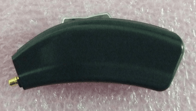
POMRX92480
Sep 06, 2012Lumen 1000 / Earpiece
Equipment Class
DXT - Part 15 Low Power Transceiver, Rx Verified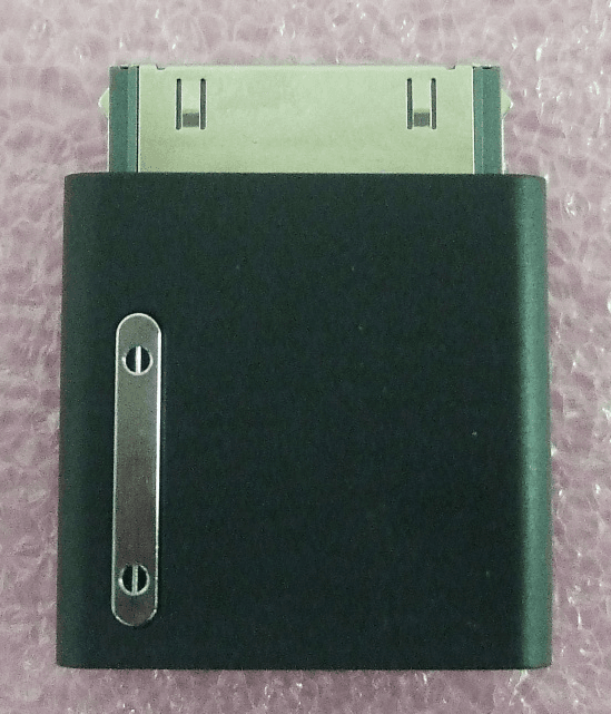
POM92365
Sep 05, 2012FlexStream
Equipment Class
DTS - Digital Transmission System