PP2M7886WWIRELESS OPTICAL MOUSE
Shenzhen Rapoo Technology Co., Ltd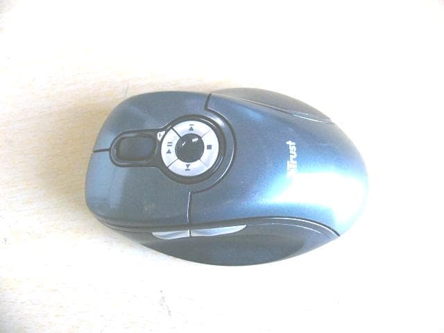
Click to zoom
Application Details
- Equipment Class
- DXX - Part 15 Low Power Communication Device Transmitter
- Date of Grant
- Aug 15, 2007
- Application Purpose
- Original Equipment
- Date of Application
- Aug 15, 2007
- Equipment Note
- WIRELESS OPTICAL MOUSE
- Frequency Range
- 27.04500000 - 27.04500000
- Country
- China
Documents & Files
Document Text
Text extracted from the exhibit documents filed with the FCC. Open a document above to read the original.
Users Manual
Note: This device complies with Part 15 of the FCC rules. Operation is subject to the following two conditions: (1) This device may not cause harmful interference, and (2) This device must accept any interference received, including i nterference that may cause undesired operation. Caution: The manufacturer is not responsible for any radio or TV interference caused by unauthorized modifications to this equipment. Such modifications could void the user authority to operate the equipment.
Users Manual
UK WIRELESS OPTICAL MULTIMEDIA DESKSET DS-3250 DE FR IT ES PL NL PT GR DK SE HU CZ FI NO TR RU User’s manual Version 1.0 SK USER’S MANUAL Installation 1 2 A B C D E G F H 4 3 USER’S MANUAL USER’S 1 MANUAL Product information A: Internet Buttons Browser back Browser forward Search Browser reload Browser stop C: Launch/special Buttons Start Internet Browser Start E-mail program Favorites Launch Windows default Mediaplayer* Insert special characters D: System Buttons Power Sleep / Standby Wake up My computer* Calculator* B: Media Keys Play / Pause Previous track Next track Stop Volume down direction Volume up direction Mute Media Center Functions Previous Screen Channel Up Channel Down OK E: USB Receiver F: Mouse 4 th and 5 th buttons (Browser Back/ Forward ) G: Scrollwheel with on frontside Battery empty LED H: Multimedia buttons (functions: see table B) * Driver from Trust website needed to support function in Windows 2000 UK Installation 1 Open battery compartments on bottom sides of mouse and keyboard and place the 4 batteries. 2 Connect USB Transmitter to PC and wait until automatic installation has completed. (Answer any question Windows asks with Allow, Continue, Next, OK or Yes) 3 Push connect button on USB Transmitter. 4 Push connect button on bottom side of Keyboard and finally connect button on bottom side of mouse. USER’S MANUAL 2 Note Multimedia and Office keys • Launch keys will start the default internet browser, E-mail program and Mediaplayer installed on your PC. Configure default programs: XP: Start Æ Control PanelÆ Add/Remove Programs Æ Set Program Access and Defaults. Vista: Start Æ Control PanelÆDefault ProgramsÆSet programs access and computer defaultsÆ Custom • The multimedia keys also work with other media player software like Itunes. • 4th and 5 th Mouse button only work in games that support standard 5 button mice. Special characters • The keyboard country layout settings in Windows should correspond with the keyboard layout of your Trust keyboard. Layout of the Trust keyboard is specified by a sticker on the Box. To set the keyboard Layout in Windows: Go to: Start Æ Control Panel (classic view) Æ Regional and Language Options Æ Languages Æ Details (Vista: “Change Keyboards”) • The Alt Gr key gives access to special characters like the € sign. An overview of the special characters per country is available at www.trust.com/keyboardlayout. Performance • Maximum Wireless working distance is around 2,5 meter. • Reduced wireless performance can be caused by: - (Metal) objects close to or between transmitter and keyboard Æ Remove objects. - Other wireless devices close by Æ Remove devices or reconnect USB transmitter to get different communication ID. - Empty batteries Æ Replace batteries. • Mouse will have reduced tracking performance on very shiny or transparent surfaces. Energy • Battery lifetime: Mouse: +/- 130 hours. Keyboard: +/- 4500 hours. • The mouse will enter sleep mode after 10 minutes of inactivity, but will respond immediately after pressing a button. • When mouse batteries are empty, the battery empty LED in front of the scroll wheel will light. • Never recharge the batteries provided and never throw them onto a fire. • Observe local regulations when disposing of batteries. Safety instructions • Do not open or repair this device. • Do not use the device in a damp environment. Clean the device with a dry cloth. USER’S MANUAL 3 See www.trust.com/15052 for up-to-date FAQs, Windows 2000 driver and instruction manuals. For extensive service, register at www.trust.com/register. UK • This device meets the essential requirements and other relevant conditions of the applicable European directives. The Declaration of Conformity (DoC) is available at www.trust.com/15052/ce. Wireless • This class 1 wireless device works at a frequency of 27 MHz It meets the essential requirements and other relevant conditions of R&TTE Directive 1999/5/EC and can be used in the following countries: all EU countries, as well as RU, TR, NO and HU. There are no limitations per channel for the above- mentioned countries. See www.trust.com/15052 for an updated list of the countries where the use of this device is permitted. • There may be restrictions for the use of this device outside of the EU. If this device is used outside of the EU, check whether this device meets the local regulations. Frequency: 27.045 ~ 27.145MHz Bandwidth: approx. 6 KHz; Power: 0,5 mW. • Be careful when using wireless devices if you have a pacemaker or are dependent on other life- saving, sensitive electronic equipment, because this device transmits radio signals. • If possible, dispose of the device at a recycling centre. Do not dispose of the device with the household waste. Warranty & copyright • This device has a two-year product warranty which is valid from the date of purchase. See www.trust.com/warranty for more information. • It is forbidden to reproduce any part of this instruction manual without the permission of Trust International B.V. BENUTZ 1 ERHANDBUCH Produktinformationen A: Internettasten Zurück Vorwärts Suchen Aktualisieren Abbrechen C: Start-/Sondertasten Internetbrowser starten E-Mail-Programm starten Favoriten Standard-Mediaplayer* von Windows starten Sonderzeichen einfügen D: Systemtasten Ein-/Ausschalten Ruhezustand/Standby Aktivieren Arbeitsplatz* Rechner B: Medientasten Abspielen/Pause Vorhergehende Nummer Nächste Nummer Abbrechen Leiser Lauter Stummschaltung Media-Center-Funktionen Vorherige Anzeige Vorheriger Kanal Nächster Kanal OK E: USB-Empfänger F: 4. und 5. Maustaste (Zurück/Vorwärts im Browser) G: Scrollrad mit Batteriestandanzeige auf der Vorderseite H: Multimedia-Tasten (für die Funktionen siehe Tabelle B) * Zur Unterstützung dieser Funktion in Windows 2000 brauchen Sie einen Treiber von der Trust- Website. DE Installation 1 Öffnen Sie die Batteriefächer auf der Unterseite der Maus und der Tastatur und legen Sie die 4 Batterien ein. 2 Schließen Sie den USB-Sender an den PC an und …
Text truncated - open the document above for the full version.
External Photos
EUT top view EUT bottom view
ID Label/Location Info
This device complies with Part 15 of the FCC Rules. Operation is subject to the following two conditions: (1) this device may not cause harmful interference, and (2) this device must accept any interference received, including interference that may cause undesired operation. Proposed Label Location on EUT EUT Bottom View/Proposed FCC ID Label Location FCC ID: PP2M7886W
Internal Photos
EUT inside whole view Main board component side Main board solder side
Operational Description
circuit description: X3 the 27.045 crystal oscillator driver the base of U1 the final/buffer amplifier into the same base (U1) is the modulation provided by U1 , the output of U1 has the matching network consisting of C4 ,C5, C9 and the C4,C5 that limit the harmonic content and effect the proper coupling of the antenna to the output stage. Antenna ground and power source The antenna is extension, there is no external ground connection .the ground is only that of the printed circuit board. electric current is supplied by 2*AAA batteries.
Schematics
1 2 34 ABCD 4 3 2 1 D CBA OSC1 1 SPI_SEL 2 VSS 3 OSC2 4 IR_MECH_SEL 5 VDD 6 F7632_SEL 7 RBUT 8 MBUT 9 LBUT 10 RFOUT 11 ORFIN0 12 ORFIN1 13 ORFO 14 TXD 15 PD 16 scan_in(0) 17 scan_in(1) 18 XIR 19 FOSC1 20 FOSC2 21 Z1IN 22 Z2IN 23 SDIO 24 SCLK 25 VSS 26 X2IN 27 scan_out(0) 28 X1IN 29 scan_out(1) 30 Y1IN 31 Y2IN 32 scan_out(2) 33 TXCB 34 BBUT 35 FBUT 36 SVDIN 37 DCVR 38 VL 39 VL_NM 40 U1 PM6227-D R110M C822PC122P X276.8K S3SWLS2SWMS1SWR C9 100P L21.8UH C5 150P C4 20P C6 0.1U C733P X3 27.045M C1533P C12 5p R6 2.2M X5 2M C2047P C2147P VCC S6SWID S5SWBS4SWF D1IN5819 C110.1UC10220U R230K R416K R31.2M R5910K L1100UH C20.1U C3 220U BT1BT3V VBT VCC VBT sensor-90 sensor+0 sensor+90 open open openopen open openshortshort shortshort shortshort J26VJ28VJ26GJ28G SENSOR ANGLE SEL KEY6 Scroll Up KEY7 Scroll down LED1 KEY8 APP SW KEY9 CLOSE R71K KEY10 KEY10 SCLK KEY11 KEY11 SW1* VCC 12345 J5CON5 12345 J6CON5 VCCa VCCb PD SDIOSCLK BT2BT3V Units Scale sheet mm 1 of 1 revA.0 DR HUYUQING CHKD APPD Title: 01078- PM 6227+PAN301B MLKIndustries(shenzhen)Limited R90R FBUTa BBUTa FBUTBBUT FBUTaBBUTa FBUT BBUT RBUT MBUT LBUR RBUT MBUT LBUR RBUTaMBUTaLBURa RBUTa MBUTa LBURa P12aP15aP16aP17aP11a P11a P12 P15a P15 P16a P12a P16 P17a P17P11 P12 P15P16P17 P11 DCVRSVDIN DCVR SVDIN Z2INZ1IN Z2INZ1IN Z2INaZ1INa Z2INaZ1INa VCCa 123456 J7 CON6 123456 J8CON6 123 J9 CON6 123 J10CON6 VCC VCCa VCCb VSS-LD 1 LD 2 OSCOUT 3 SOCIN 4 VDDD 5 VSSD 6 VSSA 7 VDD 8 VDDA 9 VREF 10 YA 11 YB 12 XA 13 XB 14 NC 15 NC 16 CP1 17 SCLK 18 SDIO 19 PD 20 U2PAN301B R8 OPEN X118.432M C23 OPEN C24OPEN R11 OPEN VCC VCC C190.1U C25 10UF C220.1U PDSDIO X2INX1IN X2INX1IN R17 R19 R18 R20 Q12N3906 R24 10K R20 560R LED2 P12 P11 VCC
Test Report
The test report consists 19 pages in total. It may be duplicated completely for legal use with the allowance of the applicant. It shall not be reproduced except in full, without the written approval of Ke Mei Ou Laboratory Corporation. The test result in the report only applied to the tested sample. FCC TEST REPORT Under FCC 15 Subpart C, Paragraph 15.227 Prepared For: MLK Technologies Limited Block A1, 1 st Industries Park, 3 rd Industries Zone, Fenghuang, FuYong, BaoAn, Shenzhen August 6, 2007 FCC ID: PP2M7886W EUT: Wireless Optical Mouse Model: M7886W Report Type: Original Report Test Engineer: Jacky Huang Test Date: August 1, 2007 Review By: Apollo Liu / Manager Ke Mei Ou Laboratory Co., Ltd. 7A, Jiaxiangge, Jiahuixincheng, No.3027, Shennan Rd., Futian, Shenzhen, Guangdong, P.R.China. Zip Code: 518033 Tel: + 86 755 83642690 Fax: + 86 755 83297077 www.kmolab.com MLK Technologies Limited FCC ID: PP2M7886W KMO FCC ID Report Report #: KSZ2007080101J Page 2 of 2 TABLE OF CONTENTS 1. General Information....................................................................................................................................................3 1. 1 Notes......................................................................................................................................................................3 1. 2 Testing Laboratory..................................................................................................................................................3 1. 3 Details of Applicant................................................................................................................................................3 1. 4 Application Details..................................................................................................................................................3 1. 5 Test Item.................................................................................................................................................................3 1. 6 Test Standards.........................................................................................................................................................3 2. Technical Test...............................................................................................................................................................4 2. 1 Summary of Test Results.........................................................................................................................................4 2. 2 Antenna Requirement..............................................................................................................................................4 3. EUT Modifications.......................................................................................................................................................4 4. Conducted Power Line Test.........................................................................................................................................5 4. 1 Test Equipment.......................................................................................................................................................5 4. 2 Test Procedure........................................................................................................................................................5 4. 3 Test Setup...............................................................................................................................................................5 4. 4 Configuration of The EUT.......................................................................................................................................6 4. 5 EUT Operating Condition........................................................................................................................................7 4. 6 Conducted Power Line Emission Limits..................................................................................................................7 4. 7 Conducted Power Line Test Result...........................................................................................................................7 5. Radiated Emission Test................................................................................................................................................8 5. 1 Test Equipment.......................................................................................................................................................8 5. 2 Test Procedure........................................................................................................................................................8 5. 3 Radiated Test Setup.................................................................................................................................................8 5. 4 Configuration of The EUT.....................................................................................................................................10 5. 5 EUT Operating Condition......................................................................................................................................10 5. 6 Radiated Emission Limit.......................................................................................................................................10 5. 7 Radiated Emission Test Result...............................................................................................................................11 6. Band Edge..................................................................................................................................................................12 6. 1 Test Equipment.....................................................................................................................................................12 6. 2 Test Procedure....................................................…
Text truncated - open the document above for the full version.
Test Setup Photos
Radiated emission test view
Contact Information
Applicant
Jerry Guo(Director of Research and Development Centre)
Test Firm
SinTek Laboratory Co., Ltd.Eric Lin
Technical Specifications
| # | Rule Parts | Frequency Range | Power Output |
|---|---|---|---|
| 1 | 15C | 27.045 MHz - 27.045 MHz | - |
Other Applications from Shenzhen Rapoo Technology Co., Ltd
PP203060E
Jun 05, 2026Dongle
Equipment Class
DXX - Part 15 Low Power Communication Device TransmitterPP23303
Apr 10, 2026Multi-mode Wireless Mouse
Equipment Class
DTS - Digital Transmission SystemPP23544
Mar 12, 2026Wireless optical Mouse
Equipment Class
DXX - Part 15 Low Power Communication Device TransmitterPP23327
Feb 10, 2026Multi-mode Wireless Keyboard
Equipment Class
DXX - Part 15 Low Power Communication Device TransmitterPP23362
Feb 03, 2026Multi-mode Wireless Keyboard
Equipment Class
DTS - Digital Transmission System