PQB-R128-P102Video Card
Althon Micro, Inc.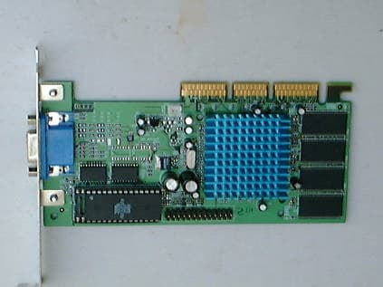
Click to zoom
Application Details
- Equipment Class
- JBP - Part 15 Class B Computing Device Peripheral
- Date of Grant
- Sep 25, 2001
- Application Purpose
- Original Equipment
- Date of Application
- Sep 25, 2001
- Equipment Note
- Video Card
- Company
- Althon Micro, Inc.
- Country
- United States
Documents & Files
Document Text
Text extracted from the exhibit documents filed with the FCC. Open a document above to read the original.
External Photos
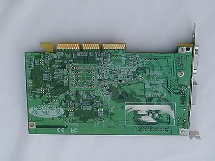
FCC ID: PQB-R128-P102 PHOTOGRAPH OF THE PRODUCT INNER CIRCUIT TOP VIEW INNER CIRCUIT BOTTOM VIEW
ID Label/Location Info
FCC ID: PQB-R128-P102 This device complies with part 15 of the FCC Rules. Operation is subject to the following two conditions: (1) this device may not cause harmful interference, and (2) this device must accept any interference received, including interference that may cause undesired operation.
ID Label/Location Info
FCC ID: PQB-R128-P102 LABEL LOCATION BOTTOM VIEW OF THE DEVICE WITH FCC ID LABEL FCC ID
Internal Photos
FCC ID: PQB-R128-P102 PHOTOGRAPH OF THE PRODUCT INNER CIRCUIT TOP VIEW INNER CIRCUIT BOTTOM VIEW
Test Report
Date: 2001-06-25 TEST REPORT Page1 of Page7 No.: HM105079 APPLICANT: (Code: ALM004) ALTHON MICRO INC. 280-290 S. Paseo Tesoro, Walnut, CA 91789, U.S.A. DATE OF SAMPLES RECEIVED: 2001-06-19 SUBMITTED SAMPLE(S): 1 sample DATE OF TESTING: 2001-06-22 DESCRIPTION OF SAMPLE(S): A sample of product said to be: Product:AGP VGA CARD Manufacturer:ALTHON MICRO INC. Model Number:R128-102 Brand Name:N/A Rating:The product was drawing power from the signal port of the console Origin:CHINA INVESTIGATIONS REQUESTED: Measurement to the relevant clauses of F.C.C. Rules and Regulations Part 15 Subpart C - Intentional Radiator. REMARK : This product was tested as a system using the Ancillary Equipment listed in Appendix B. RESULTS: Please see attached sheet(s). CONCLUSION: From the measurement data obtained, the tested sample was considered to have COMPLIED with the requirement for the relevant clauses of Federal Communications Commission Rules. TEST EQUIPMENT AUDIT: Please see Appendix A. Law Man KitSteven TsangPatrick Wong Test EngineerVerify byPatrick Wong for Managing Direct Date: 2001-06-25 TEST REPORT Page2 of Page7 No.: HM105079 T E S T S U M M A R Y (A)Measurement of Radiated Emission Result--Satisfactory Data--See the attached data (BMeasurement of Line-Conducted Voltage Test Result--Satisfactory Data--See the attached data Date: 2001-06-25 TEST REPORT Page3 of Page7 No.: HM105079 (A) Measurement of Radiated Interference TEST REFERENCE:FCC Rules Part 15 Subpart B Section 15.209 :(Class B) TEST CONDITION:Normal TEST DATE:2001-06-22 ================================================================== EmissionMeter ReadingPolarizationField StrengthFCC Limited Frequency(including antenna factor)(at 3m) MHzdB( μμ V)H-V μμ V/m μμ V/m 49.2228.2H25.70100 59.0223.4H14.79100 88.5011.6H3.80150 118.0424.2H16.22150 177.0936.4H66.07150 206.7738.5H84.14150 ================================================================== - End - ============= SUMMARY =============== All data is within limits ======================================== Broad-band Antennas were used and both polarizations of emissions were measured. polarizations at highest reading indicated as: H -- HorizontalV -- Vertical ======================================== Quasi-peak measurements were performed if the maximised measurements were less than 6dB below the quasi-peak limit line. Quasi-peak measurements are denoted by * in the table above Date: 2001-06-25 TEST REPORT Page4 of Page7 No.: HM105079 NOTES FOR THE RADIATION MEASUREMENT (1) Test site facility: Open field test site located at Taipo (Hong Kong) with a metal ground plane in compliance with the requirements of ANSI C63.4:1992. (2) Test Equipment: HP 8572A EMI receiver was set to CISPR quasi-peak mode and the bandwidth of the receiver was set to 100KHz or 1MHz depending on the type of signal. A biconical log- Periodic antenna was used for frequency range from 30MHz to 1000MHz. (3) Test Set-Up: The EUT and support equipment are placed in accordance with ANSI C63.4. (4) Measuring Procedure: An initial pre-scan measurement was performed in a semi-anechoic chamber using a 25dB gain pre-amplifier. The receive antenna in the chamber was 1.5m above the groundplane and 3m from the sample. The sample was placed 0.8m above the groundplane. Measurements in both horizontal and vertical polarities were performed. All emissions recorded during the prescan were subsequently remeasured on the open field test site (described in 1 above) using the following procedure:The ambient noise scanning was made before powering on the EUT and support equipment to identify the emissions from the environment. During the test, each emission was maximized by: having the EUT continuously working, arranging, rotating turntable and manipulating interconnecting cables, rotating turntable and varying antenna height from 1m to 4m in both horizontal and vertical polarizations. The frequency range tested is from 30MHz to 1000MHz and the worst-case emissions are shown in Test Results. (5) Measuring Uncertainty: The calculated uncertainty for measurement performed at 3M test distance are:- 30MHz to 300MHz = +3.7dB, 300MHz to 1000MHz = +3.0dB/-2.7dB. (6) Address of test site facility: The Hong Kong Standards & Testing Centre Ltd. 10 Dai Wang Street, Taipo Industrial Estate, Taipo, N.T., Hong Kong Date: 2001-06-25 TEST REPORT Page5 of Page7 No.: HM105079 (B) Measurement of Line-Conducted Voltage onto AC Power Line TEST REFERENCE:FCC Rules Part 15 Subpart B Section 15.209 TEST CONDITION:Normal TEST DATE:2001-06-22 (1) Between “Live” and “Ground” =================================================================== Frequency Range of EmissionMaximum Measured Radio NoiseFCC Limit (Class B) MHzdB( μμ V) μμ V μμ V 0.45-0.80<39.6295.72250.00 0.80-1.60<41.04112.72250.00 1.60-3.0037.0671.29250.00 3.00-5.00<20.1110.13250.00 5.00-7.0015.355.85250.00 7.00-9.00<14.235.15250.00 9.00-11.00<16.256.49250.00 11.00-13.00<12.564.25250.00 13.00-15.00<18.478.38250.00 15.00-17.0017.337.35250.00 17.00-19.000.001.00250.00 19.00-21.000.001.00250.00 21.00-23.0018.958.86250.00 23.00-25.000.001.00250.00 25.00-27.0012.964.45250.00 27.00-30.000.001.00250.00 ================================================================= - End - ================================================ ========== SUMMARY ========== All data is within limits ================================= Date: 2001-06-25 TEST REPORT Page6 of Page7 No.: HM105079 (B) Measurement of Line-Conducted Voltage onto AC Power Line TEST REFERENCE:FCC Rules Part 15 Subpart B Section 15.107(a) :(Class B) TEST CONDITION:Normal TEST DATE:2001-06-22 (1) Between "Neutral” and "Ground” =================================================================== Frequency Range of EmissionMaximum Measured Radio NoiseFCC Limit (Class B) MHzdB( μμ V) μμ V μμ V 0.45-0.8039.6295.72250.00 0.80-1.6041.04112.72250.00 1.60-3.00<37.0671.29250.00 3.00-5.0020.1110.13250.00 5.00-7.00<15.355.85250.00 7.00-9.0014.235.15250.00 9.00-11.0016.256.4925…
Text truncated - open the document above for the full version.
Test Report
FCC ID: PQB-R128-P102 Test Results Emission Radiated Emissions Test Requirement: FCC 47CFR 15.109 Class B Test Method:ANSI C63.4:1992 Test Date:2001-09-17 Mode of Operation:On mode Test Method: The sample was placed 0.8m above the ground plane on the OATS *. Measurements in both horizontal and vertical polarities were performed. During the test, each emission was maximized by: having the EUT continuously working, investigate all operating modes, rotated about all 3 axis (X, Y & Z) to obtain worst position, manipulating interconnecting cables, rotating turntable, varying antenna height from 1m to 4m in both horizontal and vertical polarizations. The emissions worst-case are shown in Test Results of the following pages. *:OATS [Open area test site] located at HKSTC with a metal ground plane on filed with the FCC pursuant to section 2.948 of the FCC rules, with Registration Number: 90657. Test Setup: EUT distance = 3m Pre -Amplifier Receiver Turn Table Computer Ground plane FCC ID: PQB-R128-P102 Limited for Radiated Emissions [FCC 47 CFR 15.109 Class B]: Frequency RangeQuasi-Peak Limits [MHz][μV/m] 30-88100 88-216150 216-960200 Above960500 The emission limits shown in the above table are based on measurement employing a CISPR quasi-peak detector and above 1000MHz are base on measurements employing an average detector. Results: Radiated Emissions Average Value FrequencyLevel @3m Correction Factor Field Strength Field Strength Limit @3m Antenna Polarity MHz dBμV dB/m dBμV/mμV/mμV/m NO EMISSION DETECTED WITHIN 20dB OF THE FCC LIMITS ** For effective averaging, the bandwidth of the video filter must be smaller than the resolution bandwidth. The higher the ratio of resolution bandwidth to video bandwidth, the greater the averaging will be recorded. .Below setting for HP8572A EMI Receiver. Resolution Bandwidth =3MHz Video Bandwidth =1Hz FCC ID: PQB-R128-P102 TEST EQUIPMENT AUDIT Pre-scan EQP NO.DESCRIPTIONMANUFACTURERMODEL NO.SERIAL NO.LAST CAL EM131PORTABLE SPECTRUM ANALYSERHEWLETT PACKARD8595EM3710A0015510/07/00 EM016ANTENNAARA INC.LPB-2513/A104708/11/00 EM034PRE-AMPLIFIERHP8447F OPT 16642944A0424018/07/00 EM082ANECHOIC CHAMBERFELJAS & MASSONN/AN/ATBD Radiated Emission EQP NO.DESCRIPTIONMANUFACTURERMODEL NO.SERIAL NO.LAST CAL EM007SPECTRUM ANALYZERHEWLETT PACKARDHP85660B3144A2119207/09/01 EM008SPECTRUM ANALYZER DISPLAYHEWLETT PACKARDHP85662A3144A2051407/09/01 EM009QUASI PEAK ADAPTORHEWLETT PACKARDHP85650A3303A0170207/09/01 EM010RF PRESELECTORHEWLETT PACKARDHP85685A3221A0141007/09/01 EM011ATTENNUATOR/SWITCHHEWLETT PACKARDHP11713A2508A1059507/09/01 EM012PRE-AMPLIFIERHEWLETT PACKARDHP8449B3008A0026207/09/01 EM013CONTROLLER (COMPUTER), COLOR MONITOR, KEYBOARD & MOUSE FLOPPY DRIVE HEWLETT PACKARD HEWLETT PACKARD HEWLETT PACKARD HP9000 HP A1097C HP9133L 6226A60314 3151J39517 2623A02468 CM EM131PORTABLE SPECTRUM ANALYSERHEWLETT PACKARD8595EM3710A0015510/07/00 EM017ANTENNAARA INC.LPB-2513/A106917/02/00 EM020HORN ANTENNAEMCO3115403209/08/00 EM072SIGNAL GENERATORHEWLETT PACKARD8640B1948A1189230/03/98 EM083HKSTC OPEN AREA TEST SITEHKSTCN/AN/A16/01/01 EM145EMI TEST RECEIVERR & SESCS 30830245/021TBD EM174ANTENNAEMCO3142B167118/06/01
Test Report
Marianne Bosley To:[email protected] Subject:Althon Micro FCC ID:PQB-R128-P102; Althon Micro FCC ID:PQB-R128- P106; Althon Micro FCc ID:PQB-RV100-P112 Hi Alice, Our engineer has reviewed the three Althon Micro applications and has found the same issue with each one. Please answer the question below, and submit the required additional data, for each one. When you have done this, and completed the administrative issue of the 15.105 statement wording in the manuals, the Grants can be issued. If you have any further questions, please let me know. Have a good day. Marianne RT Question: 1. The EUT contains an oscillator at 125 MHz. Pursuant to Section 15.33(b)(1), the radiated emissions from this device must be measured up to 2 GHz. It was only measure up to 1 GHz. Please measure radiated emissions up to 2 GHz and submit additional data, along with a description of the test procedure used, including detector function and RBW/VBW. Marianne T. Bosley EMC Admi nistrator 410-354-3300, ext. 412
Test Setup Photos
FCC ID: PQB-R128-P102 TEST SET UP PHOTOGRAPH OF THE PRODUCT MEASUREMENT OF RADIATED EMISSION TEST SET UP FCC ID: PQB-R128-P102 MEASUREMENT OF LINE-CONDUCTED VOLTAGE TEST SET UP
Contact Information
Applicant
K.D. Au(President)
Test Firm
Hong Kong Standards & Testing Cen.Wilson Wong
Technical Specifications
| # | Rule Parts | Frequency Range | Power Output |
|---|---|---|---|
| 1 | 15B | - | - |
Other Applications from Althon Micro, Inc.
PQB-RDN-P119
Nov 13, 2001Video Card
Equipment Class
JBP - Part 15 Class B Computing Device Peripheral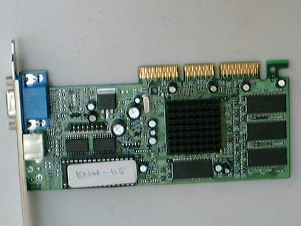
PQB-RV100-P112
Oct 08, 2001Video Card
Equipment Class
JBP - Part 15 Class B Computing Device Peripheral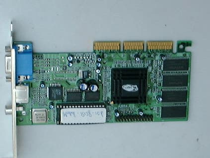
PQB-R128-P106
Sep 25, 2001Video Card
Equipment Class
JBP - Part 15 Class B Computing Device Peripheral