PQXHKG2003GMRS
H K Protech, Inc.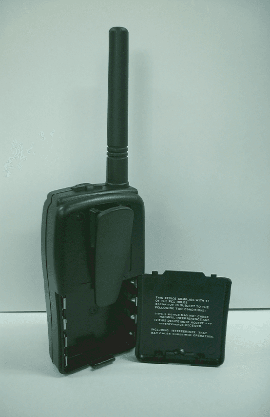
Click to zoom
Application Details
- Equipment Class
- TNF - Licensed Non-Broadcast Transmitter Held to Face
- Date of Grant
- Jan 30, 2002
- Application Purpose
- Original Equipment
- Date of Application
- Sep 03, 2001
- Equipment Note
- GMRS
- Frequency Range
- 462.56250000 - 462.72500000
- Company
- H K Protech, Inc.
- Country
- South Korea
Documents & Files
Document Text
Text extracted from the exhibit documents filed with the FCC. Open a document above to read the original.
Users Manual
GMRS 2003 1 2 3 4 5 14 1 A - 2 LIquid Crysta l Displa y LIquid Crysta l Displa y 1 2 OPERATION OPERATION OPERATION OPERATION OPERATION OPERATION OPERATION OPERATION 1. Press button until the Lock Icon flashes with "Of" display, pressing Up / Down button will change to Lock "On" position. 2. Press PWR(Enter) button to confirm Lock on position. (Lock Icon display on LCD) 3. Lock will be OFF by pressing button longer than 2 seconds. (Lock Icon disappear) Selection 1. Press button until VOX Icon flashes with "Of" or on level "1- 3" display, pressing Up / Down button will change to VOX Off or On- level 1- 3. 2. Press PWR(Enter) button to confirm VOX OFF or ON- level sensitvity 1 t o 3. (VOX Icon disappear or display on LCD) * VOX(Voice Activated Transm ission) on allows you that speaking without pressing the PTT Button activate the unit to transm it the conversation. * OPERATION OPERATION 1. Press button until Vibration Icon flashes with "On" or "Of" display, pressing Up / Down button will change to on or off. 2. Press PWR(Enter) button to confirm . (Vibration Icon display on LCD or disappear) 1. Press button unit Roger Icon flashes with "On" or "Of" display, pressing Up / Down button will change to on or off. 2. Press PWR(Enter) button to confirm . (Roger icon display on LCD or disappear) * Roger Tone on condition will send audible tone to your listener when you release PTT button to alert you finish talk* OPERATION OPERATION 1. Press button until the "H"or "L" icon flashes with "Po" display, pressing Up / Down button will change high or low power. 2. Press PWR(Enter) button to confirm . (LCD display either H or L icon) *High is norm al operation, but you can switch to Low Tx power to extend battery life when in close proxim ity to other party or clear weather condition. * * Rx channel scan searches for action signals in an endless loop from 1 to 15 or from 15 to 1. * (LCD display Scan icon) OPERATION OPERATION Press and hold PTT button to talk and release PTT button to listen for response(LCD display Tx Icon) Press PTT and (m onitor) button sam e tim e to send Call Alert to nearby receivers set to the sam e m ain channel. (LCD display Tx Icon) OPERATION OPERATION 1. Furnished Auto Squelch can be tem porarily rem oved by pressing Monitor button longer than 5 seconds which will allow receive all the signals for the selected m ain channel. (LCD display Rx Icon) 2. To return to norm al operation (Auto squelch), press button again. CTCSS Sub- Channels
Cover Letter(s)
Form Letters2 TIMCO TIMCOTIMCO TIMCO ENGINEERING INC. 849 NW State Road 45 Newberry, Florida 32669 http://www.timcoengr.com 888.472.2424 F 352.472.2030 email: tei@t imcoengr.com 14 November 2001 Mr. Stan Lyles Federal Communications Commission Authorization and Evaluation Division 7435 Oakland Mills Road Columbia, MD 21046 SUBJECT: HK PROTECH, INC FCC ID: PQXHKG2003 CONFIRMATION #: EA102245 CORRESPONDENCE ID: 21025 Dear Mr. Lyles: 1. Attached you will find a new test report in which the RF power output is 1.4Watts. The manufacturer decided because of the time required to obtain SAR on a 3Watt unit to change this application to a 1.4Watt unit. They feel that they should do this now and go after a 3Watt unit as soon as possible with a different model number. This will allow them to hopefully sell this unit soon. We’ve uploaded a revised test report. This letter will also serve as a request to change the output power on the 731 form as follows: HIGH POWER 1.4 WATTS LOW POWER .30 WATTS 2. The DC voltage is 6.0 volts. We have corrected page 2 of the test report and uploaded it to you. 3. The output power shown is ERP. 4. We have included the new data for battery end-point in the test report that we uploaded to you today. If you have any questions please let me know. Sincerely, Sid Sanders
Cover Letter(s)
Form Letters2 TIMCO TIMCOTIMCO TIMCO ENGINEERING INC. 849 NW State Road 45 Newberry, Florida 32669 http://www.timcoengr.com 888.472.2424 F 352.472.2030 email: tei@t imcoengr.com 14 November 2001 Mr. Stan Lyles Federal Communications Commission Authorization and Evaluation Division 7435 Oakland Mills Road Columbia, MD 21046 SUBJECT: HK PROTECH, INC FCC ID: PQXHKG2003 CONFIRMATION #: EA102245 CORRESPONDENCE ID: 21025 Dear Mr. Lyles: 1. Attached you will find a new test report in which the RF power output is 1.4Watts. The manufacturer decided because of the time required to obtain SAR on a 3Watt unit to change this application to a 1.4Watt unit. They feel that they should do this now and go after a 3Watt unit as soon as possible with a different model number. This will allow them to hopefully sell this unit soon. We’ve uploaded a revised test report. This letter will also serve as a request to change the output power on the 731 form as follows: HIGH POWER 1.4 WATTS LOW POWER .30 WATTS 2. The DC voltage is 6.0 volts. We have corrected page 2 of the test report and uploaded it to you. 3. The output power shown is ERP. 4. We have included the new data for battery end-point in the test report that we uploaded to you today. If you have any questions please let me know. Sincerely, Sid Sanders
Cover Letter(s)
Form Letters2 TIMCO TIMCOTIMCO TIMCO ENGINEERING INC. 849 NW State Road 45 Newberry, Florida 32669 http://www.timcoengr.com 888.472.2424 F 352.472.2030 email: tei@t imcoengr.com 14 November 2001 Mr. Stan Lyles Federal Communications Commission Authorization and Evaluation Division 7435 Oakland Mills Road Columbia, MD 21046 SUBJECT: HK PROTECH, INC FCC ID: PQXHKG2003 CONFIRMATION #: EA102245 CORRESPONDENCE ID: 21025 Dear Mr. Lyles: 1. Attached you will find a new test report in which the RF power output is 1.4Watts. The manufacturer decided because of the time required to obtain SAR on a 3Watt unit to change this application to a 1.4Watt unit. They feel that they should do this now and go after a 3Watt unit as soon as possible with a different model number. This will allow them to hopefully sell this unit soon. We’ve uploaded a revised test report. This letter will also serve as a request to change the output power on the 731 form as follows: HIGH POWER 1.4 WATTS LOW POWER .30 WATTS 2. The DC voltage is 6.0 volts. We have corrected page 2 of the test report and uploaded it to you. 3. The output power shown is ERP. 4. We have included the new data for battery end-point in the test report that we uploaded to you today. If you have any questions please let me know. Sincerely, Sid Sanders
Cover Letter(s)
TIMCO TIMCOTIMCO TIMCO ENGINEERING INC. 849 NW State Road 45 Newberry, Florida 32669 http://www.timcoengr.com December 13, 2001 Mr. Stan Lyles Federal Communications Commission Authorization and Evaluation Division 7435 Oakland Mills Road Columbia, MD 21046 SUBJECT: HK PROTECH, INC FCC ID: PQXHKG2003 CONFIRMATION #: EA102245 CORRESPONDENCE ID: 21271 Dear Mr. Lyles: 1. Please indicate how you change the output power and what changes to the device are made. The output was reduced by applying the following modifications: R314 was changed from 2.2K to 4.7K 2. Please update tune up info. I have uploaded the revised tuning procedure with this letter . 3. Please update users manual. I have uploaded the revised users manual with this letter. 4. Please note that the attenuation requirement for spurious emissions is 43 + 10Log(P) dB. This is referenced to the desired signal yielding dBc. The attenuation specification is not XX uV/M, or derived from absolute value of the field strength. The dBc is determined from the substitution method such as described in the ANSI/TIA/EIA-603-1992 document On the next page, please find the test data shown using the substitution method . 5. Page 9 of original test report shows frequency 925.0 MHz and coax loss is 1.95 dB. Please explain why is coax loss different in the test report you uploaded on 11/14/01. Frequency at 925.0 MHz and coax loss is 4.50 dB. Due to a software error here at Timco Engineering the coax loss that was reported in the original test report was incorrect. The correct coax loss should have been 4.5 dB. Since the next page was performed using the substitution method the field strength information is moot. Best regards, Mario de Aranzeta TIMCO TIMCOTIMCO TIMCO ENGINEERING INC. 849 NW State Road 45 Newberry, Florida 32669 http://www.timcoengr.com 2.1053 UNWANTED RADIATION: 95.635(b)(7) The tabulated Data shows the results of the radiated field strength emissions test. The spectrum was scanned from 30 to at least the 10th harmonic of the fundamental. This test was conducted per ANSI C63.4-1992. REQUIREMENTS: HIGH POWER: 43 + 10log(1.40) = 44.46 dB LOW POWER: 43 + 10log(0.30) = 37.77 dB TEST DATA: Substitution Method HIGH POWER Emission Frequency MHz dBc Margin dB 462.70 0.00 0.00 925.00 53.7 9.24 1388.00 71.51 27.05 1851.00 71.00 26.54 2314.00 73.85 29.39 2776.00 71.20 26.74 3239.00 56.85 12.39 3701.00 56.00 11.54 4164.00 60.14 15.68 4627.00 68.47 24.01 LOW POWER Emission Frequency MHz dBc Margin dB 462.70 0.00 0.0 925.00 58.14 20.37 1388.00 54.84 17.07 1851.00 70.33 32.56 2314.00 62.08 24.31 2776.00 69.93 32.16 3239.00 61.18 23.41 3701.00 60.73 22.96 4164.00 59.27 21.50 4627.00 70.40 32.63 METHOD OF MEASUREMENT: The tabulated data shows the results of the radiated field strength emissions test. The spectrum was scanned from 30 to at least the tenth harmonic of the fundamental. This test was conducted per TIA/EIA STANDARD 603 using the substitution method. Measurements were made at the open field test site of TIMCO ENGINEERING, INC. located at 849 NW State Road 45, Newberry, FL 32669.
Operational Description
4. CIRCUIT DESCRIPTION – – 5. Troubleshooting ProblemSolution No PowerRecharge or Replace Battery Message Not receivedMake sure the PTT button is completely pressed as you transmit. Reposition or replace batteries Message Not receivedConfirm transceivers have the same channel and privacy codes settings. Increase Volume level Release PTT Button Reception of unwanted signals Turn on the Codes mode and set code number to match the setting of the target transceiver. Cannot change channel and codes settings Make radio is unlocked. See page for more information. Low batteriesReplace batteries. GMRS License
Parts List/Tune Up Info
G M R S [HKP-2003] INSTRUCTION MANUAL 2-WAY HANDHELD RADIO - - - - - - - - - - - - - - ’ - - – - - - - - - - – –
Test Report
APPLICANT: HK PROTECH, INC. FCC ID: PQXHKG2003 DATE: AUGUST 29, 2001 REPORT #: H\HK\691YBK1\691YBK1RPT.doc PAGE #: TABLE OF CONTENTS TABLE OF CONTENTS LIST APPLICANT: HK PROTECH, INC FCC ID: PQXHKG2003 TEST REPORT: PAGE 1......COVER SHEET - GENERAL INFORMATION & TECHNICAL DESCR. PAGE 2......TECHNICAL DESCRIPTION CONTINUED & RF POWER OUTPUT PAGE 3-4....MODULATION CHARACTERISTICS PAGE 5......POST LIMITER FILTER PAGE 6-7....OCCUPIED BANDWIDTH PAGE 8......SPURIOUS EMISSIONS AT ANTENNA TERMINALS PAGE 9......UNWANTED RADIATION PAGE 10.....METHOD OF MEASURING SPURIOUS EMISSIONS PAGE 11.....FREQUENCY STABILITY PAGE 12.....LIST OF TEST EQUIPMENT EXHIBITS CONTAINING: EXHIBIT 1.........FCC ID LABEL SAMPLE EXHIBIT 2.........SKETCH OF LOCATION EXHIBIT 3.........EXTERNAL FRONT VIEW PHOTOGRAPH EXHIBIT 4.........EXTERNAL BACK VIEW PHOTOGRAPH EXHIBIT 5A-5B.....INTERNAL COMPONENT VIEW PHOTOGRAPH EXHIBIT 6A-6B.....INTERNAL COPPER VIEW PHOTOGRAPH EXHIBIT 7.........BLOCK DIAGRAM EXHIBIT 8.........SCHEMATIC EXHIBIT 9A-9P.....USER'S MANUAL EXHIBIT 10A-10B...CIRCUIT DESCRIPTION EXHIBIT 11A-11C...TUNING PROCEDURE EXHIBIT 12........TEST SET UP PHOTO APPLICANT: HK PROTECH, INC. FCC ID: PQXHKG2003 DATE: AUGUST 29, 2001 REPORT #: H\HK\691YBK1\691YBK1RPT.doc PAGE #: 1 OF 12 GENERAL INFORMATION REQUIRED FOR CERTIFICATION 2.1033(c)(1)(2) HK PROTECH, INC will manufacture the FCCID: PQXHKG2003 GMRS CHANNELS TRANSCEIVER in quantity, for use under FCC RULES PART 95. HK PROTECH, INC 3-10, CHUNGCHUN-DONG, BUPYUNG-GU INCHON KOREA 2.1033 (c) TECHNICAL DESCRIPTION 2.1033(c)(3) Instruction book. A draft copy of the instruction manual is included as EXHIBIT 9A-9P. 2.1033(c) (4) Type of Emission: 9K5F3E 95.631 Bn = 2M + 2DK M = 3000 D = 1.75K Bn = 2(3.0)+2(1.75) = 9.5K Authorized Bandwidth 20.0KHz 2.1033(c)(5) Frequency Range: 462.5625 - 462.7250 MHz 95.621 2.10311c)(6)(7) The Maximum Output Power Rating: High: 3.245 Watts ERP Low: .5 Watt ERP 2.1033(c)(8) DC Voltages and Current into Final Amplifier: FINAL AMPLIFIER ONLY FOR LOW POWER SETTING INPUT POWER: (6.0V)(.210A) = 1.26 Watts FOR HIGH POWER SETTING INPUT POWER: (6.0V)(.600A) =3.60 Watts 2.1033(c)(9) Tune-up procedure. The tune-up procedure is included 11A-11C. APPLICANT: HK PROTECH, INC. FCC ID: PQXHKG2003 DATE: AUGUST 29, 2001 REPORT #: H\HK\691YBK1\691YBK1RPT.doc PAGE #: 2 OF 12 2.1033(c)(10) Complete Circuit Diagrams: The circuit diagram is included as EXHIBIT 8 of this report. The block diagrams are included as EXHIBIT 7 of this report. 2.1033(c)(11) A photograph or a drawing of the equipment identification label is included as exhibit No. 1. 2.1033(c)(12) Photographs(8"X10") of the equipment of sufficient clarity to reveal equipment construction and layout, including meters, labels for controls, including any view under shields. See exhibits 3-6B. 2.1033(c)(13) Digital modulation is not allowed. 2.1033(c)(14) The data required by 2.1046 through 2.1057 is submitted below. 95.639 Power Output shall not exceed 50.0 Watts effective radiated power. There can be no provisions for 95.649 increasing the power or varying the power. RF power output. 2.1046(a) RF power is measured by connecting a 50 ohm, resistive watt meter to the RF output connector. With a nominal battery voltage of 8.4 V, and the transmitter properly adjusted the RF output measures: OUTPUT POWER: HIGH: 3.245 Watts LOW: 0.50 Watt 2.1046(a) RF power output. The test procedure used was TIA/EIA-603 S2.2.1. APPLICANT: HK PROTECH, INC. FCC ID: PQXHKG2003 DATE: AUGUST 29, 2001 REPORT #: H\HK\691YBK1\691YBK1RPT.doc PAGE #: 3 OF 12 2.1047(a)(b) Modulation characteristics: AUDIO FREQUENCY RESPONSE The audio frequency response was measured in ac- cordance with TIA/EIA Specification 603. The audio frequency response curve is shown on the next page. The audio signal was fed into a dummy microphone circuit and into the microphone connector. The input required to produce 30 percent modulation level was measured. HK Protech HKG 2003 0 5 10 15 20 25 30 100100010000 Frequency rms mVolts audio response 2.1047(b) Audio input versus modulation The audio input level needed for a particular per- percentage of modulation was measured in accor- dance with TIA/EIA Specification 603. The audio input curves versus modulation are on the following pages. Curves are provided for audio input frequen- cies of 300, 1000, and 3000 Hz. Modulation Limiting HK Protech Inc HKG2003 0 200 400 600 800 1000 1200 1400 050100150200250 rms mVolts Deviation 300 Hz APPLICANT: HK PROTECH, INC. FCC ID: PQXHKG2003 DATE: AUGUST 29, 2001 REPORT #: H\HK\691YBK1\691YBK1RPT.doc PAGE #: 4 OF 12 Modulation Limiting HK Protech Inc HKG2003 0 500 1000 1500 2000 051015 rms mVolts Deviation 1000 Hz Modulation Limiting HK Protech Inc HKG2003 0 500 1000 1500 2000 020406080 rms mVolts Deviation 3000 Hz APPLICANT: HK PROTECH, INC. FCC ID: PQXHKG2003 DATE: AUGUST 29, 2001 REPORT #: H\HK\691YBK1\691YBK1RPT.doc PAGE #: 5 OF 12 95.637 Post Limiter Filter Each GMRS transmitter, except a mobile station transmitter with a power of 2.5Watts or less, must be equipped with an audio low pass filter. At any frequency between 3 & 20KHz the filter must have an attenuation of 60log (f/3) greater than the attenuation at 1KHz. APPLICANT: HK PROTECH, INC. FCC ID: PQXHKG2003 DATE: AUGUST 29, 2001 REPORT #: H\HK\691YBK1\691YBK1RPT.doc PAGE #: 6 OF 12 2.1049 Occupied bandwidth: 95.635(b)(1)(3)(7) At least 25dB on any frequency removed from the center of the authorized bandwidth by more than 50%up to and including 100% of the authorized bandwidth. At least 35 dB on any frequency removed from the center of the authorized BW by more than 100% up to and including 250% of the authorized BW. At least 43+log10(T) on any frequency removed from the center of the authorized bandwidth by more than 250%. Occupied Bandwidth Plot Occupied Bandwidth Plot APPLICANT: HK PROTECH, INC. FCC ID: PQXHKG2003 DATE: AUGUST 29, 2001 REPORT #: H\HK\691YBK1\691YBK1RPT.doc PAGE #: 7 OF 12 APPLICANT: HK PROTECH, INC. FCC ID:…
Text truncated - open the document above for the full version.
Test Report
APPLICANT: HK PROTECH, INC. FCC ID: PQXHKG2003 DATE: AUGUST 29, 2001 REPORT #: H\HK\691YBK1\691YBK1RPT.doc PAGE #: TABLE OF CONTENTS TABLE OF CONTENTS LIST APPLICANT: HK PROTECH, INC FCC ID: PQXHKG2003 TEST REPORT: PAGE 1......COVER SHEET - GENERAL INFORMATION & TECHNICAL DESCR. PAGE 2......TECHNICAL DESCRIPTION CONTINUED & RF POWER OUTPUT PAGE 3-4....MODULATION CHARACTERISTICS PAGE 5......POST LIMITER FILTER PAGE 6-7....OCCUPIED BANDWIDTH PAGE 8......SPURIOUS EMISSIONS AT ANTENNA TERMINALS PAGE 9......UNWANTED RADIATION PAGE 10.....METHOD OF MEASURING SPURIOUS EMISSIONS PAGE 11.....FREQUENCY STABILITY PAGE 12.....LIST OF TEST EQUIPMENT EXHIBITS CONTAINING: EXHIBIT 1.........FCC ID LABEL SAMPLE EXHIBIT 2.........SKETCH OF LOCATION EXHIBIT 3.........EXTERNAL FRONT VIEW PHOTOGRAPH EXHIBIT 4.........EXTERNAL BACK VIEW PHOTOGRAPH EXHIBIT 5A-5B.....INTERNAL COMPONENT VIEW PHOTOGRAPH EXHIBIT 6A-6B.....INTERNAL COPPER VIEW PHOTOGRAPH EXHIBIT 7.........BLOCK DIAGRAM EXHIBIT 8.........SCHEMATIC EXHIBIT 9A-9P.....USER'S MANUAL EXHIBIT 10A-10B...CIRCUIT DESCRIPTION EXHIBIT 11A-11C...TUNING PROCEDURE EXHIBIT 12........TEST SET UP PHOTO APPLICANT: HK PROTECH, INC. FCC ID: PQXHKG2003 DATE: AUGUST 29, 2001 REPORT #: H\HK\691YBK1\691YBK1RPT.doc PAGE #: 1 OF 12 GENERAL INFORMATION REQUIRED FOR CERTIFICATION 2.1033(c)(1)(2) HK PROTECH, INC will manufacture the FCCID: PQXHKG2003 GMRS CHANNELS TRANSCEIVER in quantity, for use under FCC RULES PART 95. HK PROTECH, INC 3-10, CHUNGCHUN-DONG, BUPYUNG-GU INCHON KOREA 2.1033 (c) TECHNICAL DESCRIPTION 2.1033(c)(3) Instruction book. A draft copy of the instruction manual is included as EXHIBIT 9A-9P. 2.1033(c) (4) Type of Emission: 9K5F3E 95.631 Bn = 2M + 2DK M = 3000 D = 1.75K Bn = 2(3.0)+2(1.75) = 9.5K Authorized Bandwidth 20.0KHz 2.1033(c)(5) Frequency Range: 462.5625 - 462.7250 MHz 95.621 2.10311c)(6)(7) The Maximum Output Power Rating: High: 1.40 Watts ERP Low: .30 Watt ERP 2.1033(c)(8) DC Voltages and Current into Final Amplifier: FINAL AMPLIFIER ONLY FOR LOW POWER SETTING INPUT POWER: (6.0V)(.210A) = 1.26 Watts FOR HIGH POWER SETTING INPUT POWER: (6.0V)(.600A) =3.60 Watts 2.1033(c)(9) Tune-up procedure. The tune-up procedure is included 11A-11C. APPLICANT: HK PROTECH, INC. FCC ID: PQXHKG2003 DATE: AUGUST 29, 2001 REPORT #: H\HK\691YBK1\691YBK1RPT.doc PAGE #: 2 OF 12 2.1033(c)(10) Complete Circuit Diagrams: The circuit diagram is included as EXHIBIT 8 of this report. The block diagrams are included as EXHIBIT 7 of this report. 2.1033(c)(11) A photograph or a drawing of the equipment identification label is included as exhibit No. 1. 2.1033(c)(12) Photographs(8"X10") of the equipment of sufficient clarity to reveal equipment construction and layout, including meters, labels for controls, including any view under shields. See exhibits 3-6B. 2.1033(c)(13) Digital modulation is not allowed. 2.1033(c)(14) The data required by 2.1046 through 2.1057 is submitted below. 95.639 Power Output shall not exceed 50.0 Watts effective radiated power. There can be no provisions for 95.649 increasing the power or varying the power. RF power output. 2.1046(a) RF power is measured by connecting a 50 ohm, resistive watt meter to the RF output connector. With a nominal battery voltage of 6.0 V, and the transmitter properly adjusted the RF output measures: OUTPUT POWER: HIGH: 1.40 Watts ERP LOW: 0.30 Watt ERP 2.1046(a) RF power output. The test procedure used was TIA/EIA-603 S2.2.1. APPLICANT: HK PROTECH, INC. FCC ID: PQXHKG2003 DATE: AUGUST 29, 2001 REPORT #: H\HK\691YBK1\691YBK1RPT.doc PAGE #: 3 OF 12 2.1047(a)(b) Modulation characteristics: AUDIO FREQUENCY RESPONSE The audio frequency response was measured in ac- cordance with TIA/EIA Specification 603. The audio frequency response curve is shown on the next page. The audio signal was fed into a dummy microphone circuit and into the microphone connector. The input required to produce 30 percent modulation level was measured. HK Protech HKG 2003 0 5 10 15 20 25 30 100100010000 Frequency rms mVolts audio response 2.1047(b) Audio input versus modulation The audio input level needed for a particular per- percentage of modulation was measured in accor- dance with TIA/EIA Specification 603. The audio input curves versus modulation are on the following pages. Curves are provided for audio input frequen- cies of 300, 1000, and 3000 Hz. Modulation Limiting HK Protech Inc HKG2003 0 200 400 600 800 1000 1200 1400 050100150200250 rms mVolts Deviation 300 Hz APPLICANT: HK PROTECH, INC. FCC ID: PQXHKG2003 DATE: AUGUST 29, 2001 REPORT #: H\HK\691YBK1\691YBK1RPT.doc PAGE #: 4 OF 12 Modulation Limiting HK Protech Inc HKG2003 0 500 1000 1500 2000 051015 rms mVolts Deviation 1000 Hz Modulation Limiting HK Protech Inc HKG2003 0 500 1000 1500 2000 020406080 rms mVolts Deviation 3000 Hz APPLICANT: HK PROTECH, INC. FCC ID: PQXHKG2003 DATE: AUGUST 29, 2001 REPORT #: H\HK\691YBK1\691YBK1RPT.doc PAGE #: 5 OF 12 95.637 Post Limiter Filter Each GMRS transmitter, except a mobile station transmitter with a power of 2.5Watts or less, must be equipped with an audio low pass filter. At any frequency between 3 & 20KHz the filter must have an attenuation of 60log (f/3) greater than the attenuation at 1KHz. APPLICANT: HK PROTECH, INC. FCC ID: PQXHKG2003 DATE: AUGUST 29, 2001 REPORT #: H\HK\691YBK1\691YBK1RPT.doc PAGE #: 6 OF 12 2.1049 Occupied bandwidth: 95.635(b)(1)(3)(7) At least 25dB on any frequency removed from the center of the authorized bandwidth by more than 50%up to and including 100% of the authorized bandwidth. At least 35 dB on any frequency removed from the center of the authorized BW by more than 100% up to and including 250% of the authorized BW. At least 43+log10(T) on any frequency removed from the center of the authorized bandwidth by more than 250%. Occupied Bandwidth Plot Occupied Bandwidth Plot APPLICANT: HK PROTECH, INC. FCC ID: PQXHKG2003 DATE: AUGUST 29, 2001 REPORT #: H\HK\691YBK1\691YBK1RPT.doc PAGE #: 7 OF 12 APPLICANT: HK PROTECH, INC. …
Text truncated - open the document above for the full version.
Test Report
APPLICANT: HK PROTECH, INC. FCC ID: PQXHKG2003 DATE: AUGUST 29, 2001 REPORT #: H\HK\691YBK1\691YBK1RPT.doc PAGE #: TABLE OF CONTENTS TABLE OF CONTENTS LIST APPLICANT: HK PROTECH, INC FCC ID: PQXHKG2003 TEST REPORT: PAGE 1......COVER SHEET - GENERAL INFORMATION & TECHNICAL DESCR. PAGE 2......TECHNICAL DESCRIPTION CONTINUED & RF POWER OUTPUT PAGE 3-4....MODULATION CHARACTERISTICS PAGE 5......POST LIMITER FILTER PAGE 6-7....OCCUPIED BANDWIDTH PAGE 8......SPURIOUS EMISSIONS AT ANTENNA TERMINALS PAGE 9......UNWANTED RADIATION PAGE 10.....METHOD OF MEASURING SPURIOUS EMISSIONS PAGE 11.....FREQUENCY STABILITY PAGE 12.....LIST OF TEST EQUIPMENT EXHIBITS CONTAINING: EXHIBIT 1.........FCC ID LABEL SAMPLE EXHIBIT 2.........SKETCH OF LOCATION EXHIBIT 3.........EXTERNAL FRONT VIEW PHOTOGRAPH EXHIBIT 4.........EXTERNAL BACK VIEW PHOTOGRAPH EXHIBIT 5A-5B.....INTERNAL COMPONENT VIEW PHOTOGRAPH EXHIBIT 6A-6B.....INTERNAL COPPER VIEW PHOTOGRAPH EXHIBIT 7.........BLOCK DIAGRAM EXHIBIT 8.........SCHEMATIC EXHIBIT 9A-9P.....USER'S MANUAL EXHIBIT 10A-10B...CIRCUIT DESCRIPTION EXHIBIT 11A-11C...TUNING PROCEDURE EXHIBIT 12........TEST SET UP PHOTO APPLICANT: HK PROTECH, INC. FCC ID: PQXHKG2003 DATE: AUGUST 29, 2001 REPORT #: H\HK\691YBK1\691YBK1RPT.doc PAGE #: 1 OF 12 GENERAL INFORMATION REQUIRED FOR CERTIFICATION 2.1033(c)(1)(2) HK PROTECH, INC will manufacture the FCCID: PQXHKG2003 GMRS CHANNELS TRANSCEIVER in quantity, for use under FCC RULES PART 95. HK PROTECH, INC 3-10, CHUNGCHUN-DONG, BUPYUNG-GU INCHON KOREA 2.1033 (c) TECHNICAL DESCRIPTION 2.1033(c)(3) Instruction book. A draft copy of the instruction manual is included as EXHIBIT 9A-9P. 2.1033(c) (4) Type of Emission: 9K5F3E 95.631 Bn = 2M + 2DK M = 3000 D = 1.75K Bn = 2(3.0)+2(1.75) = 9.5K Authorized Bandwidth 20.0KHz 2.1033(c)(5) Frequency Range: 462.5625 - 462.7250 MHz 95.621 2.10311c)(6)(7) The Maximum Output Power Rating: High: 1.40 Watts ERP Low: .30 Watt ERP 2.1033(c)(8) DC Voltages and Current into Final Amplifier: FINAL AMPLIFIER ONLY FOR LOW POWER SETTING INPUT POWER: (6.0V)(.210A) = 1.26 Watts FOR HIGH POWER SETTING INPUT POWER: (6.0V)(.600A) =3.60 Watts 2.1033(c)(9) Tune-up procedure. The tune-up procedure is included 11A-11C. APPLICANT: HK PROTECH, INC. FCC ID: PQXHKG2003 DATE: AUGUST 29, 2001 REPORT #: H\HK\691YBK1\691YBK1RPT.doc PAGE #: 2 OF 12 2.1033(c)(10) Complete Circuit Diagrams: The circuit diagram is included as EXHIBIT 8 of this report. The block diagrams are included as EXHIBIT 7 of this report. 2.1033(c)(11) A photograph or a drawing of the equipment identification label is included as exhibit No. 1. 2.1033(c)(12) Photographs(8"X10") of the equipment of sufficient clarity to reveal equipment construction and layout, including meters, labels for controls, including any view under shields. See exhibits 3-6B. 2.1033(c)(13) Digital modulation is not allowed. 2.1033(c)(14) The data required by 2.1046 through 2.1057 is submitted below. 95.639 Power Output shall not exceed 50.0 Watts effective radiated power. There can be no provisions for 95.649 increasing the power or varying the power. RF power output. 2.1046(a) RF power is measured by connecting a 50 ohm, resistive watt meter to the RF output connector. With a nominal battery voltage of 6.0 V, and the transmitter properly adjusted the RF output measures: OUTPUT POWER: HIGH: 1.40 Watts ERP LOW: 0.30 Watt ERP 2.1046(a) RF power output. The test procedure used was TIA/EIA-603 S2.2.1. APPLICANT: HK PROTECH, INC. FCC ID: PQXHKG2003 DATE: AUGUST 29, 2001 REPORT #: H\HK\691YBK1\691YBK1RPT.doc PAGE #: 3 OF 12 2.1047(a)(b) Modulation characteristics: AUDIO FREQUENCY RESPONSE The audio frequency response was measured in ac- cordance with TIA/EIA Specification 603. The audio frequency response curve is shown on the next page. The audio signal was fed into a dummy microphone circuit and into the microphone connector. The input required to produce 30 percent modulation level was measured. HK Protech HKG 2003 0 5 10 15 20 25 30 100100010000 Frequency rms mVolts audio response 2.1047(b) Audio input versus modulation The audio input level needed for a particular per- percentage of modulation was measured in accor- dance with TIA/EIA Specification 603. The audio input curves versus modulation are on the following pages. Curves are provided for audio input frequen- cies of 300, 1000, and 3000 Hz. Modulation Limiting HK Protech Inc HKG2003 0 200 400 600 800 1000 1200 1400 050100150200250 rms mVolts Deviation 300 Hz APPLICANT: HK PROTECH, INC. FCC ID: PQXHKG2003 DATE: AUGUST 29, 2001 REPORT #: H\HK\691YBK1\691YBK1RPT.doc PAGE #: 4 OF 12 Modulation Limiting HK Protech Inc HKG2003 0 500 1000 1500 2000 051015 rms mVolts Deviation 1000 Hz Modulation Limiting HK Protech Inc HKG2003 0 500 1000 1500 2000 020406080 rms mVolts Deviation 3000 Hz APPLICANT: HK PROTECH, INC. FCC ID: PQXHKG2003 DATE: AUGUST 29, 2001 REPORT #: H\HK\691YBK1\691YBK1RPT.doc PAGE #: 5 OF 12 95.637 Post Limiter Filter Each GMRS transmitter, except a mobile station transmitter with a power of 2.5Watts or less, must be equipped with an audio low pass filter. At any frequency between 3 & 20KHz the filter must have an attenuation of 60log (f/3) greater than the attenuation at 1KHz. APPLICANT: HK PROTECH, INC. FCC ID: PQXHKG2003 DATE: AUGUST 29, 2001 REPORT #: H\HK\691YBK1\691YBK1RPT.doc PAGE #: 6 OF 12 2.1049 Occupied bandwidth: 95.635(b)(1)(3)(7) At least 25dB on any frequency removed from the center of the authorized bandwidth by more than 50%up to and including 100% of the authorized bandwidth. At least 35 dB on any frequency removed from the center of the authorized BW by more than 100% up to and including 250% of the authorized BW. At least 43+log10(T) on any frequency removed from the center of the authorized bandwidth by more than 250%. Occupied Bandwidth Plot Occupied Bandwidth Plot APPLICANT: HK PROTECH, INC. FCC ID: PQXHKG2003 DATE: AUGUST 29, 2001 REPORT #: H\HK\691YBK1\691YBK1RPT.doc PAGE #: 7 OF 12 APPLICANT: HK PROTECH, INC. …
Text truncated - open the document above for the full version.
Test Report
APPLICANT: HK PROTECH, INC. FCC ID: PQXHKG2003 DATE: AUGUST 29, 2001 REPORT #: H\HK\691YBK1\691YBK1RPT.doc PAGE #: TABLE OF CONTENTS TABLE OF CONTENTS LIST APPLICANT: HK PROTECH, INC FCC ID: PQXHKG2003 TEST REPORT: PAGE 1......COVER SHEET - GENERAL INFORMATION & TECHNICAL DESCR. PAGE 2......TECHNICAL DESCRIPTION CONTINUED & RF POWER OUTPUT PAGE 3-4....MODULATION CHARACTERISTICS PAGE 5......POST LIMITER FILTER PAGE 6-7....OCCUPIED BANDWIDTH PAGE 8......SPURIOUS EMISSIONS AT ANTENNA TERMINALS PAGE 9......UNWANTED RADIATION PAGE 10.....METHOD OF MEASURING SPURIOUS EMISSIONS PAGE 11.....FREQUENCY STABILITY PAGE 12.....LIST OF TEST EQUIPMENT EXHIBITS CONTAINING: EXHIBIT 1.........FCC ID LABEL SAMPLE EXHIBIT 2.........SKETCH OF LOCATION EXHIBIT 3.........EXTERNAL FRONT VIEW PHOTOGRAPH EXHIBIT 4.........EXTERNAL BACK VIEW PHOTOGRAPH EXHIBIT 5A-5B.....INTERNAL COMPONENT VIEW PHOTOGRAPH EXHIBIT 6A-6B.....INTERNAL COPPER VIEW PHOTOGRAPH EXHIBIT 7.........BLOCK DIAGRAM EXHIBIT 8.........SCHEMATIC EXHIBIT 9A-9P.....USER'S MANUAL EXHIBIT 10A-10B...CIRCUIT DESCRIPTION EXHIBIT 11A-11C...TUNING PROCEDURE EXHIBIT 12........TEST SET UP PHOTO APPLICANT: HK PROTECH, INC. FCC ID: PQXHKG2003 DATE: AUGUST 29, 2001 REPORT #: H\HK\691YBK1\691YBK1RPT.doc PAGE #: 1 OF 12 GENERAL INFORMATION REQUIRED FOR CERTIFICATION 2.1033(c)(1)(2) HK PROTECH, INC will manufacture the FCCID: PQXHKG2003 GMRS CHANNELS TRANSCEIVER in quantity, for use under FCC RULES PART 95. HK PROTECH, INC 3-10, CHUNGCHUN-DONG, BUPYUNG-GU INCHON KOREA 2.1033 (c) TECHNICAL DESCRIPTION 2.1033(c)(3) Instruction book. A draft copy of the instruction manual is included as EXHIBIT 9A-9P. 2.1033(c) (4) Type of Emission: 9K5F3E 95.631 Bn = 2M + 2DK M = 3000 D = 1.75K Bn = 2(3.0)+2(1.75) = 9.5K Authorized Bandwidth 20.0KHz 2.1033(c)(5) Fre…
Text truncated - open the document above for the full version.
Contact Information
Applicant
Young C Choy(Vice President)
Technical Contact
Timco Engineering, Inc.Mario R de Aranzeta
[email protected]352-472-5500
849 NW State Road 45 · Newberry, Florida · United States
Non-Technical Contact
Timco Engineering, Inc.Sharon A Hoffman
[email protected]352-472-5500
Test Firm
Timco Engineering, Inc.S Sanders
Technical Specifications
| # | Rule Parts | Frequency Range | Power Output | Emission | Tolerance |
|---|---|---|---|---|---|
| 2 | 95A | 462.5625 MHz - 462.725 MHz | 300.00 mW | 9K50F3E | 0.0005 % |
Other Applications from H K Protech, Inc.

PQXHKM1002
Jul 24, 2002MURS Transceiver
Equipment Class
TNF - Licensed Non-Broadcast Transmitter Held to Face