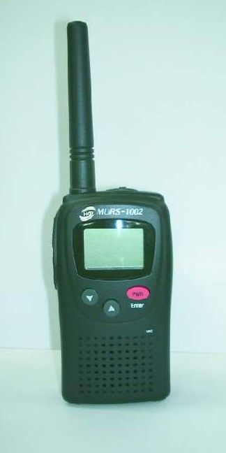
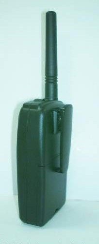
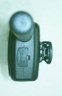
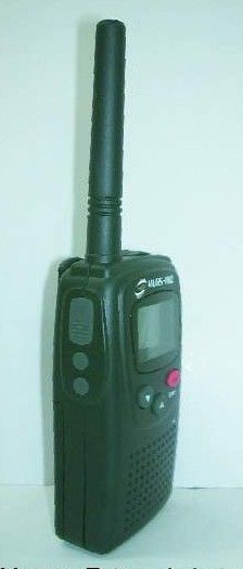
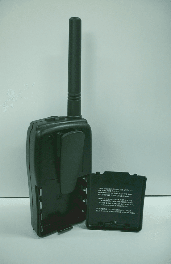
PQXHKM1002MURS Transceiver
H K Protech, Inc.
Click to zoom
Application Details
- Equipment Class
- TNF - Licensed Non-Broadcast Transmitter Held to Face
- Date of Grant
- Jul 24, 2002
- Application Purpose
- Original Equipment
- Date of Application
- Jun 18, 2002
- Equipment Note
- MURS Transceiver
- Frequency Range
- 151.82000000 - 154.60000000
- Company
- H K Protech, Inc.
- Country
- South Korea
Documents & Files
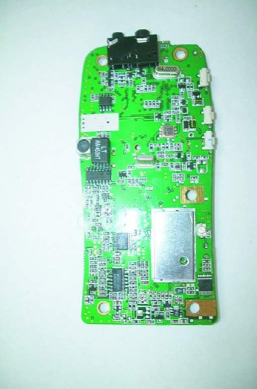
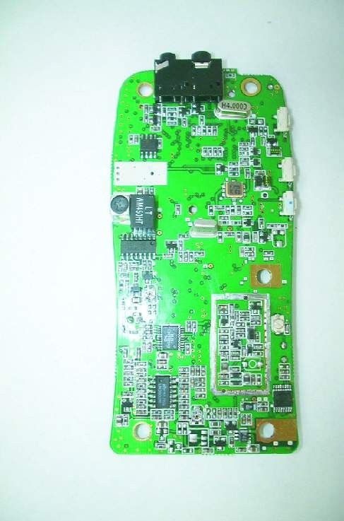
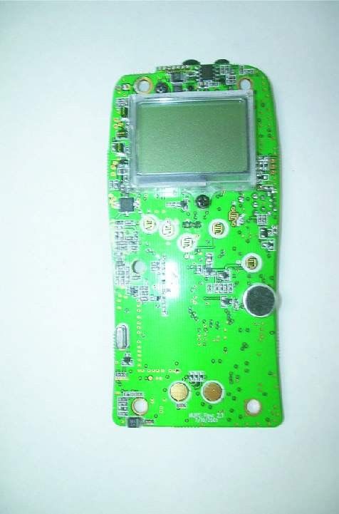
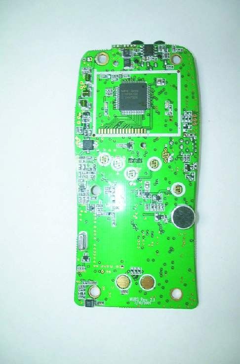
Document Text
Text extracted from the exhibit documents filed with the FCC. Open a document above to read the original.
Users Manual
OPERATION OPERATION OPERATION OPERATION OPERATION OPERATION OPERATION OPERATION
ID Label/Location Info
FCC MARKING/LABEL FOR PART 15 H K PROTECH / HKM1002 FCC ID : PQXHKM 1002 HKP MODEL NUMBER : HKM1002 THIS DEVICE COMPLIES WITH PART 15 OF THE FCC RULES. OPERATION IS SUBJECT TO THE FOLLOWING TWO CONDITIONS : (1) THIS DEVICE MAY NOT CAUSE HARMFUL INTERFERENCE, AND (2) THIS DEVICE MUST ACCEPT ANY INTERFERENCE RECEIVED, INCLUDING INTERFERENCE THAT MAY CAUSE UNDESIRED OPERATION.
Operational Description
4. CIRCUIT DESCRIPTION – 5. Troubleshooting ProblemSolution No PowerRecharge or Replace Battery Message Not receivedMake sure the PTT button is completely pressed as you transmit. Reposition or replace batteries Message Not receivedConfirm transceivers have the same channel and privacy codes settings. Increase Volume level Release PTT Button Reception of unwanted signals Turn on the Codes mode and set code number to match the setting of the target transceiver. Cannot change channel and codes settings Make radio is unlocked. See page for more information. Low batteriesReplace batteries.
Parts List/Tune Up Info
M U R S [HKM-1002] INSTRUCTION MANUAL 2-WAY HANDHELD RADIO 1. GENERAL 1-1 Introduction The HKP Corp. HKM-1002 is MURS handheld tow-way radio VHF transceiver. The transceiver has 5 Channels and 10 weathers. Weather channels can also be accessed immediately by pressing the Function key. The radio is the newest generation in personal two way communications. The radio is a lightweight, compact two way communication device that can be used to communicate with family or friends at parks, shopping malls, sporting events, concerts-any indoor or activity! 1-2 CHARACTERISTIC 1) All active devices in the radio is composed of semiconductor and high density IC. 2) To design the radio in compact and weight approximately 120g with out battery. 3) Mi-com of the radio is Upd789418A by NEC 4) It’s DC supply power can operate by use of alkaline 4 Cell (1.5V AAA) battery. 1-3 COMPOSITION The radio is composed of following. 1) Transceiver (W/Antenna) 2) Belt clip 3) Manual 2. SPECIFICATIONS General Frequency Range 151.820 – 154.600Mhz Channels 5CH Privacy Codes 38 for each main channel Dimensions (W x H x D) 63mm x 120mm x 35mm Power Supply Power Source Alkaline Batteries, AA(4), 6VDC Operating Time 26 Hours (Alkaline Batteries; 5:5:90) 70 Hours ( Standby ) Receiver Useable Sensitivity > -120 dBm Maximum Audio Output Power > 0.3 Watts (8 Ohm) Modulation Distortion < 5% ( 1khz 60% ) SNR 35dB Transmitter RF Output Power High .5 Watt ERP, Low 0.033 Watt ERP Range Up to 5miles Maximum Deviation ± 2.5khz Modulation Distortion < 5% ( 1khz 60% ) SNR 35 dB 3. ADJUSTMENT 3-1. Frequency synthesizer - After connecting the RF power meter and dummy load (50 ohm), join the antenna connector of HP8920 with above equipment. - Check the voltage between TP and GND in digital Voltage meter. - The set low channel(CH1, 151.820Mhz) of HP8920 the lowest frequency. - After pressed PTT key of HP8920, check if the lowest frequency of Tx channel to DC 1.2V in the voltage of test point (VT) - After releasing the PTT key of HP8920, check if the highest frequency (CH5,154.600Mhz) of Rx channel is within DC 1.2V in the voltage of test point (VT). 3-2. Transmitter - Connect the RADIO and measure equipment according to block diagram below. - load) after power on. - Connection method - The Conform of Rx sensitivity 1) Set SSG to 1channel(151.820Mhz) frequency. 2) Adjust modulation frequency, 1khz to modulation degree, 1.5khz. 3) After adjusting the frequency of SSG to channel frequency, RF level sets to –47dBm. - The Conform of Squelch sensitivity 1) Set the standard channel (CH1, 151.820Mhz) 2) In squelch mode, SQ variable resister VR101 must be turned counterclockwise. 3) After adjusting SSG to channel frequency, the RF level of SSG is set On SINAD 12~0dB. 3-5. Receiver Test - Rx sensitivity test SSG should be adjusted to 12dB of SINAD point needle seeing wave of Oscilloscope as SSG sets in 1khz frequency deviation. At this time, normal RF level is –122~-124dBm. - Audio Distortion Test 1) SSG should be adjusted like way of point “Rx sensitivity test” and RF level sets to –47dBm. 2) Adjust to 0.7Vrms (8 load) seeing Audio wave. 3) Read the needle of Distortion Meter (Normal condition would be less then 5% Distortion) - Squelch Test After RF level of SSG should be set to the least
Test Report
Applicant: HK Protech, Inc. FCC ID: PQXHKM1002 Report #: H\HkProteck\529KT2\529KT2TestReport.doc Page #: Table of Contents TABLE OF CONTENTS LIST APPLICANT: HK PROTECH, INC FCC ID: PQXHKM1002 TEST REPORT: PAGE 1......COVER SHEET - GENERAL INFORMATION & TECHNICAL DESCR. PAGE 2......TECHNICAL DESCRIPTION CONTINUED PAGE 3......RF POWER OUTPUT PAGE 4......MODULATION CHARACTERISTICS PAGE 5......AUDIO FREQUENCE RESPONSE PAGE 6......MODULATION LIMITING – 300 Hz PAGE 7......MODULATION LIMITING – 1000 Hz PAGE 8......MODULATION LIMITING – 3000 Hz PAGE 9......AUDIO LOW PASS FILTER GRAPH PAGE 10.....EMISSION BANDWIDTH PAGE 11-13..OCCUPIED BANDWIDTH PLOTS PAGE 14.....METHOD OF MEASURING OCCUPIED BANDWIDTH PAGE 15.....FIELD STRENGTH OF SPURIOUS EMISSIONS PAGE 16.....METHOD OF MEASURING RADIATED SPURIOUS EMISSIONS PAGE 17.....FREQUENCY STABILITY PAGE 18.....MPE CALCULATION PAGE 19-22..LIST OF TEST EQUIPMENT EXHIBITS CONTAINING: EXHIBIT 1.........FCC ID LABEL SAMPLE EXHIBIT 2.........SKETCH OF FCC ID LABEL LOCATION EXHIBIT 3.........EXTERNAL PHOTO - FRONT VIEW EXHIBIT 4.........EXTERNAL PHOTO – REAR VIEW EXHIBIT 5-6.......EXTERNAL PHOTO – SIDE VIEWS EXHIBIT 7.........EXTERNAL PHOTO - TOP VIEW EXHIBIT 8-9.......INTERNAL PHOTO - COMPONENT SIDE EXHIBIT 10-11.....INTERNAL PHOTO - SOLDER SIDE EXHIBIT 12........BLOCK DIAGRAM EXHIBIT 13........SCHEMATIC EXHIBIT 14........USER'S MANUAL EXHIBIT 15........CIRCUIT DESCRIPTION EXHBIIT 16........TUNING PROCEDURE EXHIBIT 17........TEST SETUP PHOTO Applicant: HK Protech, Inc. FCC ID: PQXHKM1002 Report #: H\HkProteck\529KT2\529KT2TestReport.doc Page #: 1 OF 20 GENERAL_INFORMATION_REQUIRED FOR_TYPE_ACCEPTANCE 2.1033(c)(1)(2)HK PROTECH, INC will manufacture the FCC ID: PQXHKM1002 MULTI USER RADIO SERVICE TRANSCEIVER in quantity, for use under FCC RULES PART 95. The UUT is a PTT Radio with a maximum duty cycle of 50%. HK PROTECH, INC 3-10, CHUNGCHUN-DONG, BUPYUNG-GU INCHON, KOREA 2.1033 (c) TECHNICAL_DESCRIPTION 2.1033(c)(3) Instruction book. A draft copy of the instruction manual is included as EXHIBIT 14. 2.1033(c) (4) Type of Emission: 10K0F3E 95.632 Bn = 2M + 2DK M = 3000 D = 2.0K Bn = 2(3.0)+2(2.0) = 10.0K Authorized Bandwidth – 11.25 kHz for frequencies: 151.820, 151.880, 151.940 MHz Authorized Bandwidth - 12.5 kHz for frequencies: 154.570, 154.600 MHz 2.1033(c)(5) Frequency Range: 1. 151.820 95.632 2. 151.880 3. 151.940 4. 154.570 5. 154.600 2.1033(c)(6)(7) Power Output shall not exceed 2.0 Watts effective 95.639 radiated power. There can be no provisions for 95.649 increasing the power or varing the power. The antenna is an intergral part to the unit, it cannot be removed without rendering the unit inoperative. In order to remove the antenna the case must unscrewed, then the PCB assemblies must be removed then the antenna can be removed. Applicant: HK Protech, Inc. FCC ID: PQXHKM1002 Report #: H\HkProteck\529KT2\529KT2TestReport.doc Page #: 2 OF 20 2.1033(c)(9) Tune-up procedure. The tune-up procedure is included in the IN EXHIBIT 16. 2.1033(c)(8) DC Voltages and Current into Final Amplifier: FINAL AMPLIFIER ONLY High - Vce = 6.0 Volts DC Ice = 0.44A Pin = 2.64 Watts Low - Vce = 6.0 Volts DC Ice = 0.44A Pin = 2.64 Watts 2.1033(c)(10) Complete Circuit Diagrams: The circuit diagram is included as EXHIBIT 13 of this report. The block diagram is included as EXHIBIT 12 of this report. 2.1033(c)(11) A photograph or a drawing of the equipment identification label is included as exhibit No. 1. 2.1033(c)(12) Photographs(8"X10") of the equipment of sufficient clarity to reveal equipment construction and layout, including meters, labels for controls, including any view under shields - See EXHIBIT 3-11. 2.1033(c)(13) Digital modulation is not not used in this device. 2.1033(c)(14) The data required by 2.1046 through 2.1057 is submitted below. Applicant: HK Protech, Inc. FCC ID: PQXHKM1002 Report #: H\HkProteck\529KT2\529KT2TestReport.doc Page #: 3 OF 22 2.1046(a) RF_power_output. 95.639(g) RF power is measured by measuring the radiated power at 3 meters and then replacing the transmitter with a signal generator to determine the effective radiated power. The ERP shall not exceed 2.0 Watts. MEASURED POWER OUTPUT = 0.5 Watts ERP HIGH POWER .033 Watts ERP LOW POWER R.F. POWER OUTPUT HP TEST SET UP Spectrum Analyzer TRANSMITTER UNDER TEST WITH INTERNAL ANTENNA <-- 3.0 meters---> SIGNAL DIPOLE Tuned, Calibrated GENERATOR ANTENNA Antenna which may be raised from 1 to 4 meters above ground and changed in polarization Equipment placed 80cm above ground on a rotatable platform. Applicant: HK Protech, Inc. FCC ID: PQXHKM1002 Report #: H\HkProteck\529KT2\529KT2TestReport.doc Page #: 4 OF 22 2.1047(a)(b) Modulation characteristics: AUDIO FREQUENCY RESPONSE The audio frequency response was measured in ac- cordance with TIA/EIA Specification 603. The audio frequency response curve is shown on the next page. The audio signal was fed into a dummy microphone circuit and into the microphone connector. The input required to produce 30 percent modulation level was measured. See Page 5 of report. 2.1047(b) Audio input versus modulation The audio input level needed for a particular per- percentage of modulation was measured in accor- dance with TIA/EIA Specification 603. The audio input curves versus modulation are on the following pages. Curves are provided for audio input frequen- cies of 300, 1000, and 3000 Hz. See Pages 6,7 & 8 of report. 95.637 Post Limiter Filter Each GMRS transmitter, except a mobile station transmitter with a power of 2.5Watts or less, must be equipped with an audio low pass filter. At any frequency between 3 & 20 kHz the filter must have an attenuation of 60log (f/3) greater than the attenuation at 1KHz. See Page 9 of report. Applicant: HK Protech, Inc. FCC ID: PQXHKM1002 Report #: H\HkProteck\529KT2\529KT2TestReport.doc Page #: 5 OF 22 AUDIO FREQUENCY RESPONSE PLOT HK Protech Inc. HKM 1002 -55 -53 -51 -49 -47 -45 -43 -41 -39 -37 -35 100100010000 Frequency dBmV audio respo…
Text truncated - open the document above for the full version.
Contact Information
Applicant
Young C Choy(Vice President)
Technical Contact
Timco Engineering, Inc.Mario R de Aranzeta
[email protected]888-472-2424
849 N.W. State Road · Newberry, Florida · United States
Non-Technical Contact
Timco Engineering, Inc.Sharon A Hoffman
[email protected]888-472-2424
Test Firm
Timco Engineering, Inc.S Sanders
Technical Specifications
| # | Rule Parts | Frequency Range | Power Output | Emission | Tolerance |
|---|---|---|---|---|---|
| 2 | 95J | 151.82 MHz - 154.6 MHz | 33.00 mW | 10K0F3E | 5 ppm |
Other Applications from H K Protech, Inc.
PQXHKG2003
Jan 30, 2002GMRS
Equipment Class
TNF - Licensed Non-Broadcast Transmitter Held to Face