PR6MB1Digital Wireless Microphone
Zaxcom, Inc.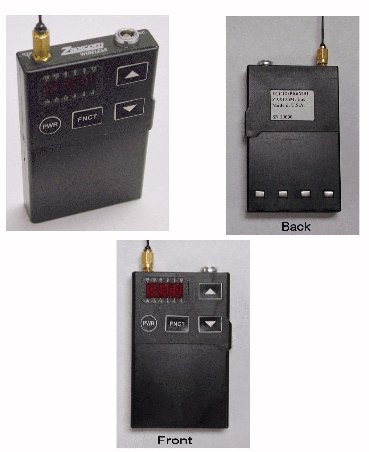
Click to zoom
Application Details
- Equipment Class
- TBT - Licensed Broadcast Transmitter Worn on Body
- Date of Grant
- Oct 29, 2001
- Application Purpose
- Original Equipment
- Date of Application
- Oct 29, 2001
- Equipment Note
- Digital Wireless Microphone
- Frequency Range
- 470.00000000 - 952.00000000
- Company
- Zaxcom, Inc.
- Country
- United States
Documents & Files
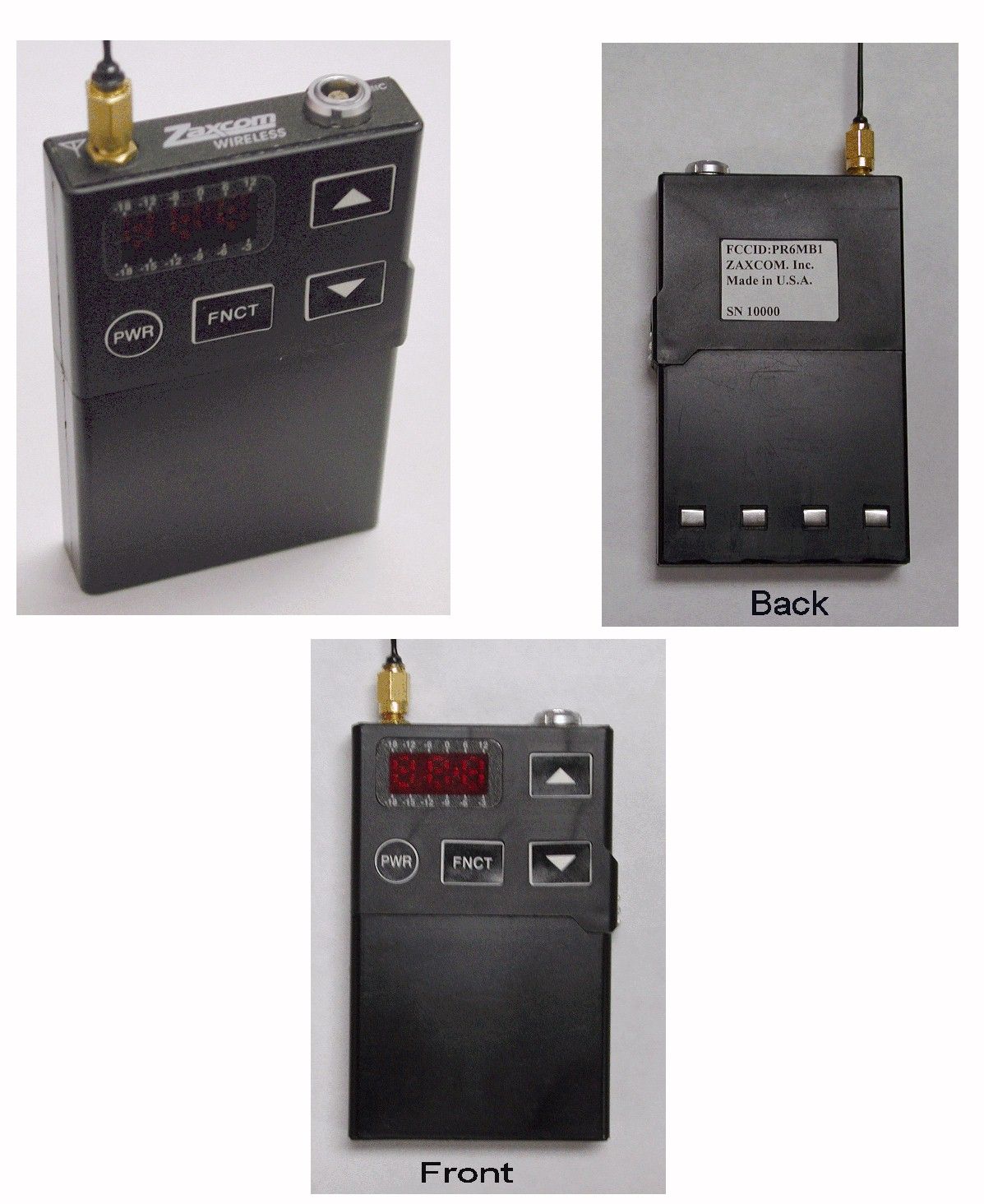
Document Text
Text extracted from the exhibit documents filed with the FCC. Open a document above to read the original.
Users Manual
Revision 0: Initial Draft Copy: Confidential Zaxcom Inc. 140 Greenwood Ave, Bldg #2 Midland Park, NJ 07432 MB1 Digital Wireless Microphone Transmitter Instruction Manual Zaxcom Inc. www.Zaxcom.com Zaxcom Transmitter Operating Instructions Initial draft copy The external connections on the MB1 transmitter consist of a 4 pin microphone connector and an SSMA antenna connector. Only use the proper antenna and microphone supplied by Zaxcom. Do not operate the transmitter without the antenna. When mounting the transmitter be sure to always leave at least 2.5 cm clearance between the antenna and any other objects. The user interface for the transmitter consists of 3 LED digits and 4 buttons: PWR = Power on/off: Hold this key for 3 seconds to turn the transmitter on or off. FNCT = Function/menu page select: Press to cycle through each menu page. INC = Increment the current parameter selected by the FNCT key. DEC = Decrement the current parameter selected by the FNCT key. BATTERY The battery module consists of a 4 Volt Lithium Ion rechargeable battery. The battery slides on from left to right and snaps in place. In order to remove the battery module, firmly slide the silver battery release up and then slide the battery to the left. Nominal operating voltage: 3.8 volts at 320 milliamps Maximum RF output power: 50 milliWatts Antenna impedance: 50 Ohms When the battery is in place, the unit will boot up in about 2 seconds. The display will default to a pacifier mode where the INC and DEC keys have no function and a single center LED segment stripes across the screen every second. If this display does not come up after the battery has been installed, check to be sure the battery is fully charged. The battery must supply between 3.4 and 4.5 volts for the transmitter to operate properly. If the battery voltage falls below 3.3 volts the transmitter will partially power down in a reset mode. To prevent permanent damage to the battery, do not leave the battery in place so that it fully discharges. Transmitter Menu Pages The Transmitter has a few menu pages which allow the user to change various settings. Note that the transmitter will reset all of its settings back to factory default when powered up. PACIFIER PAGE At power-up the transmitter will display a pacifier page. The INC and DEC keys have no functionality in this page. AUDIO GAIN PAGE Press the FNCT key once and the LEDs will go blank. When audio is applied to the microphone input the LEDs will display the audio level. The mic preamp gain may be adjusted in this page by pressing the INC or DEC keys repeatedly. The mic gain is set to maximum at boot up and should provide normal operation at this setting. CHANNEL SELECT PAGE Press the FNCT key again to display the Channel Select page. This page will display the current channel code. To change channels press the INC and DEC keys. The transmitter will operate at 1 of the 16 channels (spaced 1.920 MHz) as shown below: Center = 652.32 MHz 636.96 = channel 0 638.88 = channel 1 640.80 = channel 2 642.72 = channel 3 644.64 = channel 4 646.56 = channel 5 648.48 = channel 6 650.40 = channel 7 652.32 = channel 8 654.24 = channel 9 656.16 = channel A 658.08 = channel B 660.00 = channel C 661.92 = channel D 663.84 = channel E 665.76 = channel F TONE and ID CODE SELECT PAGE This page allows the user to cause a 2 kHz sine wave to be transmitted instead of normal microphone audio. The transmitter boots up in TONE=OFF as its default mode. Press the INC key and then the DEC key to turn off the test tone. Zaxcom Battery Charger Operating Instructions The battery charger runs from about 12 Volts at 1.5 amps when in rapid-charge mode. Place a battery in the slot and the green LED should light. In a few seconds, the yellow LED should light indicating the battery is in high-current charge mode. When the battery is done charging all LEDs should go off. The transmitter batteries will last about 4 hours when fully charged. Be sure to remove the batteries from the transmitter before they become completely discharged to prevent damage to the battery.
Cover Letter(s)
October 21, 2001 Applicant: Zaxcom, Inc. 140 Greenwood Ave. Midland Park NJ 07432 Glenn Sanders President Re: Confidentiality for schematics Equipment: FCC ID:PR6MB1 FCC Rules: Part2 and 74 Gentlemen: Zaxcom Inc. requests that the material in the schematic diagrams, functional description and circuit board photographs be withheld from public disclosure in accordance with Section 0.459 of the Commissions Rules, 47 CFR 0.459, following the grant of certification. In support of this request, Zaxcom Inc. submits the following: 1. Identification of the specific information for which confidential treatment is sought: The materials set forth in the schematic diagrams, functional description and circuit board photographs which are segregated from the non-confidential exhibits of the application, are those for which confidentiality is sought. 2. Identification of the Commission proceeding in which the information was submitted or a description of the circumstances giving rise to the submission: The proceeding is that involving the application for equipment authorization (certification) under FCC ID number PR6MB1. 3. An explanation of the degree to which the information is commercial or financial, or contains trade secrete or is privileged: This material includes a detailed schematic of the device functional description and circuit board photographs. As such this material is treated as highly confidential business information. 4. Explanation of the degree to which the information concerns a service that is subject to competition: The material for which confidentiality is ought is employed in the design and manufacture of wireless microphone systems transmitting equipment that is offered on a highly competitive basis. Customers for this equipment have a variety of competing sources. 5. Explanation of how disclosure of this information could result in substantial competitive harm: Disclosure would, in effect, give away the fruits of the labors of Zaxcom Inc. ' s engineering department and personnel, who have designed the equipment and manufacturing process. Disclosure would also offer competitors additional unwarranted insight into the state of the product development, thereby allowing competitors an advantage, not available to Zaxcom Inc. Substantial development effort and cost was applied to the physical placement of components in this product to prevent unintended radiation and internal interference. Knowledge of this component placement information would greatly reduce the burden of a competitor attempting to create a competing product. 6. Identification of any measures taken by the submitting party to prevent unauthorized disclosure: The information for which confidential treatment is ought is kept confidential by Zaxcom Inc. and not made available to third parties except pursuant to non-disclosure agreements. The product is sealed closed during the final manufacturing process. In order to gain access to the internal PC boards the unit would likely be permanently damaged. 7. Identification of whether the information is available to the public and the extent of any previous disclosure of the information to third parties: To the knowledge of those preparing this application, the informaton has not been disclosed publicly heretofore. While the general theory of operation of this equipment has been the subject of numerous disclosures in industry and standards groups as well as in the rule making proceedings of the FCC, the protection sought is narrowly drawn and pertains to certain specific implementations of the digital modulation technology. 8. Justification of the period during which the submitting party asserts that the material should not be available for public disclosure: This material should not be disclosed for at least 25 years. While improvements in the design are made relatively frequently, disclosure of the design information would lead to insights into both design and manufacturng techniques that could have an adverse competitive effect for many years to come. This equipment is designed for commercial, industrial and govemmental applications. As such, unlike most consumer equipment, this equipment will be used for more than a decade in most cases. As such, it is important that the design not be made available to unauthorized persons who might attempt to use knowledge of the design to compromise the applications for which the equipment will be employed. 9. Any other information that the party seeking confidential treatment believes may be useful in assessing whether its request for confidentiality should be granted: See item 8 above. Note that the equipment for which approval is being sought will be employed in applications that inherently place a premeium on security. Zaxcom is a small company compared to its competitors in this market. It has invested a large sum of money and 3 years of development in this product. As this is a new market for Zaxcom products, it will be difficult to establish this product in the marketplace unless it has unique advantages. There are unique electrical as well as mechanical aspects of this design. Any information that can be easily obtained by our competitors will cause extreme harm to Zaxcom’s ability to penetrate this new market with a unique product. The design of this product is unique as the data transmission rate is up to three times as fast as the competition and the physical size is half that of the competition. Both factors are of extreme importance to the customer base. The electrical and internal physical characteristics of the printed circuit boards are critical in achieving this competitive advantage. The special fee for request of confidentiality will be submitted with the application. Should you require any further information, please contact the undersigned. Thank you for your consideration in this matter. Sincerely, GLENN SANDERS Zaxcom Inc.
Cover Letter(s)
C:\windows\TEMP\probonholdemail.doc TIMCO TIMCOTIMCO TIMCO ENGINEERING INC. 849 NW State Road 45 Newberry, Florida 32669 http://www.timcoengr.com 888.472.2424 F 352.472.2030 email: tei@t imcoengr.com October 30, 2001 FCC SUBJECT: ZAXCOM, INC. FCC ID: PR6MB1 REFERENCE: JOB #:1085U1 To those concerned: The confidentiality request, specifically for the internal photos, was forwarded to and approved by the commission on 10/26/01. Further details may be provided upon request. Regards, Eric Dobson Timco Engineering, Inc.
ID Label/Location Info
FCC label is located on back of unit in center.
Parts List/Tune Up Info
MB1 Transmitter Tune-up Procedure Equipment Required RF spectrum analyzer with sensitivity of –100 dBm or better, frequency range of 10 MHz to 3 GHz or wider, capable of non-distorted +20 dBm input. Capable of measuring occupied bandwidth and power output. Device used in development: Rohde & Schwarz FSEA 3.5 GHz spectrum analyzer Current limiting power supply capable of supplying 400 mA at 4 Volts with an accuracy of 3% or better. Device used in development: HP 6112A Test Accessories 2 feet of 50 Ohm flexible coaxial cable. The cable should be terminated with a mating connector for the spectrum analyzer and with an SSMA male connector for mating to the transmitter under test. The cable should have its loss characteristics measured (about 1 dB) and all power measurements should compensate for this loss. 50 Ohm, 10 dB Attenuator pad. Non-ferrous tuning tool appropriate for tuning surface-mount variable capacitors. Battery eliminator module for applying power to the unit under test. Electrically conductive tweezers for entering calibration mode. Note that this procedure is performed on the PCBs when they are removed from their enclosure and is accessible only to Zaxcom employees. RF Tuning All RF tuning adjustments are made on the TX-RF PCB board. Apply power to the transmitter using the battery eliminator module. Set the external power supply to 3.8 Volts current limited at 400 mA. Observe that the transmitter passes its self-diagnostic tests. Setup the Rohde & Schwarz FSEA 3.5 GHz spectrum analyzer to the following settings: Start Frequency = 1 MHz Stop Frequency = 3.5 GHz Resolution bandwidth = 300 kHz Using the front panel user interface of the transmitter under test, tune the transmitter to the center of its tuning range. Connect the antenna output of the device under test to the spectrum analyzer through a 50 ohm 10 dB attenuator. Tune C207 to produce maximum amplitude carrier. Tune C300 to produce maximum power output. Alternately tune C73 and C120 to produce maximum power output at the fundamental frequency. Tune C399 such that the 2nd harmonic is minimized. Observe the output of the transmitter to ensure power output is close to 50 mW (+/- 1 dB). Repeat entire procedure. Set the spectrum analyzer to 99% occupied bandwidth mode and ensure that the occupied bandwidth is less than 180 kHz. Adjust transmitter to its lowest and highest operating frequencies. Ensure that all harmonics are suppressed at least 45 dB with respect to the fundamental output frequency at both minimum and maximum possible operating frequencies. IQ Calibration Using the metallic tweezers, short the resistor (R113) on the TX-DSP board to enable IQ calibration mode. On the front panel interface, choose the "Cal I" menu. Repeatedly press INC or DEC to minimize the carrier output. Choose the "CAL Q" menu and repeat. Repeat procedure for both Q and I until minimum possible carrier is obtained. Hold the FNCT key for 3 seconds until display flashes to indicate settings have been stored in FLASH ROM.
Test Report
TEST REPORT FOR ZAXCOM INC. MODEL MB-1 WIRELESS MICROPHONE For Zaxcom Inc. 140 Greenwood Ave Midland Park NJ 07432 Glenn Sanders President Model: MB1 Name: Digital Wireless Microphone Transmitter Frequency 470-802 MHz FCC ID: PR6MB1 Test Date October 16 2001 EXHIBIT 1:............................................................................................................................................3 Forward:.............................................................................................................................................3 2.1033 Application for certification:................................................................................................3 List Of Test Instrumentation................................................................................................................5 2.1046 RF Power Output.....................................................................................................................5 Measurements Required:.................................................................................................................5 Test Arrangement:...........................................................................................................................5 Measurement Results:......................................................................................................................6 2.1047 Modulation Characteristics....................................................................................................7 Measurements Required:.................................................................................................................7 Test Arrangement:...........................................................................................................................7 Results:............................................................................................................................................7 2.1049 Occupied Bandwidth..............................................................................................................7 Measurements Required:.................................................................................................................7 Test Arrangement:...........................................................................................................................7 Results:............................................................................................................................................8 2.1051 Spurious Emissions at Antenna Terminals..............................................................................9 Measurements required:...................................................................................................................9 Test Arrangement:...........................................................................................................................9 Results:..........................................................................................................................................10 2.1053 Field Strength of Spurious Radiation...................................................................................10 Measurements Required:...............................................................................................................10 Test Arrangement:.........................................................................................................................10 Results:..........................................................................................................................................11 2.1055 Frequency Stability................................................................................................................14 Test Arrangement for Power Voltage Stability:..............................................................................14 Measurements required:.................................................................................................................14 Measurement Results:....................................................................................................................15 Test Arrangement for Temperature Stability:.................................................................................15 Measurement Results:....................................................................................................................16 EXHIBIT II...........................................................................................................................................17 Appendix ........................................................................................................................................17 MB1 Transmitter Tune-up Procedure ...............................................................................................17 Equipment Required ..........................................................................................................................17 Test Accessories............................................................................................................................17 RF Tuning ............................................................................................................................................17 IQ Calibration.......................................................................................................................................18 EXHIBIT 1: Forward: In accordance with the Federal Communications Code of Federal Regulations, dated October 1, 1999, Part 2 Subpart J, Paragraphs 2.907, 2.911 to 2.913, 2.925, 2.926, 2.1031 through 2.1057 and; Part 74 Subpart H; Paragraphs 74.801 through 74.861 the following is submitted: 2.1033 Application for certification: According to section 2.1033 the following exhibits are required: (1) Name and Address: Zaxcom Inc. 140 Greenwood Ave, BLDG. #2 Midland Park, NJ 07432 (2) FCC Identifier: PR6MB1 (3) Manual/instructi…
Text truncated - open the document above for the full version.
Contact Information
Applicant
Glenn Sanders(President)
Test Firm
Global Certification Laboratory LtdSteve Petix
Technical Specifications
| # | Rule Parts | Frequency Range | Power Output | Emission | Tolerance |
|---|---|---|---|---|---|
| 1 | 74.861 | 470 MHz - 952 MHz | 50.00 mW | 180KV2E | 0.0010000000 % |
Other Applications from Zaxcom, Inc.
PR6VTX
Jan 16, 2025VHF IFB Transmitter
Equipment Class
TLD - Licensed LPAS Device
PR6TRX
Jul 10, 2006TRANSCEIVER
Equipment Class
TNT - Licensed Non-Broadcast Transmitter Worn on Body