PR6TRXTRANSCEIVER
Zaxcom, Inc.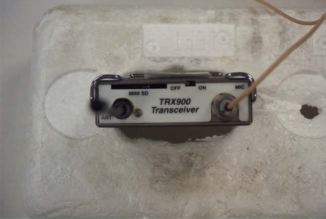
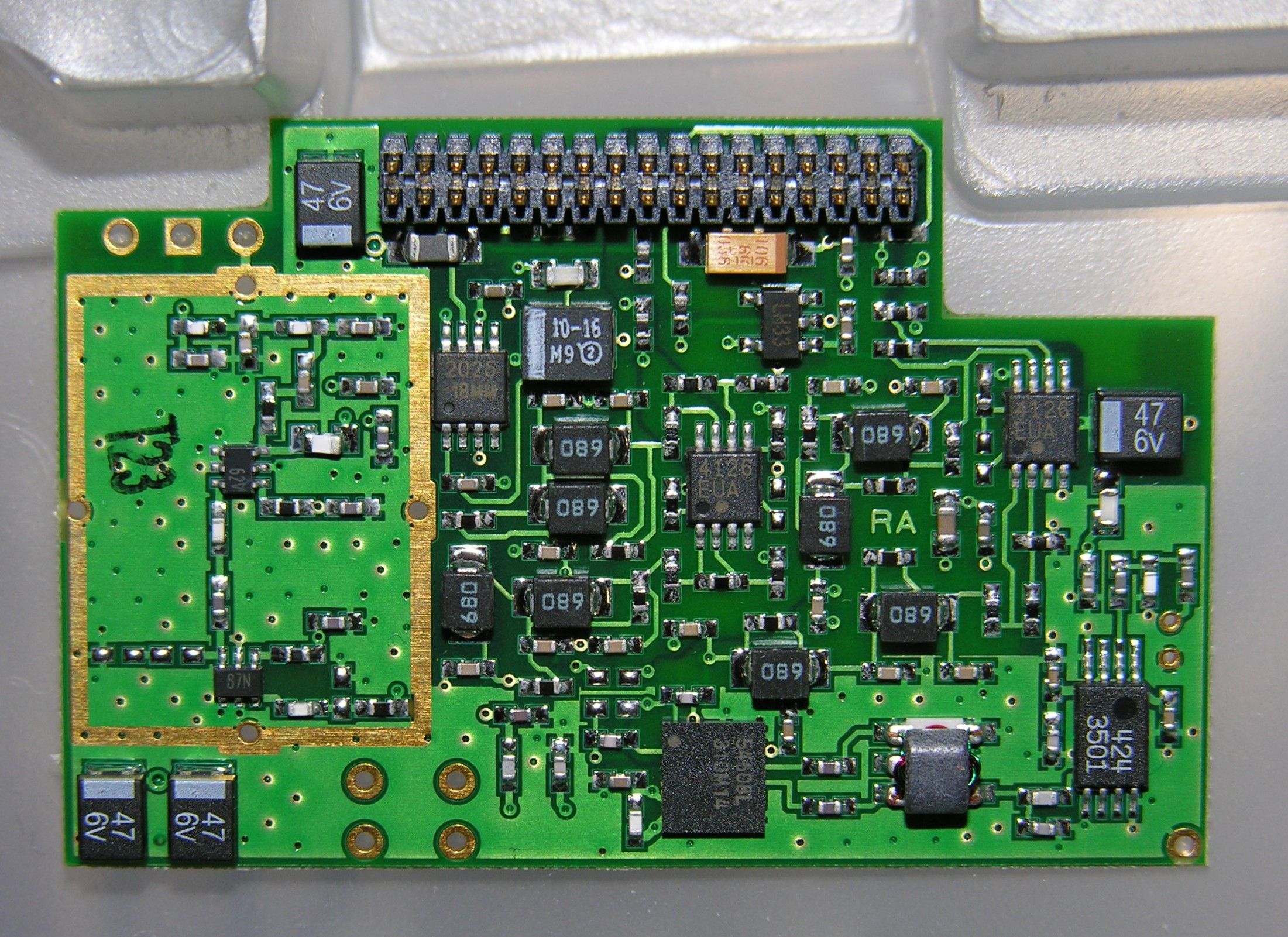
Click to zoom
Application Details
- Equipment Class
- TNT - Licensed Non-Broadcast Transmitter Worn on Body
- Date of Grant
- Jul 10, 2006
- Application Purpose
- Original Equipment
- Date of Application
- Jul 10, 2006
- Equipment Note
- TRANSCEIVER
- Frequency Range
- 662.00000000 - 686.00000000
- Company
- Zaxcom, Inc.
- Country
- United States
Documents & Files
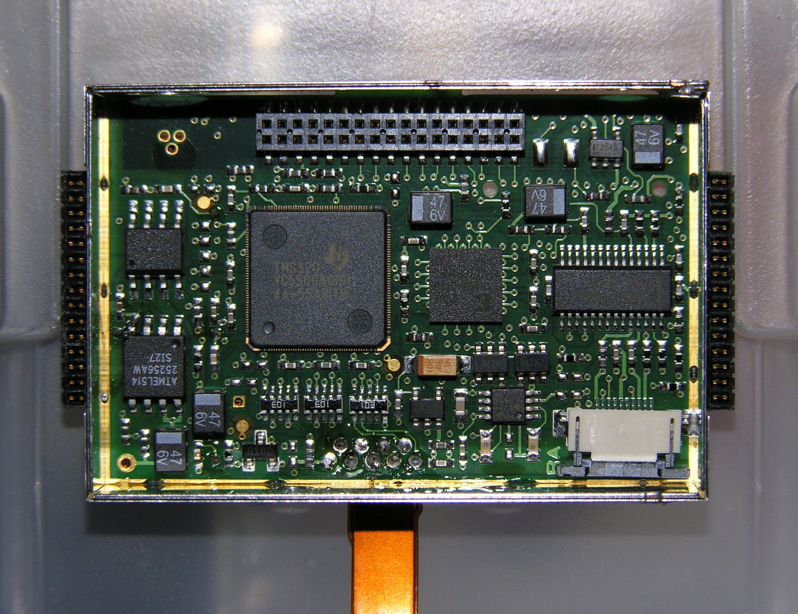
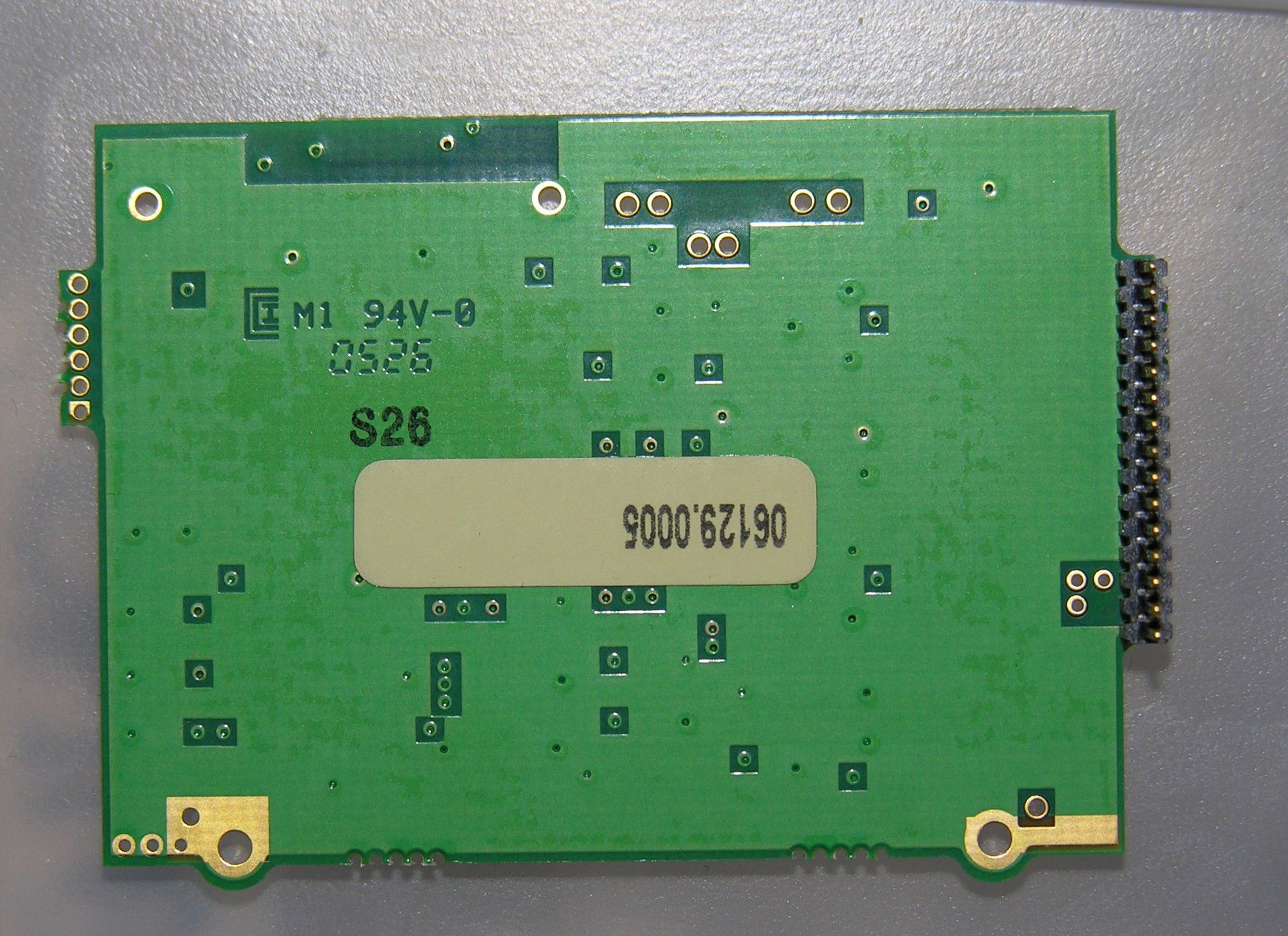
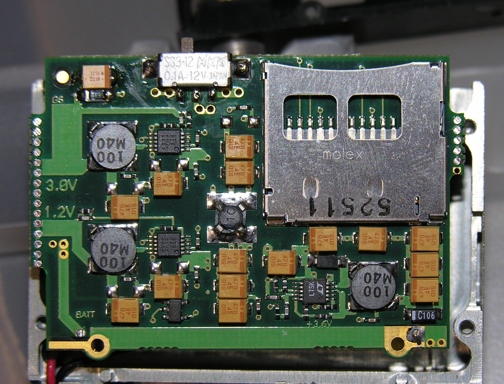
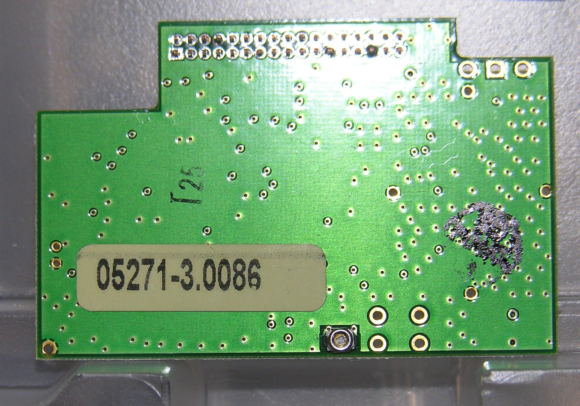
Document Text
Text extracted from the exhibit documents filed with the FCC. Open a document above to read the original.
Users Manual
Zaxcom TRX900/900AA Transmitter Guide Zaxcom Inc. 230 West Parkway, Unit 9, Pompton Plains, NJ 07444 - 973-835-5000 Document Revision 1.02 For Firmware Revision 33 and Higher This guide assumes the firmware version displayed above is installed. The firmware revision code is displayed shortly every time the transmitter is turned on. Important Note for TRX900AA Wireless Transmitters: Only Lithium or rechargeable NiMH should be used in these models. Any other battery chemistry (including Alkaline and “Ultra” batteries) will have a substantially reduced run-time compared to Lithium or rechargeable NiMH cells. This is true for all Zaxcom transmitter models that accept AA batteries. Never use any battery that is missing insulation on its body. This can allow a short circuit in the battery compartment causing damage to the transmitter. TRX900 Power up Install 1 CR123 battery into the TRX900 transmitter. Install 2 AA batteries into the TRX900AA Close the battery door. Be sure to install the batteries with the correct polarity. Damage to the unit may result if the batteries are installed backwards. The negative contact always connects to the spring contact. For maximum transmitter time use Energizer Lithium batteries. This should give a transmitter time of 10 hours for TRX900AA (5 hours TRX900) . On power up the transmitter will display the version number of the software in the top right corner of the display. The power switch is located on the top of the transmitter. Slide it to the on position to turn on the unit. Transmitter Menu System The user interface for the transmitter consists of a graphic LCD display and 3 buttons: MENU = Function/menu page select: Press to cycle through each menu page. UP/INC = Increment the current parameter selected by the MENU key. DOWN/DEC = Decrement the current parameter selected by the MENU key. The transmitter has a few menu pages that allow the user to change various settings. Note that the transmitter will store the user's settings in FLASH ROM when power is removed. There is no secondary memory battery so the settings will always remain secure without any power. The available menu pages are summarized below. PACIFIER PAGE: Indicates TX frequency battery level and record mode. AUDIO GAIN PAGE: Allows user to change the mic preamp gain. TXCHANNEL SELECT PAGE: Selects TX channel center frequency. RXCHANNEL SELECT PAGE: Selects RX channel center frequency. LOCK MODE PAGE: Staying here locks out key presses. MENU+INC exits lock mode. The last seven menu pages are infrequently used special functions. In order to get to those pages the MENU key must be held while powering up the transmitter. To exit this special menu system cycle power off then back on. ID CODE #0 SELECT PAGE: Changes the security0 code (normally should be set to zero) ID CODE #1 SELECT PAGE: Changes the security1 code (normally should be set to zero) FORMAT SELECT PAGE: Changes the transmission data format HIGH-PASS FILTER PAGE: Changes the cutoff frequency of the high-pass filter Limiter ON/OFF PAGE: Changes the peak limiter state Group SELECT PAGE: Changes the selection of a control group for remote control UNIT SELECT PAGE: Changes the unit ID code for remote control TEXT NAME PAGE Allows entry of Text identification metadata for file output POWER UP LOCK/UNLOCK Selects the lock mode on power up Repeatedly press the FNCT key to cycle through the following menu pages. PACIFIER PAGE At power-up the transmitter will enter the home pacifier page. The UP and DOWN keys have no function in this page. In this page the unit will display the Txfrequency, battery level and the mode of the recording. AUDIO GAIN PAGE(s) This page is indicated by the word GAIN on the left side of the display. The two-digit number indicates the gain setting of the mic preamp. When audio is applied to the microphone input the LCD will display the audio level. The mic preamp gain may be adjusted in this page by pressing the INC or DEC keys repeatedly. Unless a microphone is connected to the unit's input the display will go blank but stay in the gain setting mode. If a significant audio signal is present, the display will meter the signal level horizontally from left to right, from -40 dB to 0 dB. As you speak into the microphone, you can raise and lower the gain with the UP key and the DOWN key. The gain is adjusted in increments of 2 dB. One of the key features of the unit is a digitally controlled analog limiter located before the A/D converter. This means that the digital signal processor can automatically turn down the mic preamp gain when excessive audio is detected to prevent clipping of the A/D converter. This compressor/limiter will engage before signal exceeds the digital capabilities of the signal path. The compressor/limiter will activate at about 6 dB from clipping digital clipping would occur at 0 dB). The gain level should be set low enough so the compressor/limiter does not engage even when the talent is shouting. This gain setting will remain intact even when the battery is removed. TX CHANNEL SELECT PAGE This page will display the current TX channel . To change channels, press the UP and DOWN keys. The TX channel is displayed directly in MHz. Changing the channel will prevent the transmitter from transmitting for 1 second. This allows the user to change channels without transmitting over every single channel that is encountered while obtaining the desired destination channel frequency. If the channel is changed quickly the transmitter will remain quiet until the desired channel has been selected. When operating multiple transmitters in the same location it is recommended that a channel spacing of at least 1 MHz be maintained. If channel frequencies are difficult to obtain the minimum channel spacing can be as low as .7 MHz when set to US modulation or .5 MHz when set to European modulation. The transmitters allow a channel frequency to be chosen anywhere in a 30 MHz range. Utilizing a large channel spread betw…
Text truncated - open the document above for the full version.
Cover Letter(s)
Federal Communications Commission Authorization and Evaluation Division Confidentiality Request regarding application for certification of FCC ID: PR6TRX. Pursuant to Sections 0.457 and 0.459 of the Commission’s Rules, we hereby request confidential treatment of information accompanying this application as outlined below: • Block Diagram • Schematics • Parts List • Tuning Up procedure • Circuit Description The above materials contain trade secrets and proprietary information not customarily released to the public. The public disclosure of these materials may be harmful to the applicant and provide unjustified benefits to its competitors. The applicant understands that pursuant to Section 0.457 of the Rules, disclosure of this application and all accompanying documentation will not be made before the date of the Grant for this application. Sincerely, Glenn Sanders 230 West Parkway, Unit 9, Pompton Plains, NJ 07444 Phone: 973-835-5000 Fax: 973-835-6633 Web Site: http://www.zaxcom.com
ID Label/Location Info
Proposed FCC Label Location – Back Side of EUT FCC ID: PR6TRX
Test Report
FCC PART 74 TEST REPORT Applicant: Zaxcom Inc. Address: 230 West Parkway Unit 9 Pompton Plains, NJ 07444 Contact: Glenn Sanders Title: President FCC ID: PR6TRX Model: TRX900, TRX900AA Trade Name: N/A Product Description: Wireless Microphone Frequency: 662 – 686 MHz Test Date: May 10, 2006 Report Date: May 18, 2006 Approved By: Glenn Sanders TABLE OF CONTENT EXECUTIVE SUMMARY ............................................................................................................ 3 LIST OF TEST INSTRUMENTATION ........................................................................................ 5 2.1046 RF POWER OUTPUT ........................................................................................................ 6 2.1047 MODULATION CHARACTERISTICS .......................................................................... 10 2.1051 SPURIOUS EMISSIONS AT ANTENNA TERMINALS............................................... 16 2.1053 FIELD STRENGTH OF SPURIOUS RADIATION........................................................ 20 2.1055 FREQUENCY STABILITY ............................................................................................. 21 EXECUTIVE SUMMARY Forward In accordance with the Federal Communications Code of Federal Regulations, dated October 1, 1999, Part 2 Subpart J, Paragraphs 2.907, 2.911 to 2.913, 2.925, 2.926, 2.1031 through 2.1057 and; Part 74 Subpart H; Paragraphs 74.801 through 74.861 the following is submitted: 2.1033 Application for certification: According to section 2.1033 the following exhibits are required: (1) Name and Address: Zaxcom Inc. 140 Greenwood Ave, BLDG. #2 Midland Park, NJ 07432 (2) FCC Identifier: PR6TRX (3) Manual/instructions: See the Operating manual in a separate exhibit. (4) Type of Emissions: 180K D2E (5) Frequency range: 662 MHz to 686 MHz with lockout provisions on restricted frequency bands (6) Range of operating power values or specific operating power levels and description of any means provided for varying the output power: The output power is fixed at 34 mW nominal. The transmitter has no provision for operator variation of the output power. (7) The maximum power rating as defined in the applicable part(s) of the rules. As stated in CRF 47, 74.861 (e) (ii), the maximum permissible output power is 250 mW (8) The DC voltages applied to and DC currents into the several elements of the final radio frequency amplifying device for normal operation over the power range. The final amplification stage operates at 3.8 Volts and draws 100 mA for a power requirement of 380mW. (9) Tune-up procedure over the power range, or at specific operating power levels. See tune-up procedure in the Appendix of this document. (10) A schematic diagram and a description of all circuitry and devices provided for determining and stabilizing frequency, for suppression of spurious radiation, for limiting modulation, and for limiting power. See schematics supplied with in a separate exhibit. (11) A photograph or drawing of the equipment identification plate or label showing the information to be placed thereon. See FCC ID label supplied in the photo exhibit supplied with this application. (12) Photographs (8"x10") of the equipment of sufficient clarity to reveal equipment construction and layout, including meters, if any, and labels for controls and meters and sufficient views of the internal construction to define component placement and chassis assembly. Insofar as these requirements are met by photographs or drawings contained in instruction manuals supplied with the certification request, additional photographs are necessary only to complete the required showing. See the photo section in photo exhibit supplied with this application. (13) For equipment employing digital modulation techniques, a detailed description of the modulation system to be used, including the response characteristics (frequency, phase and amplitude) of any filters provided, and a description of the modulating wave train, shall be submitted for the maximum rated conditions under which the equipment will be operated. See the appendix at the end of this document for details. (14) The data required by § 2.1046 through 2.1057, inclusive, measured in accordance with the procedures set out in § 2.1041. LIST OF TEST INSTRUMENTATION The following instrumentation is used in the measurement of emissions. All test equipment calibration is N.I.S.T. traceable. Manufacturer Description Model Serial Number ADVANTEST Spectrum Analyzer R3361A 91730394 AILTECH Log Periodic Antenna 90005 3146 1095 EMCO Horn Antenna 3115 2498 FLUKE Digital Multimeter 76 6540398 GLOBAL Laboratories 3, 10 & 30 meter O.A.T.S. N/A N/A RAYPROOF Shielded Room 4536 Rohde & Schwarz FSEA 3.5 GHz spectrum analyzer FSEA 3 843263/003 SCHWARZBECK Biconical Antenna VHA-9103 “A” SCHWARZBECK RF Receiver 30 to 1000 MHz VUME 1520 1520427 Hewlett Packard Spectrum Analyzer 8569B 37974 2.1046 RF POWER OUTPUT Measurements Required Measurements shall be made to establish the radio frequency power delivered by the transmitter into the standard output termination. The power output shall be monitored and recorded and no adjustment shall be made to the transmitter after the test has begun except as noted below: If the power output is adjustable measurements shall be made for the highest and lowest power levels. Test Arrangement Transmitter -- --> Spectrum Analyzer The RF output power of the transmitter was measured at the antenna output directly with a Rohde & Schwarz FSEA 3.5 GHz spectrum analyzer. The input to the spectrum analyzer had an impedance of 50 ohms, which matched the transmitter's antenna terminal. The power data was read in dBm and converted to watts as shown below. See Table 1 and Figure 1, which show the output power measurements. Data was accumulated as per 2.1046(a) and applicable paragraphs of Part 74. P dBm = Power in dBm = Power in dB above 1 milliwatt milliwatts = 10 ^ (PdBm/10) dBm = 10 (/10) = mW mW * (1 Watt / 1000mW…
Text truncated - open the document above for the full version.
Test Report
RADIATED EMISSION TEST REPORT PART 74 WIRELESS MICROPHONE APPLICANT ZAXCOM, INC. 230 WEST PARKWAY UNIT 9 POMPTON PLAINS, NJ 07444 FCC ID PR6TRX MODEL NUMBER TRX900, TRX900AA PRODUCT DESCRIPTION WIRELESS MICROPHONE DATE SAMPLE RECEIVED APRIL 19, 2006 DATE TESTED APRIL 24, 2006 TESTED BY Joseph Scoglio APPROVED BY Mario de Aranzeta TIMCO REPORT NO. 797UT6 TEST RESULTS PASS FAIL THE ATTACHED REPORT SHALL NOT BE REPRODUCED EXCEPT IN FULL WITHOUT THE WRITTEN APPROVAL OF TIMCO ENGINEERING, INC. 849 NW STATE ROAD 45 NEWBERRY, FL 32669 USA PH: 888.472.2424 OR 352.472.5500 FAX: 352.472.2030 EMAIL: [email protected] HTTP://WWW.TIMCOENGR.COM Certificate # 0955-01 Certificate # 0955-01 APPLICANT: ZAXCOM, INC. FCCID: PR6TRX REPORT: Z\ZAXCOM\797UT6\797UT6TestReport.doc Page 2 of 8 TABLE OF CONTENTS GENERAL INFORMATION..............................................................................................3 EMC EQUIPMENT LIST .................................................................................................5 RADIATED SPURIOUS EMISSIONS ...............................................................................6 RADIATED EMISSIONS TEST SET UP PHOTO ...............................................................8 Certificate # 0955-01 APPLICANT: ZAXCOM, INC. FCCID: PR6TRX REPORT: Z\ZAXCOM\797UT6\797UT6TestReport.doc Page 3 of 8 GENERAL INFORMATION EUT SPECIFICATION The test results relate only to the items tested. Special Note about EUT Configuration N/a FCC ID PR6TRX Model Number TRX Serial Number N/A Product Description Wireless Microphone Operating Frequency 662 – 668 MHz Max. output power 34 mW Type of Modulation FSK Primary Power Battery Powered EUT Power Secondary Power N/A Prototype Pre-Production Test Item Production Fixed Mobile Type of Equipment Portable Antenna N/A Antenna Connector N/A MODIFICATION TO THE DUT No modification was made to the DUT during testing. TEST CONDITIONS Normal temperature and humidity. TEST SUPPORTING EQUIPMENT N/A Certificate # 0955-01 APPLICANT: ZAXCOM, INC. FCCID: PR6TRX REPORT: Z\ZAXCOM\797UT6\797UT6TestReport.doc Page 4 of 8 TEST EXERCISE (e.g software description, test signal, etc.) The EUT was set in continuous transmit mode of operation. TEST STANDARDS ANSI C63.4 - 2003, TIA/EIA 603 Certificate # 0955-01 APPLICANT: ZAXCOM, INC. FCCID: PR6TRX REPORT: Z\ZAXCOM\797UT6\797UT6TestReport.doc Page 5 of 8 EMC EQUIPMENT LIST Device Manufacturer Model Serial Number Cal/Char Date Due Date 3/10-Meter OATS TEI N/A N/A Listed 3/27/04 3/26/07 3-Meter OATS TEI N/A N/A Listed 1/11/06 1/10/09 Biconnical Antenna Eaton 94455-1 1057 CAL 12/12/05 12/12/07 Biconnical Antenna Eaton 94455-1 1096 CAL 8/17/04 8/17/06 Biconnical Antenna Electro- Metrics BIA-25 1171 CAL 4/29/05 4/29/07 Blue Tower Quasi-Peak Adapter HP 85650A 2811A01279 CAL 4/13/05 4/13/07 Blue Tower RF Preselector HP 85685A 2926A00983 CAL 9/5/05 9/5/07 Blue Tower Spectrum Analyzer HP 8568B 2928A04729 2848A18049 CAL 4/13/05 4/13/07 LISN Electro- Metrics ANS-25/2 2604 CAL 8/27/04 8/27/06 LISN Electro- Metrics EM-7820 2682 CAL 4/28/05 4/28/07 Log-Periodic Antenna Eaton 96005 1243 CAL 12/14/05 12/14/07 Certificate # 0955-01 APPLICANT: ZAXCOM, INC. FCCID: PR6TRX REPORT: Z\ZAXCOM\797UT6\797UT6TestReport.doc Page 6 of 8 Signal generator Unit under test Spectrum analyzer 3 meters RADIATED SPURIOUS EMISSIONS FCC RULE PART: Part 74, Part 2.1053 REQUIREMENTS: Emissions must be 43+10log(Po) dB below the mean power output of the transmitter. 43 + 10 log(0.04) = 29.02 dB METHOD OF MEASUREMENT: The procedure used was TIA/EIA STANDARD 603. The spectrum was scanned from 30 to at least the tenth harmonic of the fundamental using a HP model 8566B spectrum analyzer and an appropriate antenna. TEST SETUP: TEST DATA: See below Certificate # 0955-01 APPLICANT: ZAXCOM, INC. FCCID: PR6TRX REPORT: Z\ZAXCOM\797UT6\797UT6TestReport.doc Page 7 of 8 Emission Frequency MHz Ant. Polarity V/H dB Below Carrier (dBc) 662.00 V 0 1324.00 H 59.669 1324.00 V 49.469 1986.00 H 62.501 1986.00 V 57.701 2648.00 H 73.762 2648.00 V 72.862 Emission Frequency MHz Ant. Polarity V/H dB Below Carrier (dBc) 674.00 V 0 1348.00 H 57.23 1348.00 V 43.63 2022.00 H 64.58 2022.00 V 59.68 2696.00 H 65.78 2696.00 V 68.68 Emission Frequency MHz Ant. Polarity V/H dB Below Carrier (dBc) 686.00 V 0 1372.00 H 62.49 1372.00 V 47.29 2058.00 H 75.92 2058.00 V 69.32 2744.00 H 65.99 2744.00 V 70.79 Certificate # 0955-01 APPLICANT: ZAXCOM, INC. FCCID: PR6TRX REPORT: Z\ZAXCOM\797UT6\797UT6TestReport.doc Page 8 of 8 RADIATED EMISSIONS TEST SET UP PHOTO
Contact Information
Applicant
Glenn Sanders(President)
Test Firm
Timco Engineering, Inc.Bruno Clavier
Technical Specifications
| # | Rule Parts | Frequency Range | Power Output | Emission | Tolerance |
|---|---|---|---|---|---|
| 1 | 74 | 662 MHz - 686 MHz | 34.00 mW | 180KD2E | 0.0050000000 % |
Other Applications from Zaxcom, Inc.
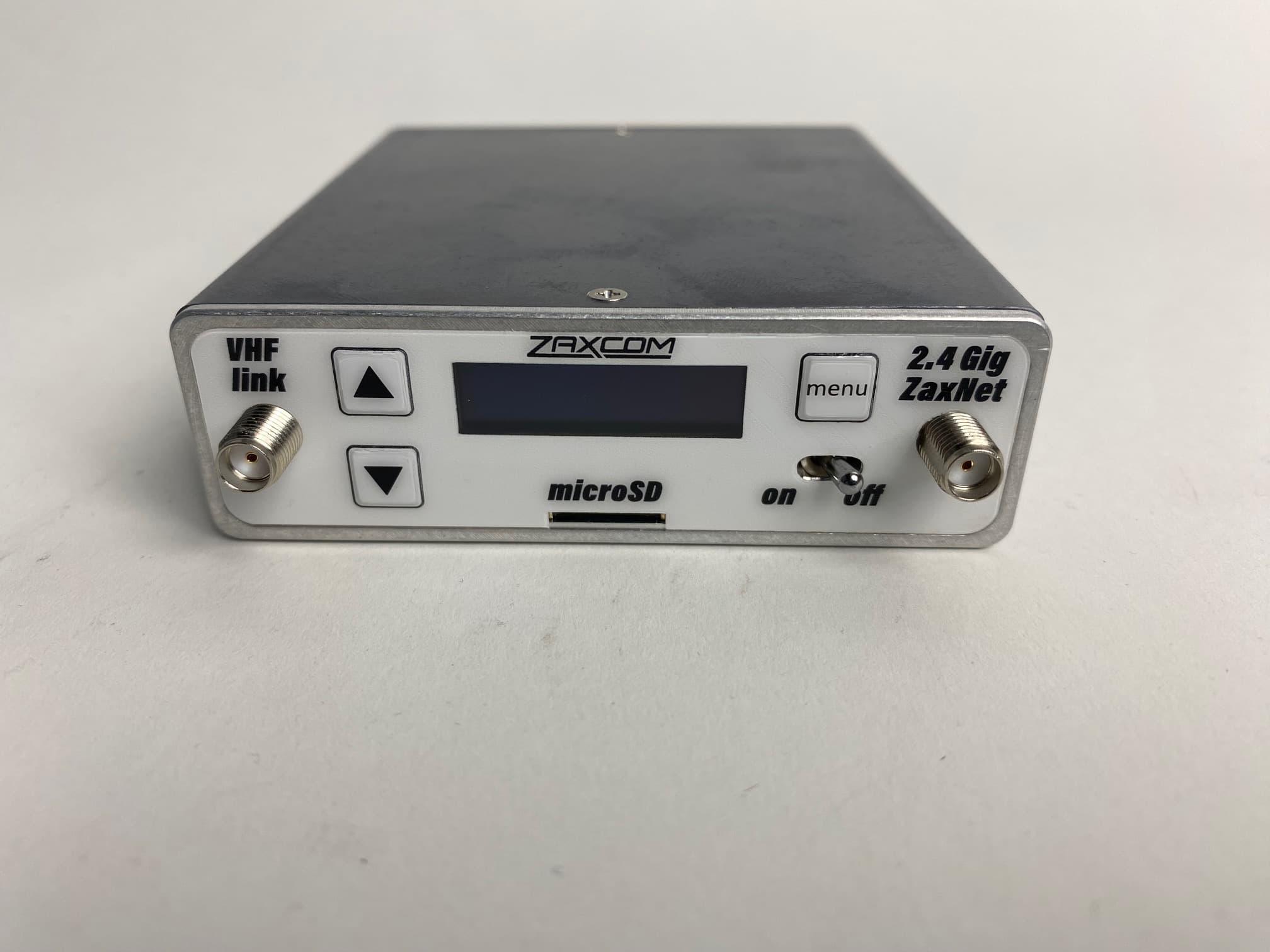
PR6VTX
Jan 16, 2025VHF IFB Transmitter
Equipment Class
TLD - Licensed LPAS Device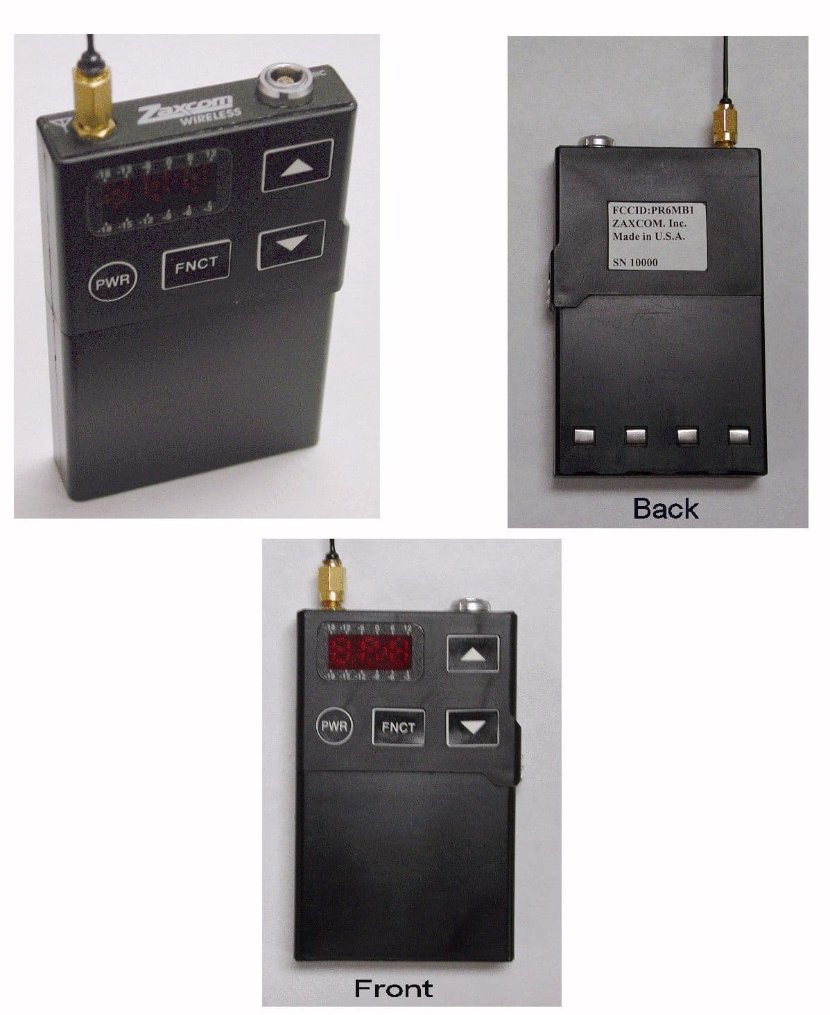
PR6MB1
Oct 29, 2001Digital Wireless Microphone
Equipment Class
TBT - Licensed Broadcast Transmitter Worn on Body