PRDKB73Gaming Keyboard
Acrox Technologies Co., Ltd.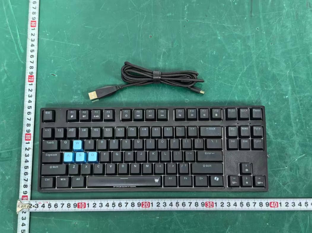
Click to zoom
Application Details
- Equipment Class
- DTS - Digital Transmission System
- Date of Grant
- Apr 03, 2026
- Application Purpose
- Original Equipment
- Equipment Note
- Gaming Keyboard
- Frequency Range
- 2402.00000000 - 2480.00000000
- Company
- Acrox Technologies Co., Ltd.
- Country
- Taiwan
Documents & Files
Document Text
Text extracted from the exhibit documents filed with the FCC. Open a document above to read the original.
Users Manual
Quick Start Guide / Guide de démarrage rapide Kurzanleitung / Guía de inicio rápido Guida rapida / Snabbstartsguide Hurtigstartguide / Guide til hurtig opstart Stručná referenční příručka / Skrócona instrukcja obsługi Hızlı Başlangıç Kılavuzu / Краткое руководство دليل البدء السريع / Guía de inicio rápido Guia de início rápido / Guide de démarrage rapide 快速入門指南 / 快速入门使用指南 PREDATOR AETHON 550 PKR400 1 English Quick Start Guide This guide outlines the operating procedures and safety precautions. Please read it carefully to make sure you are using your product properly and keep it for future reference. Specifications • Model: PKR400 • Connector Type: USB • Switch: Mechanical switch • Key No: 87 Keys • Backlight: RGB • Cable Length: 1800 mm • Dimensions (L x W x H): 362 x 138 x 38 mm • Weight: 1015 g ± 10 g Getting Started Wired Plug & Play: Simply connect the keyboard to an available USB port and the keyboard will automatically install all necessary drivers. Wireless • BT Pairing: Need to support Swift BLE Pairing Press and hold the BT button (F2) for 3 seconds to enter pairing mode. During pairing, the F2 button (BT indicator light) flashes purple. Once pairing is successful, the light stays on for 10 seconds, then returns to the original light effect. If pairing exceeds 10 minutes, the F2 flashing purple light turns off (the original light effect is restored after completing the action). During BT pairing, short press the F2 button The BT channel indicator light displays channels 1-3 in sequence. The BT channel indicator light flashes the selected channel for 5 seconds and then returns the original light effect (CAPS, SCRLK). BT reconnection status The F2 button (BT indicator light) flashes purple until reconnection is successful and the light stays on for 10 seconds and then returns to the original light effect. If reconnection speed is too fast, the F2 button (BT indicator light) directly displays a steady light for 10 seconds, then returns to the original light effect. 2 English • 2.4G Pairing Plug the dongle into the computer. The keyboard automatically pairs within a 2-meter range (no need to re-plug). If automatic pairing fails, press the 2.4G button (F3) to force pairing. During forced pairing, the 2.4G button flashes purple. After successful pairing, the purple light stays on for 10 seconds before turning off. In 2.4G mode, the 2.4G button displays a purple light, and the original light effect will be restored after 10 seconds (the original light effect always restores after completing the action). 1. You can download the QuarterMaster software from http://go.acer.com/predator-quartermaster 2. Backlight mode, color and Marco can be adjusted after installation completes. (Drag and select the single or multiple keys to configure the lighting effect for the keyboard.) 3. In regions where Dynamic Lighting is supported in Windows 11, you can control the Lighting modes through Windows 11 by selecting [Settings] > [Personalization] > [Dynamic Lighting]. 4. Please note that in scenarios where Dynamic Lighting is supported, if you want to control Lighting modes by using QuarterMaster software, please select [Settings] > [Personalization] > [Dynamic Lighting] and turn off [Use Dynamic Lighting on my devices] and [Compatible apps in the foreground always control lighting]. Note • Low battery voltage: When the battery voltage is lower than 3.3V, the blank button light flashes red; when charging, the blank button indicator light stays on red. When the battery is fully charged, the blank button indicator light stays on green for 20 seconds and then goes out; the battery voltage is lower than After 3.1V, the keyboard automatically shuts down and the keys are invalid; the blank key indicator lights up and flashes red, indicating that the current state requires charging. • 2 independent indicators represent the status of CAPS and SCRLK (locked to red light); WINLOCK (button light effect indication, locked to TEAL BLUE; if not locked, the original light effect will be used). 3 English • Switch description: When OFF, plug in the USB CABEL to charge; in 2.4G & BT mode, plug in the USB CABEL to switch to USB wired mode. Keyboard function HotkeyDescription FN + FN + Adjust backlight brightness. Four sections can be adjusted. FN + FN + Adjust the color flow speed, three levels can be adjusted. WIN Lock. FN + WSwap A/S/D/W with up/down/left/right direction keys. FN + F1 ~ F12Please refer to the instructions: FN + F1: Lighting on/off FN + F2: BT mode FN + F3: 2.4G mode FN + F4: www web FN + F5: non FN + F6: Pre Track FN + F7: Play/Pause FN + F8: Next Track FN + F9: Mute FN + F10: Volume + FN + F11: Volume - FN + F12: Calculator 4 English Hot-swapping for Mechanical Switches • Remove Keycap Use Keycap Puller to remove the Keycap. • Remove Switch Use Switch Puller to remove the switch. Warning: It is very easy to scratch your keyboard case with the tool, so take caution when removing switch. • Insert Switch Align switch to holes on the keyboard and insert straight down. There should be minimal resistance, and the switch should pop into the frame of the keyboard. • Insert Keycap Once you have confirmed the switch was properly inserted, snap back in the appropriate keycap. 5 English Package Contents • Predator Gaming Keyboard x 1 • Swappable mechanical red switch x 4 • Keycap-switch puller x 1 • USB Cable x 1 • Quick Start Guide x 1 • Warranty Booklet x 1 System Compatibility • Windows Operating System • Interface: USB port • Internet connection for optional software downloads Comfort Guideline Some research has suggested long periods of repetitive motion; using an improper operation space, body position, and poor work habits may be associated with physical discomfort and injury to nerves, tendons, and muscles. Below are some guidelines for optimizing comfort of usage and avoiding injury. 1. Put the keyboard and monitor in front of you, and place the mouse within easy reach. 2. Have your elbow next to you…
Text truncated - open the document above for the full version.
Attestation Statements
Acrox Technologies Co., Ltd. Covered Equipment Certification Attestation Letter 3/31/2026 Federal Communications Commission Authorization and Evaluation Division 7435 Oakland Mills Road Columbia, MD 21046 USA ATTN.: Reviewing Engineer FCC ID: PRDKB73 Acrox Technologies Co., Ltd. (“the applicant”) certifies that the equipment for which authorization is sought is not “covered” equipment prohibited from receiving an equipment authorization pursuant to section 2.903 of the FCC rules. Note: If the equipment for which the applicant seeks authorization is produced by any of the entities identified on the current Covered List, the applicant should include an explanation on why the equipment is not “covered” equipment. Acrox Technologies Co., Ltd. (“the applicant”) certifies that, as of the date of the filing of the application, the applicant is not identified on the Covered List (as a specifically named entity or any of its subsidiaries or affiliates) as an entity producing “covered” equipment. Acrox Technologies Co., Ltd. (“the applicant”) certifies that the equipment for which authorization is sought does not include cybersecurity or anti-virus software produced or provided by Kaspersky Lab, Inc. or any of its successors and assignees, including equipment with integrated Kaspersky Lab, Inc. (or any of its successors and assignees) cybersecurity or anti-virus software pursuant to DA-24-886 and KDB 986446 D01 Covered Equipment Guidance section B(2a). Signed: Printed name: Gavin Hsieh Title: Product Manager Company Name: Acrox Technologies Co., Ltd. Date: 3/31/2026
Attestation Statements
Acrox Technologies Co., Ltd. * the applicant must designate a contact located in the United States for purposes of acting as the applicant’s agent for service of process, regardless of whether the applicant is a domestic or foreign entity. An applicant located in the United States may designate itself as the agent for service of process. U.S. Agent Designation for Service of Process - Certification Attestation Letter 3/31/2026 Federal Communications Commission Authorization and Evaluation Division 7435 Oakland Mills Road Columbia, MD 21046 USA ATTN.: Reviewing Engineer FCC ID: PRDKB73 FRN of applicant: 0018333633 Per section 2.911(d)(7) of the FCC rules, Acrox Technologies Co., Ltd. (“the applicant”) certifies that the equipment for which authorization is sought is designated to the following U.S. agent* for service of process: Company Name: Acer America Corporation FCC Registration Number (FRN): 0033486168 Physical U.S. Company Address: 1730 N. 1st St. Suite 400 San Jose, CA 95112 United States Contact Person: young kim Agent Email Address: [email protected] The above contact person accepts the obligation for service of process. The applicant accepts to maintain an agent for no less than one year after the grantee has terminated all marketing and importation or the conclusion of any Commission-related proceeding involving the equipment. Applicant Signed: Agent Signed (if different from Applicant): Signed: Signed: Printed name: Gavin Hsieh Printed name: young kim Title: Product Manager Title: Director Company Name: Acrox Technologies Co., Ltd. Company Name: Acer America Corporation Date: 3/31/2026 Date: 3/31/2026
Cover Letter(s)
DATE : 3/31/2026 Federal Communications Commission Authorization & Evaluation Division 7345 Oakland Mills Road Columbia, Maryland 21046 Authority to Act as Agent On our behalf, I appoint EST Technology Co., Ltd. Address:Chilingxiang, Qishantou, Santun, Houjie, Dongguan, Guangdong, China to act as our agent in the preparation of this application for equipment certification. I certify that submitted documents properly describe the device or system for which equipment certification is sought. I also certify that each unit manufactured, imported or marketed, as defined in the Federal Communications Commission’s regulations will have affixed to it a label identical to that submitted for approval with this application. For instances where our authorized agent signs the application for certification on our behalf, I acknowledge that all responsibility for complying with the terms and conditions for certification, still resides with Acrox Technologies Co., Ltd. Address:4F., No.89, Minshan St., Neihu Dist., Taipei City 114, Taiwan <Signature> Name:Gavin Hsieh Title:Product Manager Applicant Company:Acrox Technologies Co., Ltd.
Cover Letter(s)
DATE : 3/31/2026 Federal Communications Commission Authorization & Evaluation Division 7345 Oakland Mills Road Columbia, Maryland 21046 RE: LETTER OF AGENT AUTHORIZATION To Whom It May Concern: We, the undersigned, hereby authorize Compliance Testing, LLC to act on our behalf in all matters relating to application for equipment authorization, including the signing of all documents relating to these matters. We also hereby certify that no party to the application authorized hereunder is subject to the denial of benefits, including FCC benefits, pursuant to Section 5301 of the Anti-Drug Abuse Act of 1988, 21 U.S.C.853(a). Sincerely, <Signature> Name:Gavin Hsieh Title:Product Manager Company:Acrox Technologies Co., Ltd.
Cover Letter(s)
DATE : 3/31/2026 Equipment Autorisation Division Federal Communications Commission 7435 Oakland Mills Road Columbia, MD 21046 FCC ID: PRDKB73 Product Name: Gaming Keyboard Request for Confidentiality Pursuant to Sections 0.457 and 0.459 of the commissions rules, we hereby request that the following documents be held confidential: Schematics Block diagram Operation description These materials contain trade secrets and proprietary information and are not customarily released to the public. The public disclosure of this information might be harmful to the company and provide unjustified benefits to our competitors. <Signature> Name:Gavin Hsieh Title:Product Manager Company:Acrox Technologies Co., Ltd.
Cover Letter(s)
Acrox Technologies Co., Ltd. I, the undersigned, Gavin Hsieh: The following models have the same technical construction including circuit diagram, PCB Layout, components and component layout, all electrical construction and mechanical construction, except the different model number. 1) Model No.: KM8 2) Model No.: PKR400 FCC ID: PRDKB73 Sincerely, Client’s signature : Client’s name / title : Gavin Hsieh / Product Manager Contact information / address : 4F., No.89, Minshan St., Neihu Dist., Taipei City 114, Taiwan Telephone: 886-2-2796-5888 Fax No.: 886-2-2793-8999
External Photos
External Photos M/N: KM8 External Photos M/N: KM8 External Photos M/N: KM8 External Photos M/N: KM8
ID Label/Location Info
Predator Aethon 550 Gaming Keyboard (電競键盘/电竞键盘) Model No. (Modelo/型號/型号): PKR400 Rated. (規格/规格): 5V 1000mA FCC ID: PRDKB73 TEL: 02-2696-0099 地址: 新北市汐止區新台五路一段88號8樓 Acer Inc.: 8F, 88, Sec 1, Xintai 5th Rd., Xizhi, New Taipei City, 221 使用方法:請參考使用手冊 緊急處理方法:宏碁客戶服務專線 0800-258-222 警告及注意事項:請參考使用手冊之警語與注意事項 Manufacturing Date/ Tarikh Pengilangan/Fecha de fabricación/ 生產日期/生产日期: Apr. 2026 Made in China/Buatan China/Hecho en China/中國製造/中国制造 EU: Viale delle Industrie, 1/A, 20044 Arese (MI), Italy S/N: GPKBD11058618000010Z01 69.5 mm 39.5 mm
Internal Photos
Internal Photos M/N: KM8 Internal Photos M/N: KM8 Internal Photos M/N: KM8 Internal Photos M/N: KM8 Internal Photos M/N: KM8 Internal Photos M/N: KM8 PCB Antenna
RF Exposure Info
Page 1 of 3 Report No. ESTE-R2603097 FCC RF EXPOSURE REPORT Acrox Technologies Co., Ltd. Gaming Keyboard Model Number: KM8 Additional Model: PKR400 FCC ID: PRDKB73 Applicant: Acrox Technologies Co., Ltd. Address: 4F., No.89, Minshan St., Neihu Dist., Taipei City 114, Taiwan Prepared By: EST Technology Co., Ltd. Chilingxiang, Qishantou, Santun, Houjie, Dongguan, Guangdong, China Tel: 86-769-83081888-808 Report Number: ESTE-R2603097 Date of Test: Nov. 21, 2025 to Mar. 04, 2026 Date of Report: Mar. 18, 2026 Page 2 of 3 Report No. ESTE-R2603097 1. Applicable Standards FCC Part 2(Section 2.1093) FCC KDB 447498 D04 Interim General RF Exposure Guidance v01 2. Exposure Evaluation of Portable or Mobile Devices Human exposure to RF emissions from portable devices (47 CFR §2.1093), as defined by the FCC, must be evaluated with respect to the FCC-adopted limits for SAR. Evaluation of mobile devices, as defined by the FCC, may also be performed with respect to SAR limits, but in such cases it is usually simpler and more cost-effective to evaluate compliance with respect to field strength or power density limits. For certain devices that are designed to be used in both mobile and portable configurations similar to those described in 47 CFR §2.1091(d)(4), such as certain desktop phones and wireless modem modules, compliance for mobile configurations is also satisfied when the same device is evaluated for SAR compliance in portable configurations. The test exclusions are applicable only when the minimum test separation distance is ≤ 50 mm and for transmission frequencies between 300 MHz and 6 GHz. When the minimum test separation distance is < 5 mm, a distance of 5 mm is applied to determine SAR test exclusion. Page 3 of 3 Report No. ESTE-R2603097 3. Evaluation Results Mode CH Peak Output Power (dBm) Antenna Gain (dBi) Effective Radiated Power (dBm) Target Power (dBm) Max. Target Power (mW) SAR Test Exemption Limit (mW) BLE 2M 2402 -2.75 0 -4.90 -4±1 0.501 2.72 2440 -2.00 0 -4.15 -4±1 0.501 2.72 2480 -1.90 0 -4.05 -4±1 0.501 2.72 For 2.4G SRD Field strength = 76.42dBuV/m@3m P={ [10 (76.42/20) /10 6 *3] 2 /30 }*1000mW =0.013mW< 2.72mW Note: 1. Limited=3060*(0.5/20)^x, x=-log(60/(3060*√f)). 2. We choose f=2.48GHz (Highest frequency operate at bluetooth) to calculate MPE limit as higher frequency will have lower MPE limits. 3. SAR Test Exclusion Thresholds is 2.72mW for separation distance 5mm. Therefore, SAR test is not required. End of Test Report
Test Report
Dongguan JUTONG Electronics Co.,Ltd Sepcification For Approval Provider: Dongguan JUTONG Electronics Co.,Ltd Model No.: DA36 Part name: Integral Antenna Approval: Date: 2018-9-27 Structure Drawing RF Antenna Assembly Test/Position Gain/Free Space Frequency(MHz) 2400 2450 2500 Ant. Port Input Pwr.(dBm) 0.00 0.00 0.00 Tot.Rad.Pwr.(dBm) -2.95 -3.00 -3.11 Peak EIRP(dBm) 0.00 -0.55 -0.68 Directivity(dBi) 2.46 2.46 2.44 Efficiency(dB) -2.95 -3.00 -3.11 Effciency(%) 50.72 50.08 48.81 Gain(dBi) 0.00 -0.55 -0.68 2400MHz 2450MHz 2500MHz
Test Report
Page 1 of 18 Report No.ESTE-R2603095 Appendix A: DTS Bandwidth Test Result TestMode Antenna Frequency[MHz] DTS BW [MHz] FL[MHz] FH[MHz] Limit[MHz] Verdict BLE_2M Ant1 2402 1.116 2401.364 2402.480 0.5 PASS BLE_2M Ant1 2440 1.128 2439.346 2440.474 0.5 PASS BLE_2M Ant1 2480 1.110 2479.382 2480.492 0.5 PASS Page 2 of 18 Report No.ESTE-R2603095 Test Graphs BLE_2M-Ant1-2402-PASS BLE_2M-Ant1-2440-PASS BLE_2M-Ant1-2480-PASS Page 3 of 18 Report No.ESTE-R2603095 Page 4 of 18 Report No.ESTE-R2603095 Appendix B: Maximum conducted output power Test Result Peak TestMode Antenna Frequency[MHz] Conducted Peak Power[dBm] Conducted Limit[dBm] Verdict BLE_2M Ant1 2402 -2.75 ≤30 PASS BLE_2M Ant1 2440 -2.00 ≤30 PASS BLE_2M Ant1 2480 -1.90 ≤30 PASS Test Graphs Peak BLE_2M-Ant1-2402-PASS BLE_2M-Ant1-2440-PASS Page 5 of 18 Report No.ESTE-R2603095 BLE_2M-Ant1-2480-PASS Page 6 of 18 Report No.ESTE-R2603095 Appendix C: Maximum power spectral density Test Result TestMode Antenna Frequency[MHz] Result[dBm/3kHz] Limit[dBm/3kHz] Verdict BLE_2M Ant1 2402 -19.86 ≤8.00 PASS BLE_2M Ant1 2440 -19.22 ≤8.00 PASS BLE_2M Ant1 2480 -19.01 ≤8.00 PASS Page 7 of 18 Report No.ESTE-R2603095 Test Graphs BLE_2M-Ant1-2402-PASS BLE_2M-Ant1-2440-PASS BLE_2M-Ant1-2480-PASS Page 8 of 18 Report No.ESTE-R2603095 Page 9 of 18 Report No.ESTE-R2603095 Appendix D: Reference level measurement Test Result TestMode Antenna Freq(MHz) Max.Point[MHz] Result[dBm] BLE_2M Ant1 2402 2401.88 -5.83 BLE_2M Ant1 2440 2439.93 -3.02 BLE_2M Ant1 2480 2479.93 -2.95 Page 10 of 18 Report No.ESTE-R2603095 Test Graphs BLE_2M-Ant1-2402-PASS BLE_2M-Ant1-2440-PASS BLE_2M-Ant1-2480-PASS Page 11 of 18 Report No.ESTE-R2603095 Page 12 of 18 Report No.ESTE-R2603095 Appendix E: Band edge measurements Test Result TestMode Antenna ChName Frequency [MHz] RefLevel[dBm] Result[dBm] Limit[dBm] Verdict BLE_2M Ant1 Low 2402 -5.83 -33.05 ≤-25.83 PASS BLE_2M Ant1 High 2480 -2.95 -39.42 ≤-22.95 PASS Page 13 of 18 Report No.ESTE-R2603095 Test Graphs BLE_2M-Ant1-2402-PASS BLE_2M-Ant1-2480-PASS Page 14 of 18 Report No.ESTE-R2603095 Appendix F: Conducted Spurious Emission Test Result TestMode Antenna Frequency[MHz] FreqRange [MHz] RefLevel [dBm] Result[dBm] Limit[dBm] Verdict BLE_2M Ant1 2402 30~26500 -5.83 -41.93 ≤-25.83 PASS BLE_2M Ant1 2440 30~26500 -3.02 -41.92 ≤-23.02 PASS BLE_2M Ant1 2480 30~26500 -2.95 -41.53 ≤-22.95 PASS Page 15 of 18 Report No.ESTE-R2603095 Test Graphs BLE_2M-Ant1-2402-30~26500-PASS BLE_2M-Ant1-2440-30~26500-PASS BLE_2M-Ant1-2480-30~26500-PASS Page 16 of 18 Report No.ESTE-R2603095 Page 17 of 18 Report No.ESTE-R2603095 Appendix G: Duty Cycle Test Result TestMode Antenna Frequency[MHz] ON Time [ms] Period [ms] Duty Cycle [%] Duty Cycle Factor[dB] BLE_2M Ant1 2440 0.20 2.49 8.03 10.95 Page 18 of 18 Report No.ESTE-R2603095 Test Graphs NTNV-BLE_2M-Ant1-2440
Test Report
Page 1 of 50 Report No.ESTE-R2603095 FCC PART 15C TEST REPORT FOR CERTIFICATION On Behalf of Acrox Technologies Co., Ltd. Gaming Keyboard Model Number: KM8 Additional Model: PKR400 FCC ID: PRDKB73 Applicant: Acrox Technologies Co., Ltd. Address: 4F., No.89, Minshan St., Neihu Dist., Taipei City 114, Taiwan Prepared By: EST Technology Co., Ltd. Chilingxiang, Qishantou, Santun, Houjie, Dongguan, Guangdong, China Tel: 86-769-83081888-808 Report Number: ESTE-R2603095 Date of Test: Nov. 21, 2025 to Mar. 04, 2026 Date of Report: Mar. 18, 2026 Page 2 of 50 Report No.ESTE-R2603095 TABLE OF CONTENTS Description Page TEST REPORT VERIFICATION .......................................................................................................... 3 1. GENERAL INFORMATION ................................................................................................................... 5 1.1. Description of Device (EUT) ............................................................................................................ 5 1.2. Antenna Information ......................................................................................................................... 5 1.3. Information of RF Cable ................................................................................................................... 5 2. SUMMARY OF TEST ........................................................................................................................... 6 2.1. Summary of test result ..................................................................................................................... 6 2.2. Test Facilities ..................................................................................................................................... 7 2.3. Measurement uncertainty ................................................................................................................ 8 2.4. Assistant equipment used for test .................................................................................................. 8 2.5. Block Diagram ................................................................................................................................... 8 2.6. Test Mode .......................................................................................................................................... 9 2.7. Power Setting of Test Software ...................................................................................................... 9 2.8. Duty Cycle .......................................................................................................................................... 9 2.9. Channel List ..................................................................................................................................... 10 2.10. Test Equipment List ...................................................................................................................... 11 3. 6DB BANDWIDTH ............................................................................................................................ 13 3.1. Limit ................................................................................................................................................... 13 3.2. Test Setup ........................................................................................................................................ 13 3.3. Spectrum Analyzer Setting ............................................................................................................ 13 3.4. Test Procedure ................................................................................................................................ 13 3.5. Test Result ....................................................................................................................................... 13 4. MAXIMUM PEAK OUTPUT POWER .................................................................................................. 14 4.1. Limit ................................................................................................................................................... 14 4.2. Test Setup ........................................................................................................................................ 14 4.3. Spectrum Analyzer Setting ............................................................................................................ 14 4.4. Test Procedure ................................................................................................................................ 14 4.5. Test Result ....................................................................................................................................... 14 5. POWER SPECTRAL DENSITY .......................................................................................................... 15 5.1. Limit ................................................................................................................................................... 15 5.2. Test Setup ........................................................................................................................................ 15 5.3. Spectrum Analyzer Setting ............................................................................................................ 15 5.4. Test Procedure ................................................................................................................................ 15 5.5. Test Result ....................................................................................................................................... 15 6. CONDUCTED BAND EDGE .............................................................................................................. 16 6.1. Limit ................................................................................................................................................... 16 6.2. Tes…
Text truncated - open the document above for the full version.
Test Setup Photos
Conducted Emissions Test Radiated Test (30-1000 MHz) Radiated Test (Above 1GHz)
Contact Information
Applicant
Gavin Hsieh(Product Manager)
[email protected]Fax: 886-2-2793-8999
Technical Contact
Acer America Corporationyoung kim
1730 N. 1st St. Suite 400 · San Jose, California, 95112 · United States
Test Firm
EST Technology Co., Ltd.Iceman Hu
Technical Specifications
| # | Rule Parts | Frequency Range | Power Output |
|---|---|---|---|
| 1 | 15C | 2.40 GHz - 2.48 GHz | 645.70 µW |
Other Applications from Acrox Technologies Co., Ltd.
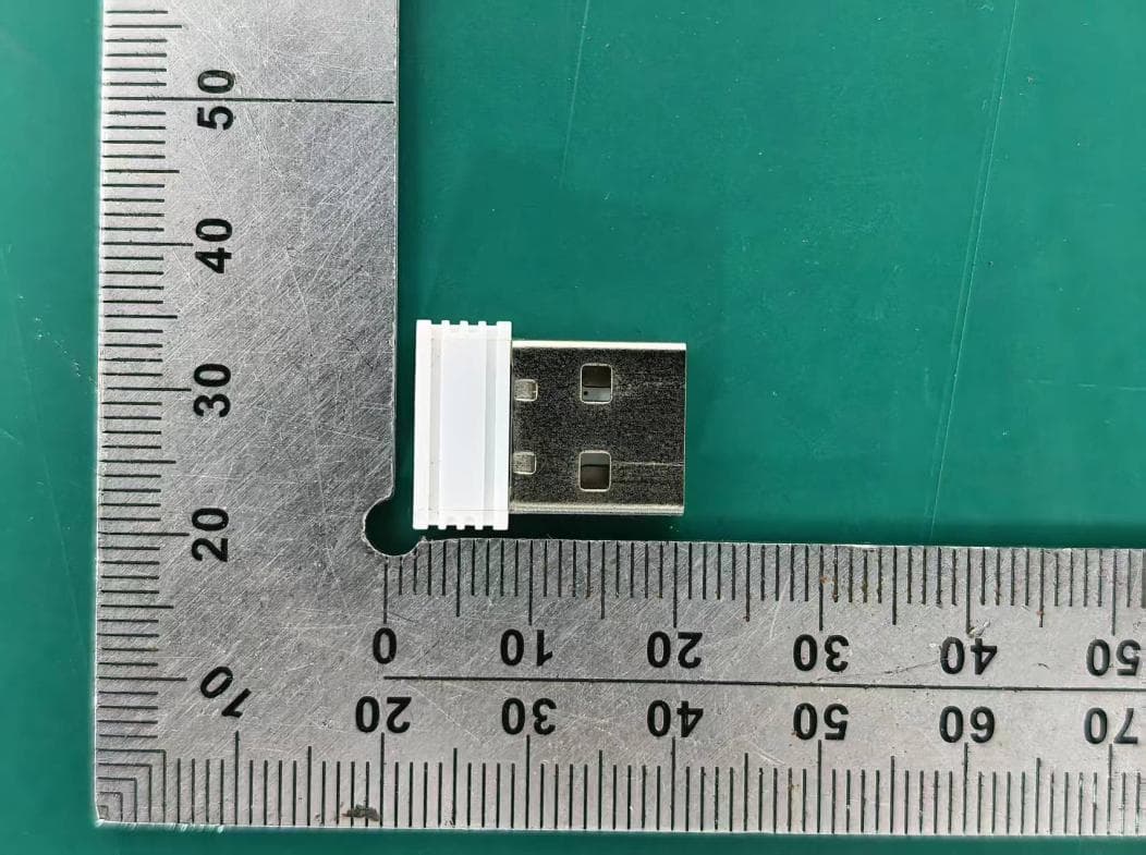
PRDRX12
May 27, 2026Wireless Receiver
Equipment Class
DXX - Part 15 Low Power Communication Device Transmitter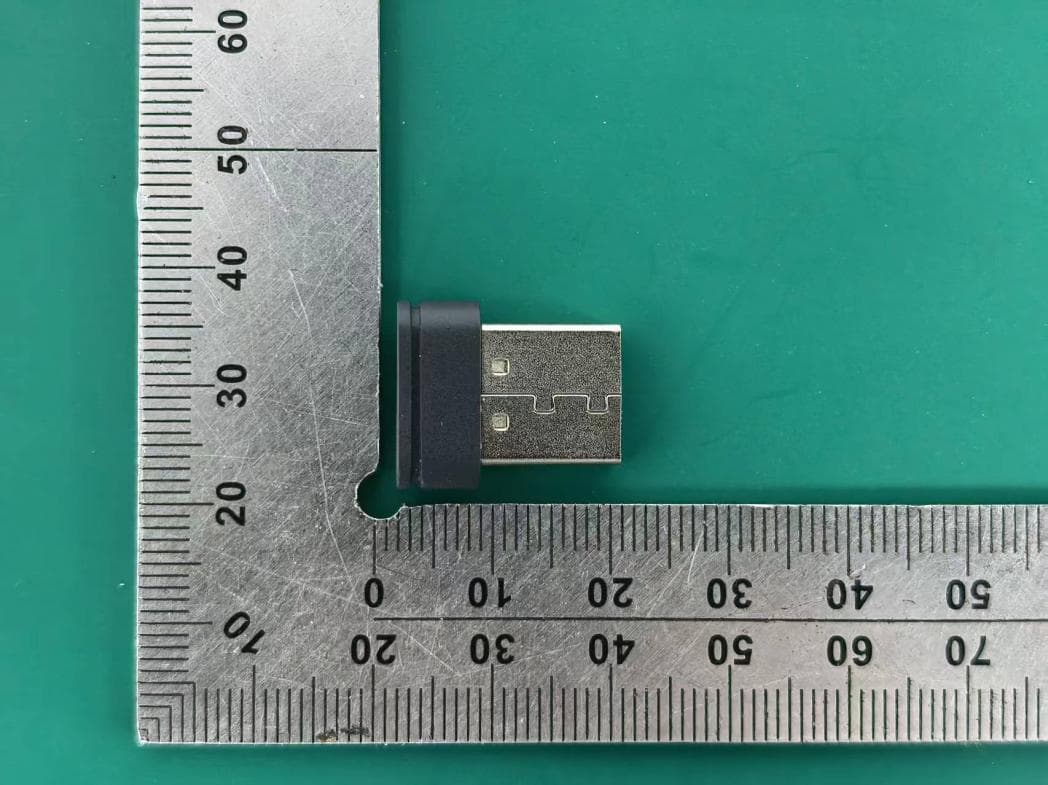
PRDRX11
Apr 07, 2026Wireless Receiver
Equipment Class
DXX - Part 15 Low Power Communication Device Transmitter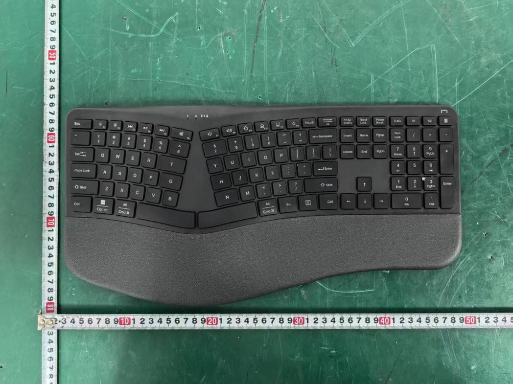
PRDKB72
Apr 03, 2026WIRELESS SPLIT KEY ERGONOMIC KEYBOARD
Equipment Class
DTS - Digital Transmission System
PRDRX1P
Apr 03, 2026Wireless Receiver
Equipment Class
DXX - Part 15 Low Power Communication Device Transmitter
PRDMU146
Mar 27, 2026DUAL MODE CONTOUR MOUSE STONE
Equipment Class
DTS - Digital Transmission System