PRQ-FD-3100ADistributed Antenna System
Avitec, AB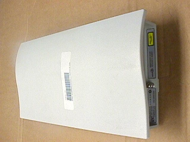
Click to zoom
Application Details
- Equipment Class
- AMP - Amplifier
- Date of Grant
- Apr 17, 2002
- Application Purpose
- Original Equipment
- Date of Application
- Apr 17, 2002
- Equipment Note
- Distributed Antenna System
- Frequency Range
- 1930.00000000 - 1990.00000000
- Company
- Avitec, AB
- Country
- Sweden
Documents & Files
Document Text
Text extracted from the exhibit documents filed with the FCC. Open a document above to read the original.
Users Manual
Operating Manual FiberDAS Distributed Antenna System FiberDAS Manual, Rev. E14 ii Table of Contents 1 LINK DESCRIPTION..................................................................................................................................1-1 1.1 C AUTIONS AND W ARNINGS ......................................................................................................................1-1 1.2 G ENERAL D ESCRIPTION ............................................................................................................................1-2 1.2.1 Basic Principles...............................................................................................................................1-2 1.2.2 Functional Description....................................................................................................................1-3 1.3 S PECIFICATIONS .......................................................................................................................................1-7 2 INSTALLATION...........................................................................................................................................2-1 2.1 G ENERAL P ROCEDURE ..............................................................................................................................2-1 2.2 I NSTALL F IBEROPTIC C ABLES ...................................................................................................................2-5 2.2.1 Minimizing Optical Reflections.......................................................................................................2-5 2.2.2 Cleaning Optical Connectors..........................................................................................................2-6 2.3 S YSTEM A LARMS ......................................................................................................................................2-7 2.4 H UB S HELF AND R EMOTE P OWER S UPPLY B ATTERY C HARGE M ONITORING AND R EPLACEMENT ...........2-7 2.4.1 Replacing the Hub Shelf Battery......................................................................................................2-8 2.4.2 Replacing the Remote Power Supply Battery..................................................................................2-8 2.5 I NSTALLATION C HECKLIST .......................................................................................................................2-9 2.5.1 Inspect Received Items.....................................................................................................................2-9 2.5.2 Recommended Tools........................................................................................................................2-9 2.6 I NSTALLING THE H UB S HELF ....................................................................................................................2-9 2.6.1 Rack Installation..............................................................................................................................2-9 2.6.2 Connect Fiberoptic Cables............................................................................................................2-10 2.6.3 Indentifying Remote Locations......................................................................................................2-10 2.6.4 Serial Bus, Telephone and Local Alarm Connections...................................................................2-10 2.6.5 Mains Power and Fuses.................................................................................................................2-10 2.6.6 RF Connections.............................................................................................................................2-11 2.7 I NSTALLING THE R EMOTE T RANSCEIVERS ..............................................................................................2-11 3 MONITORING AND TROUBLESHOOTING..........................................................................................3-1 3.1 F IELD S UPPORT N UMBERS ........................................................................................................................3-1 3.2 T ROUBLESHOOTING T IPS ..........................................................................................................................3-2 3.3 R EGULATORY ...........................................................................................................................................3-4 iii iv 1 Link Description 1.1 Cautions and Warnings Throughout this manual, these terms appear which highlight the care that should be exercised to ensure personal safety and proper operation of the equipment. WARNING: Warning statements identify conditions or practices that could result in injury or loss of life. CAUTION: Caution statements identify conditions or practices that could result in damage to this product or other property. CAUTION: any modifications to this device not expressly authorized by Remec, Inc. could void the user’s authority to operate this device. CLASS 1 LASER PRODUCT FDA/CDRH Class 1 laser product. All versions of the FiberDAS are Class 1 lasers products per CDRH, 21 CFR 1040 Laser Safety requirements. All versions are Class 1 laser products per EN 60825-1:1994. NOTICE UNTERMINATED OPTICAL RECEPTACLES MAY EMIT LASER RADIATION. DO NOT VIEW WITH OPTICAL INSTRUMENTS. 1-1 1.2 General Description The FiberDAS Fiberoptic Distributed Antenna System provides extended coverage of wireless networks throughout buildings and campus environments. The Hub Shelf is a 3U (5.25 inch) high, 19-inch wide rack-mounted chassis. The Hub Shelf holds up to 8 Hub Transceiver Plug-Ins. The Hub Shelf is located in a communications equipment room in the building and is connected to the wireless base station or repeater via hardline connection. The Hub Shelf may also be connected to the radios of a wireless PBX. Each Hub Shelf is configured with up to eight Hub Transceiver plug-in …
Text truncated - open the document above for the full version.
Operational Description
1.2 General Description The FiberDAS Fiberoptic Distributed Antenna System provides extended coverage of wireless networks throughout buildings and campus environments. The Hub Shelf is a 3U (5.25 inch) high, 19-inch wide rack-mounted chassis. The Hub Shelf holds up to 8 Hub Transceiver Plug-Ins. The Hub Shelf is located in a communications equipment room in the building and is connected to the wireless base station or repeater via hardline connection. The Hub Shelf may also be connected to the radios of a wireless PBX. Each Hub Shelf is configured with up to eight Hub Transceiver plug-in cards. Each card is connected to up to two Remote Transceivers via two pairs of singlemode fiberoptic lines. The Remote Transceiver Units are distributed throughout the building as necessary to provide coverage. The Remote Transceivers are mounted, generally, above the suspended ceiling but may be mounted near the ceiling inside the room if need be. The aesthetic and low-profile design of the Remote Transceiver makes it relatively unobtrusive. The plastic cover may even be removed and/or painted to match the décor. Each Remote Transceiver is connected to Hub Shelf via two singlemode optical fibers. Each Remote Transceiver has one RF port which is connected to a user-supplied indoor coverage antenna. This port may also be routed through an N- way RF splitter to provide coverage from a number N antennas for the one Remote Transceiver. The choice depends on the results of the engineering design for that particular structure as to the most cost- effective way to provide uniform coverage. The Remote Transceiver is DC-powered, usually by the Remec Central DC Power Supply. This is distributed from the power supply at the Hub location using the conductor pairs in a composite fiber/conductor cable or by a separate two-wire cable pulled along with the fiberoptic cable. The DC connector utilized at the Remote Transceiver can accommodate up to 14 AWG wire. The FiberDAS design is very versatile but certain options are available that target specific signal types and applications. In addition to the single band versions from iDEN through UMTS, there are dual band versions such as 800 MHz/1900 MHz and GSM900/GSM1800. FiberDAS installation and setup is very simple. First, standard telcom grade singlemode fiberoptic cable that is most suitable for the site is installed. The cable installer can terminate the cable on site easily with the SC/UPC optical connectors. The Plug-Ins and Remote Transceivers of a given type are completely interchangeable. The SC/UPC plugs directly into the Remote Transceiver at one end. The other end plugs into an optical patch panel or directly into the Hub Shelf via an SC/UPC-to-SC/UPC adapter. If the patch panel is used, SC/UPC-to-SC/UPC jumpers must be used to connect the Hub Shelf to the patch panel. Built-in optical loss compensation automatically equalizes the gain in both the transmit and receive paths so the transmit RF power is known for a given input RF power and the receive path sensitivity is optimized. The only adjustment available is a manual setting for the static transmit power at the Remote Transceiver which may be used to optimize coverage, if necessary. This is a one time adjustment during set up. 1.2.1 Basic Principles The FiberDAS operation is based on an analog RF fiberoptic link. The principles are illustrated in Figure 1. Input RF signals are converted to light by direct intensity modulation of a semiconductor laser. This modulated light is transmitted over optical fiber and detected by a semiconductor PIN photodiode. The photodiode converts optical power to electrical current. This current is AC coupled and passed through a load to recover the RF signal. The basic RF loss in this link is determined by the inefficiencies of the conversions of RF to optical and back. The fiber also contributes an RF loss equal to twice the optical loss. This is because the photodiode converts optical power to electrical current and RF power is proportional to the square of the current. So, for 1 km of fiber with a loss of 0.4 dB/km (this is typical at 1310 nm wavelength) the optical loss is 0.4 dB 1-2
Parts List/Tune Up Info
May 6, 2002 Attn: Review Engineer Federal Communications Commission 7435 Oakland Mills Road Columbia, MD 21046 Subject: Tune-up procedure To w hom it May Concern: Per your requested, you can find the tune up procedure is on the operating manual under section 1.2 General Description: .... The only adjustment available is a manual setting for the static transmit power at the Remote Transceiver which may be used to optimize coverage, if necessary. This is a one-time adjustment during set up. Please fell free to contact us w ith any questions you may have about this letter. Sincerely, Gary Grimes Managing Director Phone: (714)765-5813 Fax(714)765-5817
Contact Information
Applicant
Hakan Samuelsson(Managing Director)
46 8-475-4700Fax: 46 8-475-4799
Test Firm
MET Laboratories, Inc.John Mason
Technical Specifications
| # | Rule Parts | Frequency Range | Power Output | Emission |
|---|---|---|---|---|
| 2 | 24 | 1.93 GHz - 1.99 GHz | 110.00 mW | F9W |
Other Applications from Avitec, AB
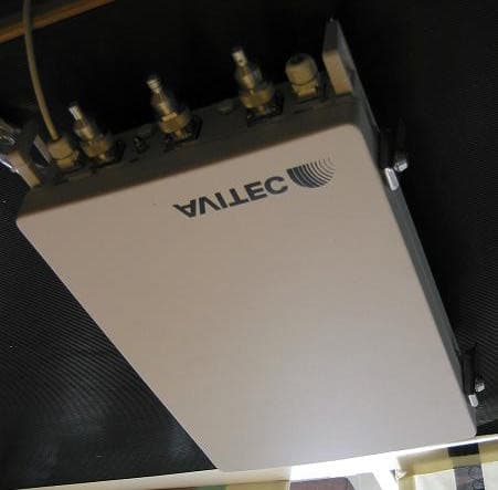
PRQCSFT1922
Oct 19, 2004Extender GSM/EDGE
Equipment Class
PCB - PCS Licensed Transmitter
PRQ-FD-3500A
Apr 17, 2002Distributed Antenna System
Equipment Class
AMP - Amplifier