PRQCSFT1922Extender GSM/EDGE
Avitec, AB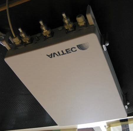
Click to zoom
Application Details
- Equipment Class
- PCB - PCS Licensed Transmitter
- Date of Grant
- Oct 19, 2004
- Application Purpose
- Original Equipment
- Date of Application
- Oct 19, 2004
- Equipment Note
- Extender GSM/EDGE
- Frequency Range
- 1930.20000000 - 1989.20000000
- Company
- Avitec, AB
- Country
- Sweden
Documents & Files
Document Text
Text extracted from the exhibit documents filed with the FCC. Open a document above to read the original.
Users Manual
Product Description and User’s Manual GSM-EDGE REPEATERS GSM-EDGE Repeaters PRODUCT DESCRIPTION AND USER’S MANUAL © Avitec AB A1009300 A 1 (177) GSM-EDGE 900, 1800 and 1900 Repeaters Product Description and User’s Manual This document is valid for Firmware version 1.03 and RMC version 2.12 This document is valid for the repeater models: • CSR 922, CSR924, CSR 924H • CSR 1822, CSR 1824 • CSR 1922, CSR 1924 • CSFT 922, CSFT 91822 • CSFT 1822, CSFT 18922 • CSFT 1922 • CSF 922 Copyright © 2004 AVITEC AB All rights reserved. No part of this document may be copied, distributed, transmitted, transcribed, stored in a retrieval system, or translated into any human or computer language without the prior written permission of Avitec AB. The manufacturer has made every effort to ensure that the instructions contained in this document are adequate and free of errors and omissions. The manufacturer will, if necessary, explain issues which may not be covered by this document. The manufacturer's liability for any errors in the document is limited to the correction of errors and the aforementioned advisory services. This document has been prepared to be used by professional and properly trained personnel, and the customer assumes full responsibility when using them. The manufacturer welcomes customer comments as part of the process of continual development and improvement of the documentation in the best way possible from the user's viewpoint. Please submit your comments to the nearest Avitec AB sales representative. GSM-EDGE Repeaters PRODUCT DESCRIPTION AND USER'S MANUAL © Avitec AB A1009300 A 2 (177) Table of Contents 1 Repeater Technology ................................................................................................................ 13 1.1 Basic Features.................................................................................................................... 13 1.2 Repeater Types ..................................................................................................................13 1.3 Repeater Applications ....................................................................................................... 17 1.4 Software Overview ............................................................................................................ 20 2 Product Description .................................................................................................................. 21 2.1 Repeater Models................................................................................................................21 2.2 Characteristics ................................................................................................................... 22 2.3 Casing................................................................................................................................ 28 2.4 Connections ....................................................................................................................... 30 2.5 Power and Back-up Battery ............................................................................................... 34 2.6 Building Blocks .................................................................................................................34 2.7 Internal Connections.......................................................................................................... 40 2.8 Signal Paths ....................................................................................................................... 42 3 Monitoring and Control ........................................................................................................... 46 3.1 Software Features ..............................................................................................................46 3.2 RF Parameters ...................................................................................................................50 3.3 Hardware Identification ..................................................................................................... 54 3.4 Alarm System ....................................................................................................................55 3.5 Repeater Heartbeat ............................................................................................................ 65 3.6 Traffic Measurement ......................................................................................................... 66 3.7 Remote Communication .................................................................................................... 70 3.8 Upgrading Repeater Firmware .......................................................................................... 84 4 Installation ................................................................................................................................. 85 4.1 Prepare the Site.................................................................................................................. 86 4.2 Install the Repeater .......................................................................................................... 104 4.3 Start-up the Repeater ....................................................................................................... 115 4.4 Configure the Repeater.................................................................................................... 120 4.5 Installation Checklists ..................................................................................................... 136 5 Maintenance ............................................................................................................................ 141 5.1 General ............................................................................................................................ 141 5.2 Preventive Maintenance .................................................................................................. 141 6 Specifications .....…
Text truncated - open the document above for the full version.
Users Manual
GSM-EDGE Repeaters PRODUCT DESCRIPTION AND USER'S MANUAL © Avitec AB A1009300 A 104 (177) 4.2 Install the Repeater Instructions in the left column are fast track instructions and can be used by experienced users. Other users are recommended to read the complete text in this installation guide 4.2.1 Unpack the Repeater Unpack the repeater Inspect the shipped material before unpacking the equipment, document any visual damage and report according to routines. A delivery of a repeater from Avitec contains: ! Checklist with delivered items ! Repeater ! Wall mounting kit or rack mounting kit (defined in order) ! 4 bolts for attaching repeater to mounting kit ! Cable cover ! Keys to repeater and cable cover ! CD containing Product Description and User’s Manual ! Any other specifically ordered item 4.2.2 Mount the Repeater Mount the repeater on a wall, on a pole or in a rack Mount the repeater in an accessible location and in a location that fulfils the environmental requirements. The repeater can be mounted on the wall, on a pole or in a 19 inch rack. The Repeater is delivered with a wall mounting kit or a rack mounting kit. The repeater needs to be mounted tightly to eliminate vibrations Wall mounting kit Rack mounting kit Ensure proper ventilation Mount the repeater so that heat can be dispersed from it. The repeater wall mounting kit ensures an optimum airflow between the wall and the repeater itself. Do not block this air channel as it will cause the MTBF of the repeater to drop dramatically, or even in the worst case cause the repeater to fail completely. If possible use a wall in the shadow to minimize the overall sun loading. If sufficient shielding cannot be obtained, an additional sun shield should be mounted. GSM-EDGE Repeaters PRODUCT DESCRIPTION AND USER'S MANUAL © Avitec AB A1009300 A 105 (177) Example of a sun shield 4.2.3 Ensure Proper Grounding Connect the grounding protection Ensure that good grounding protection measures are taken to create a reliable repeater site. Make sure to use adequately dimensioned grounding cables. The minimum recommended conductive area for a grounding cable is 16mm 2. The antenna cabling should be connected to ground every 10m by a reliable grounding kit. Make sure the grounding product used is suitable for the kind and size of cable being used. Connect the repeater box bolt to the same ground. Ground Ground connector on repeater GSM-EDGE Repeaters PRODUCT DESCRIPTION AND USER'S MANUAL © Avitec AB A1009300 A 106 (177) 4.2.4 Ensure Good EMV Protection (Lightning) Caution If insufficient Electro magnetic Protection is provided, or if EMV measures are not taken, warranties issued by Avitec are not valid. Connect the lightning protection The lightning hazard to electric and electronic equipment consists in the interferences of direct lightning current infections and high surge voltages induced by the electromagnetic field of nearby lightning channels or down conductors. Amplitudes from cloud-to-earth lightning amounts to several 10kA and may last longer than 2 ms. The damage caused depends on the energy involved and on the sensitivity of the electronics systems. Ensure that lightning protection measures are taken to create a reliable repeater site. Protect all coaxial cables and power cables from the transients caused by lightning. Fit all cables with suitable lightning protection devices. For detailed information please refer to IEC 61024-1 and 61312-1 for international standards for protection of information systems against LEMP, Lightning Electromagnetic Pulse, including radio transmitters. They define proper planning, installation and inspection of effective lightning protection systems. Antennas Repeater Primary Protective Devices Equipotential Grounding Bars 230V AC/48V DC Protective Device Secondary Protective Devices The top of the mast must be higher than the antennas and be properly grounded The grounding path must have reliable continuity and be correctly dimensioned The Avitec repeaters comply with the EN standard ETS 301 498-8 which stipulates demands on lightning/surge protection for typical infrastructure telecom equipment installations. Several lightning protection devices should be used in series with declining threshold voltages to help attenuate the pulse component which makes it through the first layer of protection. The primary protective device is part of the site installation and is not supplied by Avitec. Coaxial lightning protection is normally one of these three types: Gas capsule, High-pass and Bandpass. GSM-EDGE Repeaters PRODUCT DESCRIPTION AND USER'S MANUAL © Avitec AB A1009300 A 107 (177) There also need to be a protective device installed on the power supply cord. Protective device installed in connection with the power supply 4.2.5 Attach Antenna Cables Note! For Frequency Translating Repeaters see also 4.2.8 Mount the Coupler Note! For site installation advice and descriptions of antenna installation see 4.1 Prepare the Site. Attach the antenna cables to the repeater antenna connections Connectors The connector to the directional coupler (frequency translating repeaters donor unit) is N-type female. Antenna connections are DIN 7/16” connectors, female. Compatibility Make sure that cables and connectors are compatible. Using cables and connectors from the same manufacturer is helpful. Connectors All connectors must be clean and dry Waterproof all outdoor connections Waterproof all outdoor connections using silicone, vulcanizable tape or other suitable substance as moisture and dust can impair RF characteristics. Make sure enough room has been allocated for the bending radius of the cable. RF cables must not be kinked, cut or damaged in any way Connect the RF cables to the antennas tightly but without damaging threads Fasten cables tight to cable ladder or aluminum sheet Cable Dimensions For short length of feeder cables use ½ “, for longer feeder cables use 7/8”. Chose thicker coax cables for lower attenuation. Minimize …
Text truncated - open the document above for the full version.
Users Manual
COMMAND AND ATTRIBUTE SUMMARY © Avitec AB 6/15/2004 1 (96) Command and Attribute Summary for Avitec AB GSM/EDGE repeaters Document Revision 1.0 Software Version: 1.03 Release date: 2004-06-15 COMMAND AND ATTRIBUTE SUMMARY © Avitec AB 6/15/2004 2 (96) Contact Information Phone: +46 8 475 47 00 Fax: +46 8 475 47 99 Email: [email protected] Web: http://www.avitec.se Address: Avitec AB Box 20116 S-161 02 BROMMA SWEDEN © COPYRIGHT AVITEC AB 2004 All rights reserved. No part of this document may be copied, distributed, transmitted, transcribed, stored in a retrieval system, or translated into any human or computer language without the prior written permission of Avitec AB. The manufacturer has made every effort to ensure that the instructions contained in the documents are adequate and free of errors and omissions. The manufacturer will, if necessary, explain issues which may not be covered by the documents. The manufacturer's liability for any errors in the documents is limited to the correction of errors and the aforementioned advisory services. This document has been prepared to be used by professional and properly trained personnel, and the customer assumes full responsibility when using them. The manufacturer welcomes customer comments as part of the process of continual development and improvement of the documentation in the best way possible from the user's viewpoint. Please submit your comments to the nearest Avitec AB sales representative. COMMAND AND ATTRIBUTE SUMMARY © Avitec AB 6/15/2004 3 (96) Contents Contact Information.................................................................................................................. 2 1 Introduction...................................................................................................................... 8 2 GET and SET-Attributes ................................................................................................. 8 2.1 ADD - SMS Address Access List .................................................................................... 8 2.2 ADC - Active Devices Count........................................................................................... 8 2.3 AIC - Antenna Isolation Measurement Channels............................................................. 8 2.4 AIE - Antenna Isolation Measurement Enabled............................................................... 9 2.5 AIM - Antenna Isolation Measurement Status................................................................. 9 2.6 AIP - Antenna Isolation Measurement Progress ............................................................ 10 2.7 AIT - Antenna Isolation Measurement Timepoint ......................................................... 10 2.8 AL1 - Compressed Alarm Format.................................................................................. 11 2.9 AL2 - Compressed Alarm Format.................................................................................. 11 2.10 AL3 - Compressed Alarm Format.................................................................................. 11 2.11 AL4 - Compressed Alarm Format.................................................................................. 11 2.12 AL5 - Compressed Alarm Format.................................................................................. 12 2.13 AL6 - Compressed Alarm Format.................................................................................. 12 2.14 AL7 - Compressed Alarm Format.................................................................................. 12 2.15 ALA - Alarm Configuration Settings............................................................................. 12 2.16 ALL - Compact Message for Getting Status and RF Parameters from Repeater ........... 13 2.17 ALV - Analog Levels..................................................................................................... 13 2.18 AMD - Status of Amplifier Chain Downlink ................................................................. 14 2.19 AMU - Status of Amplifier Chain Uplink...................................................................... 15 2.20 ASC - Telephone Number to OMC, or Address of SMSC ............................................ 15 2.21 ASD - Amplifier Chain Saturation Downlink Status ..................................................... 16 2.22 ASL - Amplifier Chain Saturation Level ....................................................................... 16 2.23 ASU - Amplifier Chain Saturation Uplink Status .......................................................... 17 2.24 ATD - Attenuation Downlink ........................................................................................ 18 2.25 ATU - Attenuation Uplink ............................................................................................. 19 2.26 BAT - Battery for Mobile Equipment ............................................................................ 20 2.27 CHA - Channel Configuration ....................................................................................... 20 2.28 CHL - Channel Limits. Minimum Channel Number ..................................................... 21 2.29 COM - Status of Communication Between Controller and Hardware Devices ............. 21 2.30 DAT - Date .................................................................................................................... 23 2.31 DDI - Detailed Device Information ............................................................................... 23 2.32 DEV - Sets the Different Communications Methods ..................................................... 24 2.33 DOO - Door Status......................................................................................................... 24 2.34 EX1 - External Alarm 1 ................................................................................................. 24 2.35 EX2 - External Alarm 2 ...........................................…
Text truncated - open the document above for the full version.
Cover Letter(s)
From: Monica Roos ES-STO Sent: Monday, October 18, 2004 10:07 AM To: Roland Gubisch ES-Box Cc: Danielle Fontaine ES-Box Subject: SV: Avitec FCC ID: PRQCSFT1922 Dear Roland, I hope everything is fine with you. Today the client provided me with the requested items stated below for the application with FCC ID: PRQCSTF1922 1. DC power to the final stages: 60 W (for each amplifer "LIMPA" (two channels)). 2. Corrections has been made to Form 731 according to your instructions. Please see attached the revised Form 731. 3. The use of the term "Extender" is accepted by the Avitec. You wrote following in an e-mail sent 6 October 2004: "Thank you. We also need to specify in the Grant if the power measured in the test report is the same per channel for either one or two channel systems;or if the total power is derated for 2- channel systems." Answer: The measured power stated in the test report is the same per channel. I hope our comments will satisfy you, if not please let me know what is missing or incorrect. Please send me a copy of the Grant when it has been issued. Have a nice day! Vänliga hälsningar / Best regards Monica Roos _____________________________________________ Från: Roland Gubisch ES-Box Skickat: den 5 oktober 2004 17:46 Till: Monica Roos ES-STO Kopia: Danielle Fontaine ES-Box Ämne: Avitec FCC ID: PRQCSFT1922 Dear Monica, Review of this application is complete, and certification can proceed pending these administrative items: 1) Information on DC power into final RF stages, per CFR47 2.1033(c)(8), cannot be found. Please indicate where it is located, or provide. 2) The Form 731 lists several items which should be amended to agree with the test report: • The listed frequency range should be from the center of the lowest operating channel to the center of the highest operating channel, rather than at the block edges. Therefore, the operating frequency bands should be 1850.2-1909.8 and 1930.2-1989.8. This also agrees with the test report. • the FCC emission designator convention for US EDGE is 300KG7W, and for US GSM is 300KGXW. The necessary bandwidth of 300 kHz agrees with the test report. • Power output depends on the frequency block, and can exceed the 20W listed in the Form 731. A draft Grant is attached, showing the proposed listing of frequency and power outputs for both US EDGE (300KG7W) and GSM (300KGXW) emission types. 3) The FCC classifies this two-way equipment as an "extender" rather than a "repeater" (see definitions below). Therefore, the "note" in the Grant has been amended to use the term "Extender." If this is not an acceptable change, the term "extender" will be added elsewhere in the Grant. Thank you, Roland <Fil: Draft Grant Notes.doc >> FCC DEFINITIONS AMP Placed between a transmitter and antenna. BOOSTER Two antennas, receive, amplifies and transmit on the same frequency in one direction. REPEATER Two antennas, receive, amplifies and transmit on a different frequency in one direction (Does not demodulate signal to baseband, treat these as tx’s) EXTENDER Two way repeater or booster. Mostly boosters (same frequency).
External Photos
EXTERNAL PHOTOS FCC ID: PRQCSFT1922
ID Label/Location Info
PRQCSFT 1922 LABELS © Avitec AB 1 (1) Labels Appendix to FCC application for PRQCSFT1922 The labels will be placed on the repeater boxes on the side between the latches. It is glued to the box with a strong adhesive. Latches and locks Lables The size of this label is 12 x 2.3 cm. The size of this label is 9.6 x 2.4 cm.
Operational Description
FCC ID: PRQCSFT1922 Operational Description FCC ID: PRQCSFT1922 Operational Description FCC ID: PRQCSFT1922 Operational Description
Test Report
Test report no. 405923 Page 2 (91) CONTENTS Page 1. Client information............................................................................................................................................3 2. Equipment under test (EUT)........................................................................................................................3 2.1 Identification of the EUT according to the manufacturer/client declaration......................3 2.2 Additional hardware information about the EUT.......................................................................4 2.3 Additional software information about the EUT.........................................................................4 2.4 Peripheral equipment..........................................................................................................................4 2.5 Modifications during the test.............................................................................................................4 3. Test specifications..........................................................................................................................................5 3.1 Standards................................................................................................................................................5 3.2 Additions, deviations and exclusions from standards..............................................................5 3.3 Test set-up..............................................................................................................................................5 3.4 Operating environment.......................................................................................................................5 4.Test summary....................................................................................................................................................6 5.Rf output power.................................................................................................................................................7 5.1 Test protocol..........................................................................................................................................7 6.26 dB bandwidth...............................................................................................................................................8 6.1 Test protocol..........................................................................................................................................8 7.Frequency stability with temperature variations...................................................................................12 7.1 Test protocol........................................................................................................................................12 8.Frequency stability with voltage variations............................................................................................13 8.1 Test protocol........................................................................................................................................13 9.Radiated spurious emissions.....................................................................................................................14 9.1 Operating environment.....................................................................................................................14 9.2 Measurement uncertainty................................................................................................................14 9.3 Test equipment...................................................................................................................................14 9.4 Measurement set-up.........................................................................................................................15 9.5 Test protocol........................................................................................................................................17 10. Conducted disturbance voltage in the frequency range 0,15 - 30 MHz...................................27 10.1 Operating environment..................................................................................................................27 10.2 Measurement uncertainty.............................................................................................................27 10.3 Test equipment.................................................................................................................................27 10.4 Measurement set-up.......................................................................................................................27 10.5 Test protocol......................................................................................................................................28 11.Out of band spurious emissions, Conducted at antenna port......................................................30 11.1 Test equipment.................................................................................................................................30 11.2 Measurement set-up.......................................................................................................................30 11.3 Test protocol......................................................................................................................................30 12.Band edge compliance..............................................................................................................................75 12.1 Test protocol......................................................................................................................................75 13. Intermodulation attenuation.....................................................................................................................80 13.1 Test protocol.....................................................................................…
Text truncated - open the document above for the full version.
Test Report
Test report no. 405923 Page 45 (91) Channel 512 Test report no. 405923 Page 46 (91) Test report no. 405923 Page 47 (91) Channel 810 Test report no. 405923 Page 48 (91) Test report no. 405923 Page 49 (91) Channel 661, low power Test report no. 405923 Page 50 (91) Test report no. 405923 Page 51 (91) Test report no. 405923 Page 52 (91) Channel 661, donor 2 Test report no. 405923 Page 53 (91) Test report no. 405923 Page 54 (91) CSFT 1922-ER, Downlink, channel 661 Test report no. 405923 Page 55 (91) Test report no. 405923 Page 56 (91) Note 11 Channel 512 11 This measurement applies also to channel 512, channel 810, channel 661-low power and channel 661- server connector 2. Test report no. 405923 Page 57 (91) Test report no. 405923 Page 58 (91) Channel 810 Test report no. 405923 Page 59 (91) Test report no. 405923 Page 60 (91) Channel 661, low power Test report no. 405923 Page 61 (91) Test report no. 405923 Page 62 (91) Channel 661, server 2 Test report no. 405923 Page 63 (91) Test report no. 405923 Page 64 (91) Uplink, channel 661 Test report no. 405923 Page 65 (91) Test report no. 405923 Page 66 (91) Note 12 12 This measurement applies also to channel 512, channel 810, channel 661-low power and channel 661- server connector 2. Test report no. 405923 Page 67 (91) Channel 512 Test report no. 405923 Page 68 (91) Test report no. 405923 Page 69 (91) Channel 810 Test report no. 405923 Page 70 (91) Test report no. 405923 Page 71 (91) Channel 661, low power Test report no. 405923 Page 72 (91) Test report no. 405923 Page 73 (91) Channel 661, server 2 Test report no. 405923 Page 74 (91) Test report no. 405923 Page 75 (91) 12. BAND EDGE COMPLIANCE 12.1 Test protocol Date of test: 2004-06-10, 2004-06-14, 2004-06-21 EUT mode of operation: Maximum gain, EDGE-modulation Parameter settings 13 Compliance at 1850 / 1930 MHz Compliance at 1910 / 1990 MHz Start frequency (MHz): 1849 / 1939 1909,6 / 1989,6 Stop frequency (MHz): 1850,4 / 1930,4 1911 / 1991 RBW (kHz): 3 3 VBW (kHz): 3 3 Sweep time (ms): Auto Auto Detector: Peak Peak Trace: Max Hold Max Hold In the 1 MHz band immediately outside and adjacent to the frequency block a bandwidth <1% of the emission bandwidth (26 dB bandwidth), which is 3 kHz, see section 6. CSFT 1922-ER Band edge compliance at 1850 MHz, ch 512 (uplink) 13 See the graphs for correct parameter settings for each measurement. Test report no. 405923 Page 76 (91) Band edge compli…
Text truncated - open the document above for the full version.
Contact Information
Applicant
Hakan Samuelsson(Managing Director)
46 8-475-4700Fax: 46 8-475-4799
Technical Contact
Non-Technical Contact
Avitec ABRolf Folkesson
[email protected]46 9 475 47 00
Test Firm
Intertek SEMKO ABNiklas Bostrom
Technical Specifications
| # | Rule Parts | Frequency Range | Power Output | Emission | Tolerance |
|---|---|---|---|---|---|
| 4 | 24E | 1.93 GHz - 1.99 GHz | 24.5 W | 300KGXW | 0.01 ppm |
Other Applications from Avitec, AB
PRQ-FD-3100A
Apr 17, 2002Distributed Antenna System
Equipment Class
AMP - Amplifier
PRQ-FD-3500A
Apr 17, 2002Distributed Antenna System
Equipment Class
AMP - Amplifier