PRTJD712Mr. MENU (Menu Terminal)
Worldpicom Corporation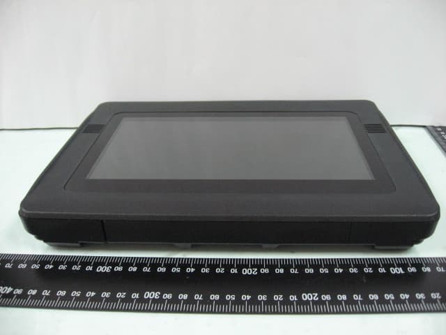
Click to zoom
Application Details
- Equipment Class
- DTS - Digital Transmission System
- Date of Grant
- Jan 16, 2013
- Application Purpose
- Original Equipment
- Date of Application
- Jan 16, 2013
- Equipment Note
- Mr. MENU (Menu Terminal)
- Frequency Range
- 2412.00000000 - 2462.00000000
- Company
- Worldpicom Corporation
- Country
- Japan
Documents & Files
Document Text
Text extracted from the exhibit documents filed with the FCC. Open a document above to read the original.
Users Manual
0 Table Terminal WP-D701 OST CradleWP-C424A OSH CradleWP-C521A Rev.20121206_R4 Table Top Order System User's manual Importer: Global Network Resources, Inc. Address: 2241 Calle de Luna, Santa Clara, CA 95054 1 Chapter 1. Terminal switch operation When the condition of the Terminal is not good, it may be improved by ON/OFF of the main switch. [Example] • Display screen does not change when you check-in or check-out. • There is no response to touch a button on the screen that you want to order (It seems like “freeze”) • Even if the "clear error" from the MIS, will not stop flashing red. (communication error) • Do not be started. Note: Please do not touch except when trouble shooting as much as possible. At the top right side of the Terminal, there's a hole 0.5 ~ 1 mm, it is the power switch. Please don’t use except when dealing with trouble. The above switches, use the dedicated reset pin. Power switch Enlarged view 2 Chapter 2. Details of the front lower left side lamp Two Power light Description (Left and Right) (Left) Green light...Power ON, State is placed on the cradle, Ready for communication. Green light blink ...Power ON, State is placed not on the cradle, Ready for communication. Red light or blink...State is can not communication. Unlitght...State is Power OFF. Note: The wireless device is not working, until when you choose “Operational mode” please read more information on next page . (Right) Orange light...Charging, State is on the cradle. Unlitght...State is Fully charged. 3 Chapter 3. After start-up mode selection Cradle (1) Please wait until this screen appears when you turn on the power switch. Then you can choose "Setting mode“, "Training mode" and "Operation mode". (2) When you choose "Setting mode" can be adjusted for volume tune, brightness or other condition of the terminal. (3) When you choose "Training mode" the menu can be operated as a stand-alone terminal demo. The wireless network device is not working. (4) When you choose “Operational mode” the terminal working on actual system environment with wireless network device. (5) Please note that you can not start if there is no actual system environment wireless network for "Operation mode". Desktop type WP-C424A Wall-mounted type WP-C521A This cradle designed for safety, voltage is only output from electric pin when the terminal state put on it . When put on the cradle, the terminal will charge. 4 Chapter 4. Products Specifications Table Terminal Model: WP-D701 Dimension: 300mm(W)×219mm(H)×40mm(D) Weight: 1.2kg, 1.4kg (Option battery Operating) Display: 10.1 WSVGA 1024×600 (200cd/m2) Horizontal: 45°45° Vertical: 20°45° WiFi : IEEE-802.11b & g Power: DC12V, 10W or less power consumption form built-in battery Built-in battery: 6hours, Option battery Operating 12hours (At the lowest brightness setting) Charging method: Charging by dedicated cradle, DC input from AC adapter. Touch screen: Projective Capacitive(multi-touch) OS: LINUX 2.6.32 Wireless device (Inside Table Terminal) ・Operational frequency: 2412 to 2462 MHz (5MHz step, 11 channels) ・IEEE802.11 b/g compliant Wireless LAN ・Data rate IEEE802.11b: 1, 2, 5.5 and 11 Mbps IEEE802.11g: 6, 9, 12, 18, 24, 36, 48 and 54 Mbps Cradle Model: OST Cradle (WP-C424A) and OSH Cradle(WP-C521A) Input/Output voltage: DC 12V2A Battery Model: 2UR18650-2-WRPC Classification of the battery: Lithium Ion Battery Rated voltage: 7.4V Capacity: Typical 4800mA / Lowest 4600mA Battery Type: 2UR18685F-2 Manufacturers: STANDARD ELECTRIC CO., LTD 5 Chapter 5. Operating Considerations (§2.1077(a)(1)) Company: Worldpicom Corporation Model name: Table Terminal Model number: WP-D701 FCC ID: PRTJD712 (§2.1077(a)(3), §2.909) Subsidiary of the U.S. information: Global Network Resources, Inc. Address: 2241 Calle de Luna, Santa Clara, CA 95054 Phone: 408.727.1900 / Fax: 408.727.1910 (§15.21) Notice: The changes or modifications not expressly approved by the party responsible for compliance could void the user’s authority to operate the equipment. IMPORTANT NOTE: To comply with the FCC RF exposure compliance requirements, no change to the antenna or the device is permitted. Any change to the antenna or the device could result in the device exceeding the RF exposure requirements and void user’s authority to operate the device. (§15.105) FCC INFORMATION The Federal Communication Commission Radio Frequency Interference Statement includes the following paragraph: NOTE: This equipment has been tested and found to comply with the limits for a Class B digital device, pursuant to part 15 of the FCC Rules. These limits are designed to provide reasonable protection against harmful interference in a residential installation. This equipment generates, uses and can radiate radio frequency energy and, if not installed and used in accordance with the instructions, may cause harmful interference to radio communications. However, there is no guarantee that interferencewill not occur in a particular installation. If this equipment does cause harmful interference to radio or television reception, which can be determined by turning the equipment off and on, the user is encouraged to try to correct the interference by one or more of the following measures: —Reorient or relocate the receiving antenna. —Increase the separation between the equipment and receiver. —Connect the equipment into an outlet on a circuit different from that to which the receiver is connected. —Consult the dealer or an experienced radio/TV technician for help. The user should not modify or change this equipment without written approval form Worldpicom Corporation. Modification could void authority to use this equipment. This device complies with part 15 of the FCC Rules. Operation is subject to the following two conditions: (1) This device may not cause harmful interference, and (2) this device must accept any interference received, including interference that may cause undesired operation.
Cover Letter(s)
Date: October 17, 2012 Compliance Certification Services Certification Division 47173 Benicia Street Fremont, CA 94538, USA To whom it may concern: We, the undersigned, hereby authorize ELECTRONICS TESTING CENTER, TAIWAN, to act on our behalf in all manners relating to application for equipment authorization, including signing of all documents relating to these matters. Any and all acts carried out by ELECTRONICS TESTING CENTER, TAIWAN on our behalf shall have the same effect as acts of our own. We, the undersigned, hereby certify that we are not subject to a denial of federal benefits, that includes FCC benefits, pursuant to Section 5301 of the Anti-Drug Abuse Act of 1988, 21 U.S.C. 853(a). In authorizing ELECTRONICS TESTING CENTER, TAIWAN as our agent, we still recognize that we are responsible to: a) comply with the relevant provisions of the certification program; b) make all necessary arrangements for the conduct of the evaluation, including provision for examining documentation and access to all areas, records (including internal audit reports) and personnel for the purposes of evaluation (e.g. testing, inspection, assessment, surveillance, reassessment) and resolution of complaints; c) make claims regarding certification only in respect of the scope for which certification has been granted; d) do not use our product certification in such a manner as to bring the Certification Division into disrepute and not make any statement regarding our product certification which the Certification Division may consider misleading or unauthorized; e) upon suspension or cancellation of certification, discontinue use of all advertising matter that contains any reference thereto and return any certification documents as required by the Certification Division; f) use certification only to indicate the products are certified as being in conformity with specified standards; g) endeavor to ensure that no certificate or report nor any part thereof is used in a misleading manner; h) ensure that any reference to our product certification in communication media such as documents, brochures or advertising, complies with the requirements of the Certification Division; i) keep a record of all complaints made known to the us relating to the product’s compliance with requirements of the relevant standard and to make these records available to the Certification Division when requested; j) take appropriate action with respect to such complaints and any deficiencies found in products or services that affect compliance with the requirements for certification; k) document the actions taken. This authorization is valid until further written notice from the applicant. Sincerely Yours, (signature) Name: Toshifumi Anazawa Title: International Business Development Manager Company: Worldpicom Corporation Address: Yokohama Landmark Tower 9F,2-2-1, Minatomirai, Nishi-ku Yokohama-shi, Kanagawa 220-8109 JAPAN Tel: +81-45-277-2668 Fax: +81-45-277-2660
Cover Letter(s)
Federal Communications Commission FCC ID: PRTJD712 Product Name: Mr. MENU Model Name: WP-D701 Trade Name: Worldpicom Corporation Dear Sir: In accordance with 47 C.F.R. Section 0.459, we would like to request confidentiality on some exhibits we submitted for above application for the reason of trade secret. If those exhibits are available for public inspection, any person who once gets the information contained in those exhibits will be able to design and to make the same products very easily. This is a very serious problem and huge loss for us, because we did invest so much on it. Please be not made the Exhibit Types listed below routinely available for public inspection: Block Diagram and Schematics and Operation Description. By: By: Toshifumi Anazawa (representative Signature) (representative Printed) Title : International Business Development Manager Applicant : Worldpicom Corporation Address : Yokohama Landmark Tower 9F,2-2-1, Minatomirai, Nishi-ku, Yokohama-shi, Kanagawa 220-8109 JAPAN Tel : +81-45-277-2668 Fax: +81-45-277-2660 Date : October 17, 2012
External Photos
ETC Report No. : 12-08-RBF-013-01 FCC ID: PRTJD712 Sheet 1 of 10 Sheets Rev. No 2.1 CONSTRUCTED PHOTOS of EUT 1. 2. ETC Report No. : 12-08-RBF-013-01 FCC ID: PRTJD712 Sheet 2 of 10 Sheets Rev. No 2.1 CONSTRUCTED PHOTOS of EUT 3. 4. ETC Report No. : 12-08-RBF-013-01 FCC ID: PRTJD712 Sheet 3 of 10 Sheets Rev. No 2.1 CONSTRUCTED PHOTOS of EUT 5. 6.
ID Label/Location Info
XyymXXXX**** This device complies with part 15 of the FCC Rules. Operation issubject to the following two conditions: (1) This device may not cause harmful interference, and (2) this device must accept any interference received, includinginterference that may cause undesired operation. Worldpicom Corporation Model: WP-D701 MADE IN CHINA FCC ID: PRTJD712 CAN ICES-3(B)/NMB-3(B)IC: 10528A-JD712 JAPAN VIETNAM RESTAURANT JOINT STOCK COMPANY CODE: A0729310812AE01A2 R001WWCA1305 2.4 DS/OF 4 S/No X00000 XXXX00XX0000X0 FCC, IC and ICT Label 128mm 59mm 300mm(W)×219mm(H)×40mm(D) 96mm 64mm 59mm 128mm 86mm86mm FCC ID: PRTJD712
Internal Photos
ETC Report No. : 12-08-RBF-013-01 FCC ID: PRTJD712 Sheet 4 of 10 Sheets Rev. No 2.1 CONSTRUCTED PHOTOS of EUT 7. 8. ETC Report No. : 12-08-RBF-013-01 FCC ID: PRTJD712 Sheet 5 of 10 Sheets Rev. No 2.1 CONSTRUCTED PHOTOS of EUT 9. 10. ETC Report No. : 12-08-RBF-013-01 FCC ID: PRTJD712 Sheet 6 of 10 Sheets Rev. No 2.1 CONSTRUCTED PHOTOS of EUT 11. ETC Report No. : 12-08-RBF-013-01 FCC ID: PRTJD712 Sheet 7 of 10 Sheets Rev. No 2.1 CONSTRUCTED PHOTOS of EUT 12. 13. ETC Report No. : 12-08-RBF-013-01 FCC ID: PRTJD712 Sheet 8 of 10 Sheets Rev. No 2.1 CONSTRUCTED PHOTOS of EUT 14. 15. ETC Report No. : 12-08-RBF-013-01 FCC ID: PRTJD712 Sheet 9 of 10 Sheets Rev. No 2.1 CONSTRUCTED PHOTOS of EUT 16. 17. ETC Report No. : 12-08-RBF-013-01 FCC ID: PRTJD712 Sheet 10 of 10 Sheets Rev. No 2.1 CONSTRUCTED PHOTOS of EUT 18. 19.
Parts List/Tune Up Info
SET_DSK0703B Apr 22, 2011 Murata Proprietary, Murata Confidential - 1 - Technical Data Sheet Of BT/WLAN Antenna on Standard PWB Note Please confirm the latest specification for antenna shape and dimensions. Capacitors and Inductors used in this report are as follows unless otherwise specified. The values of each components are mentioned in the report. In case using different series or manufactures' components, another value may be required to get the proper result. Capacitors: GRM15 series (Murata) Inductors: LQG15HS series (Murata) Kanazawa Murata Mfg.Co.,Ltd Antenna Products Department P/N : ANCG12G44SAA145RD1 PWB size : 37x80mm SET_DSK0703B Apr 22, 2011 Murata Proprietary, Murata Confidential - 2 - Measurement condition ANCG12G44SAA145RD1:2x9.8xt3.8mm(L turn) / PWB 37x80mm 0.5pF 12nH SET_DSK0703B Apr 22, 2011 Murata Proprietary, Murata Confidential - 3 - Measurement direction horizontal vertical Z (0deg) Y (90deg) X Y ZX plane Z (0deg) X (90deg) Antenna YZ plane Antenna 3D Measurement Stargate32 (Satimo) SET_DSK0703B Apr 22, 2011 Murata Proprietary, Murata Confidential - 4 - Measurement result Return loss Fig. 1 Condition 1: ANCG12G44SAA145RD1 Antenna gain(3D measurement) Table. 1 Condition 1: ANCG12G44SAA145RD1 [dBi][dB] hor. ver. hor. ver. MAX 0.4 -7.5 -1.6 -0.4 AVE -3.4 -10.1 -8.0 -3.2-2.1 MAX0.7-6.6-1.30.2 AVE -3.0 -9.6 -7.3 -2.6 -1.6 MAX-0.5-7.4-2.0-0.5 AVE-3.6-10.4-7.9-3.2-2.2 MHz 2442 MHz 2484 MHz LINEAR YZ-plane Efficiency POLARIZATION 2400 ZX-plane Radiation Pattern(3D measurement) YZ planeZX plane HOR. VER.HOR. VER. MAX 0.7 -6.6MAX -1.3 0.2 AVE-3.0-9.6AVE-7.3-2.6 -30 -25 -20 -15 -10 -5 0 0 90 180 270 horizontal vertical -30 -25 -20 -15 -10 -5 0 0 90 180 270 horizontal vertical Fig. 2 Condition 1: ANCG12G44SAA145RD1
RF Exposure Info
Statement of Justification and Compliance for SAR Test Exclusion Product: Mr. MENU (Menu Terminal) FCC ID: PRTJD712 Manufacturer: Worldpicom Corporation Brand: Worldpicom Corporation Model: WP-D701 According to FCC KDB 447498 D01 General RF Exposure Guidance v05 4.3.1. Standalone SAR test exclusion considerations 1) The 1-g and 10-g SAR test exclusion thresholds for 100 MHz to 6 GHz at test separation distances ≤ 50 mm are determined by: [(max. power of channel, including tune-up tolerance, mW)/(min. test separation distance, mm)] · [√f (GHz)] ≤ 3.0 for 1-g SAR and ≤ 7.5 for 10-g extremity SAR, 16 where f(GHz) is the RF channel transmit frequency in GHz Power and distance are rounded to the nearest mW and mm before calculation The result is rounded to one decimal place for comparison The test exclusions are applicable only when the minimum test separation distance is ≤ 50 mm and for transmission frequencies between 100 MHz and 6 GHz. When the minimum test separation distance is < 5 mm, a distance of 5 mm is applied to determine SAR test exclusion. For the present device, the declared output power is 13dBm with +/- 0.5dB tolerance. So, max. power of channel, including tune-up tolerance = 22.387 mW (13.5dBm) min. test separation distance = 12 mm f(GHz) = 2.462 [(max. power of channel, including tune-up tolerance, mW)/(min. test separation distance, mm)] · [√f(GHz)] = (22.387 / 12) · (√2.462) = 2.9 ≤ 3.0 Hence the SAR Exclusion Threshold condition is satisfied and the SAR evaluation for general population exposure conditions is not required.
Test Report
Rev. No 2.0 FCC Part 15 EMI TEST REPORT of E.U.T. : Mr. MENU (Menu Terminal) Model No. : WP-D701 FCC ID. : PRTJD712 for APPLICANT : Worldpicom Corporation ADDRESS : Yokohama Landpark Tower 9F,2-2-1, Minatomirai, Nishi-ku,Yokohama-shi, Kanagawa 220-8109 JAPAN Test Performed by ELECTRONICS TESTING CENTER, TAIWAN NO. 34. LIN 5, DINGFU VIL., LINKOU DIST., NEW TAIPEI CITY, TAIWAN, 24442, R.O.C Tel : (02)26023052 Fax : (02)26010910 http://www.etc.org.tw ; e-mail: [email protected] Report Number : 12-08-RBF-013-01 ETC Report No. : 12-08-RBF-013-01 FCC ID: PRTJD712 Rev. No 1.0 TEST REPORT CERTIFICATION Applicant : Worldpicom Corporation Yokohama Landpark Tower 9F,2-2-1, Minatomirai, Nishi- ku,Yokohama-shi, Kanagawa 220-8109 JAPAN Manufacturer : Worldpicom Corporation Yokohama Landpark Tower 9F,2-2-1, Minatomirai, Nishi- ku,Yokohama-shi, Kanagawa 220-8109 JAPAN Description of EUT a) Type of EUT Mr. MENU (Menu Terminal) b) Trade Name Worldpicom Corporation c) Model No. WP-D701 d) Power Supply : : : : 3.3Vdc from host equipment Adapter for host equipment: I/P:100-240V,47~63Hz,0.7A O/P:12V,2.5A Regulation Applied : FCC Rules and Regulations Part 15 Subpart C I HEREBY CERTIFY THAT: The data shown in this report were made in accordance with the procedures given in ANSI C63.4, and the energy emitted by the device was founded to be within the limits applicable. I assume full responsibility for accuracy and completeness of these data. Note: 1. The result of the testing report relate only to the item tested. 2. The testing report shall not be reproduced expect in full, without the written approval of ETC. Summary of Tests Test Results Radiated Emission Pass Conducted Emission Pass Emission Bandwidth Pass Output Power Pass 100 kHz Bandwidth of Band Edges Pass Power Density Pass Out-of-Band Conducted Emission Pass ETC Report No. : 12-08-RBF-013-01 FCC ID: PRTJD712 Rev. No 1.0 Date Test Item Received : Aug. 13, 2012 Date Test Campaign Completed : Nov. 13, 2012 Date of Issue : Dec. 26, 2012 Test Engineer : ( Vincent Chang, Engineer ) Approve & Authorized : S. S. Liou, Section Manager EMC Dept. II of ELECTRONICS TESTING CENTER, TAIWAN ETC Report No. : 12-08-RBF-013-01 FCC ID: PRTJD712 Rev. No 1.0 Table of Contents Page 1 GENERAL INFORMATION ....................................................................................................... 1 1.1 Product Description...................................................................................................................... 1 1.2 Characteristics of Device ............................................................................................................. 1 1.3 Test Methodology ........................................................................................................................ 1 1.4 Test Facility.................................................................................................................................. 1 2 PROVISIONS APPLICABLE...................................................................................................... 2 2.1 Definition ..................................................................................................................................... 2 2.2 Requirement for Compliance ....................................................................................................... 3 2.3 Restricted Bands of Operation ..................................................................................................... 5 2.4 Labeling Requirement .................................................................................................................. 5 2.5 User Information .......................................................................................................................... 6 3. SYSTEM TEST CONFIGURATION .......................................................................................... 7 3.1 Justification .................................................................................................................................. 7 3.2 Devices for Tested System........................................................................................................... 7 4 RADIATED EMISSION MEASUREMENT .............................................................................. 8 4.1 Applicable Standard ..................................................................................................................... 8 4.2 Measurement Procedure............................................................................................................... 8 4.3 Measuring Instrument ................................................................................................................ 10 4.4 Radiated Emission Data ............................................................................................................. 11 4.5 Field Strength Calculation ......................................................................................................... 25 4.6 Photos of Radiation Measuring Setup........................................................................................ 26 5 CONDUCTED EMISSION MEASUREMENT ........................................................................ 29 5.1 Standard Applicable ................................................................................................................... 29 5.2 Measurement Procedure............................................................................................................. 29 5.3 Conducted Emission Data .......................................................................................................... 31 5.4 Result Data Calculation ............................................................................................................. 35 5.5 Conducted Measurement Equipment ......................................................................................... 35 5.6 Photos of Conduction Measuring Setup...................…
Text truncated - open the document above for the full version.
Test Setup Photos
ETC Report No. : 12-10-RBF-028-05 FCC ID: PRTJD712 Sheet 26 of 77 Sheets Rev. No 2.0 4.6 Photos of Radiation Measuring Setup Test Mode: WIFI & FULL SYSTEM WORKING MODE (Signal Mode) ETC Report No. : 12-10-RBF-028-05 FCC ID: PRTJD712 Sheet 27 of 77 Sheets Rev. No 2.0 Test Mode: CHARGE & Operation MODE (Desktop type:WP-C424A) ETC Report No. : 12-10-RBF-028-05 FCC ID: PRTJD712 Sheet 28 of 77 Sheets Rev. No 2.0 Test Mode: CHARGE & Operation MODE (Wall-mounted type:WP-C424A) ETC Report No. : 12-10-RBF-028-05 FCC ID: PRTJD712 Sheet 36 of 77 Sheets Rev. No 2.0 5.6 Photos of Conduction Measuring Setup Test Mode: CHARGE & Operation MODE(Desktop type:WP-C424A) ETC Report No. : 12-10-RBF-028-05 FCC ID: PRTJD712 Sheet 37 of 77 Sheets Rev. No 2.0 Test Mode: CHARGE & Operation MODE(Wall-mounted type:WP-C424A)
Contact Information
Applicant
Toshifumi Anazawa(International Business Development Manager)
Technical Contact
ELECTRONICS TESTING CENTER, TAIWANS.S. LIOU
[email protected]886-2-26023052
NO. 34, LIN 5, DINGFU TSUEN, LINKOU SHIANG, · Taipei County · Taiwan
Test Firm
Taiwan Testing and Certification CenterAnderson Ku
Technical Specifications
| # | Rule Parts | Frequency Range | Power Output |
|---|---|---|---|
| 2 | 15C | 2.41 GHz - 2.46 GHz | 17.00 mW |
Other Applications from Worldpicom Corporation
PRTWP-D801
Mar 08, 2015Table Terminal
Equipment Class
DXX - Part 15 Low Power Communication Device Transmitter