PS3T2000Transponder
Microair Avionics PTY LTD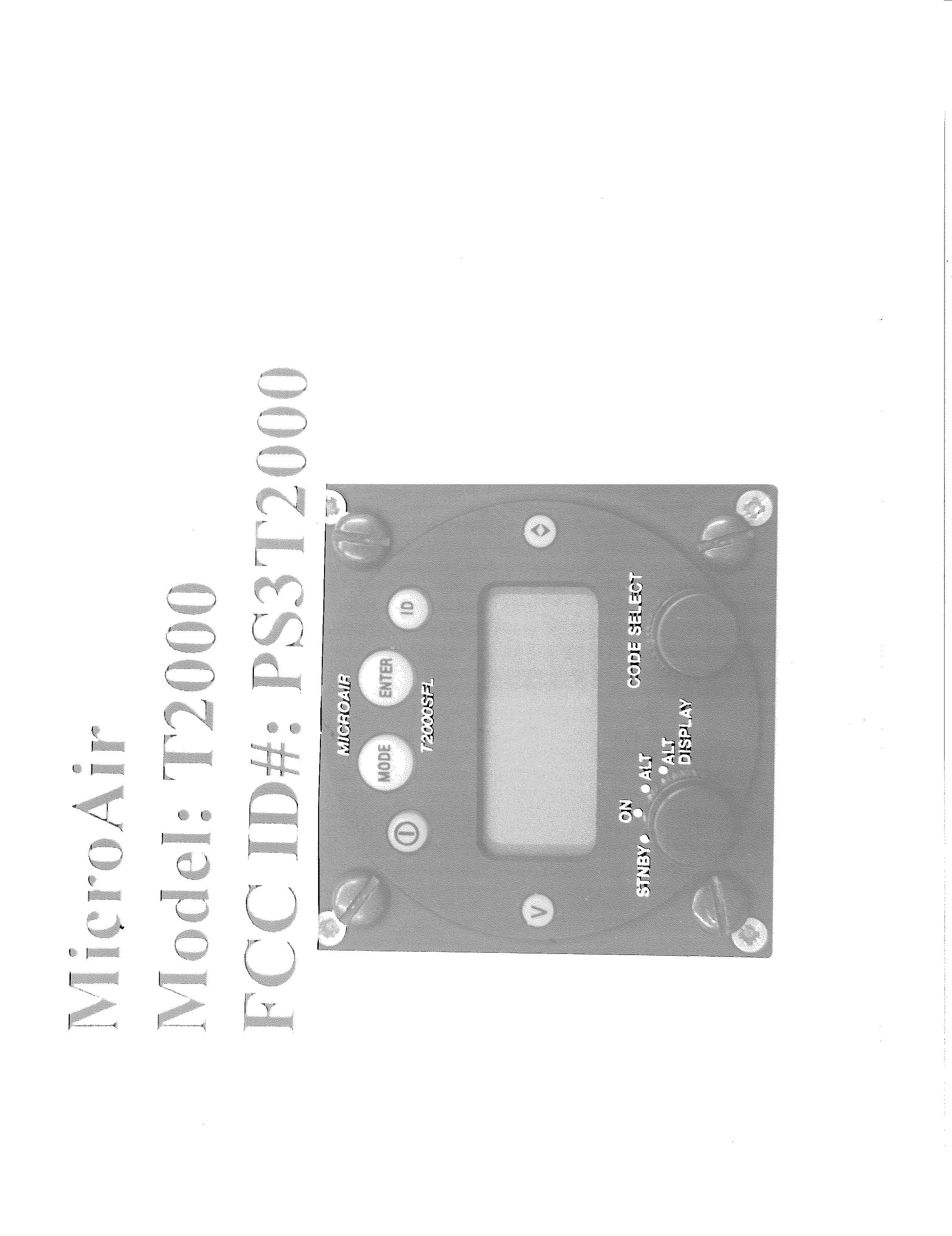
Click to zoom
Application Details
- Equipment Class
- TNB - Licensed Non-Broadcast Station Transmitter
- Date of Grant
- Nov 04, 2001
- Application Purpose
- Original Equipment
- Date of Application
- Aug 20, 2001
- Equipment Note
- Transponder
- Frequency Range
- 960.00000000 - 1215.00000000
- Company
- Microair Avionics PTY LTD
- Country
- Australia
Documents & Files
Document Text
Text extracted from the exhibit documents filed with the FCC. Open a document above to read the original.
Users Manual
Microair Avionics T2000 Transponder User Manual Version 2.0 Page 1 11/02/01 Microair Avionics PTY Ltd Airport Drive Bundaberg Queensland 4310 Australia Tel: +61 7 41 553048 Fax: +61 7 41 553049 e-mail: [email protected] Microair Avionics T2000 Transponder User Manual Version 2.0 Page 2 11/02/01 About This Document Microair Avionics have developed a series of transponders for use with OEM applications, and for commercial sale by Microair Avionics. The manual explains the basic functions and elaborates on the more sophisticated features, such as altitude display and alerts. Microair reserve the right to amend this manual as required, to reflect any enhancements or upgrades to the T2000 Transponder series. © Microair Avionics PTY Ltd Statement: The T2000SF/SFL owner accepts all responsibility for obtaining the proper licensing before using the transponder. The coverage you can expect from the T2000SF/SFL is limited to “line of sight”. Low altitude or aircraft antenna shielding by the aircraft itself may result in a reduced range. Range can be improved by climbing to a higher altitude. It may be possible to minimize antenna shielding by locating the antenna where dead spots are only noticed during abnormal flight attitudes. The T2000SF/SFL should be turned off before starting or shutting down aircraft engine(s). MICROAIR DOCUMENTS Microair T2000 Users Manual T2000-DOC-001 Microair T2000 Installation Manual T2000-DOC-002 Microair T2000 Flight Manual Supplement T2000-DOC-003 Microair T2000 Service Manual T2000-DOC-004 DOCUMENT REVISION STATUS – T2000-DOC-001 Revision Date Change 1.0 11/02/01 Initial Draft 2.2 11/7/01 Voltage Monitoring Microair Avionics T2000 Transponder User Manual Version 2.0 Page 3 11/02/01 TABLE OF CONTENTS ABOUT THIS DOCUMENT.............................................................................................................................2 MICROAIR DOCUMENTS ..............................................................................................................................2 DOCUMENT REVISION STATUS – T2000-DOC-001...................................................................................2 INTRODUCTION..............................................................................................................................................4 OPERATION.........................................................................................................................................6 T2000 SF/SFL ...........................................................................................................................6 DISPLAY FUNCTION ......................................................................................................................................7 T2000SF ................................................................................................................................................7 T2000SFL ..............................................................................................................................................7 CONTROLS FUNCTIONS................................................................................................................................9 SELECTMODE KNOB .........................................................................................................................9 CODE ADJUST KNOB.......................................................................................................................10 ON KEY ..............................................................................................................................................10 MODE KEY ........................................................................................................................................11 QNH ENTRY ( BAROMETER SETTING )...........................................................................11 ASSIGNED ALTITUDE.........................................................................................................12 ASSIGNED BUFFER .............................................................................................................12 ALTITUDE UNITS.................................................................................................................13 VOLTAGE ( VOLTAGE SETPOINTS , RECEIVE VOLTS )...............................................13 BEEP .......................................................................................................................................13 ENTER KEY .......................................................................................................................................14 < > KEY..............................................................................................................................................14 VFR – HOT KEY ................................................................................................................................15 ID KEY................................................................................................................................................15 INITIALISATION AND SETUP.....................................................................................................................16 PROGRAM MODE .............................................................................................................................16 NAME & REGISTRATION (ONE TIME ONLY ENTRY)...................................................16 VOLTAGE ..............................................................................................................................17 ENCODER POWER ...............................................................................................................17 DISPLAY BRIGHT ( SF MODEL ONLY ) ...........................................................................18 DISPLAY TIMEOUT ( SF MODEL ONLY ) ........................................................................19 BARO…
Text truncated - open the document above for the full version.
Cover Letter(s)
FCC ID: PS3T2000 MFA p0170009, d0180059 Date of Report: Date of Submission: August 15, 2001 August 20, 2001 Federal Aviation Administration Spectrum Engineering Division ASR-1 800 Independence Ave. S.W. Washington, D.C. 20591 Attention: Annette Allender (202) 267-3893 Applicant: Microair Avionics PTY LTD Equipment: FCC ID: PS3T2000 FCC Rules: 87 Gentlemen: As required under FCC Rule Part 87.147(d) please consider this letter, sent on behalf of the Applicant, as notification of the filing of an application Form 731 for the certification of the referenced equipment. Attached for your records, please find: 1. copy of the FCC Application Form 731 2. copy of the proof of electronic filing to FCC with EA# 3. copy of the covering letter to the Commission 4. copy of the Agent Authorization letter for the writer to act on behalf of the Applicant. 5. Copy of Test Report as sent to the FCC We trust the enclosed complies with your requirements. Should you need any further clarification, kindly contact the writer. Sincerely yours, Morton Flom, P. Eng. MF/cvr enclosure(s) cc: Applicant cc: FCC via Electronic Filing cc: Industry Canada VIA CERTIFIED MAIL
Operational Description
Microair Avionics – Commercial in Confidence Document version 1.5 T2000 PRODUCTION ASSEMBLY MANUAL Page6of 89 Theory of Operation. Introduction The T2000 series of transponders are designed to operate within the Air Traffic Control radar environment. The design criteria was for a high performance unit that was lightweight, low power consumption and suited a range of aircraft. The chassis is split into 3 cavities , the main , the transmitter and the micro controller. Chassis construction is off CNC milled aluminium. Receiver. Signals are received via the BNC antenna input socket and passed into the RX / TX port of the circulator. As the receive port is first off the circulator this signal is then fed into the band pass filter for filtering the resultant 1030 Mhz signal. This signal is then fed into the receiver board which consists of an LNA , receiver chip , 5 volt regulator and op amp. The LNA is programmed to boost the filtered 1030 signal a further 10 DB before passing it on to the Receiver chip. The receiver chip uses logarithmic amplifiers to detect the signal over a –73 dbm range , the output has a swing from .6 of a volt ( least sensitivity ) to + 2 volts ( maximum sensitivity ) and is linear. The following op amp acts a buffer / edge detector before presenting the analog voltage to the micro processor . An additional comparator provides pulse width measurement which is fed into the input compare port on the micro controller, as well as a start of conversion pulse for the flash A to D converter. Transmitter. The transmitter consists of 3 stages : Oscillator Buffer / Driver Power Amplifier The oscillator consists of a tuned resonator at 1090 Mhz , volts are applied ( pulsed ) at the emitter via a monastable triggered by the micro controller.The resonator sets the transmit frequency .The base is biased, also a variable capacitor at the base provides frequency adjustment. The collector of the oscillator is also switched at the same time , this provides 52 volts. The resultant 1090 signal ( approximately 12 watts ) is then fed into the buffer amplifier and final P.A . Both stages are in class C. A series of ¼ wave matching stubs on the output provide 2 nd , 3 rd , 4 th and 5 th harmonic suppression. Power Supply. The power supply has 2 onboard regulators, one running in Boost mode to switch the 10 to 33 volts D.C input up to 52 volts ( transmitter volts ) and the other is a 8 volt regulator which supplies power to the receiver. The input is over voltage and reverse power protected. 5 volts for the micro controller is derived from an onboard ( main micro board ) switchmode regulator which is not switched of from the power in ( live to the input ) . The switch mode for the 8 and 50 volts is switched on and off by the main micro controller. Microair Avionics – Commercial in Confidence Document version 1.5 T2000 PRODUCTION ASSEMBLY MANUAL Page7of 89 Micro processor ( Main board ) The micro controller is a 17c756 OTP , an econ reset power monitor will reset the micro controller should an unstable supply voltage be detected. A watchdog timer which is internal to the micro controller provides software and hardware monitoring and reset should there be a failure, also an external power watchdog provides a clean reset should the volts to the micro drop by 10%. The receiver analog volts is fed into a 10 bit , A to D chip. The output is then fed into the 8 bit port ( Port F ) on the micro controller. The signal is then processed and a valid reply sent should the A or C interrogation be received. Additional to processing the receiver , the micro also sends the transmit pulses to the monostable at the transmitter oscillator. Gillham altitude information is processed by the micro controller as 10 bit data received at port C and D. This is then displayed on the ALT DISP and also transmitted in the mode C transmission.. Other inputs and outputs include: Remote ID – An input to this pin going low will initiate an ID transmission ( SPI Pulse ). Remote standby- An input to this pin going low will initiate a standby condition on the T2000 , the S symbol will be displayed. Suppression In – and high input ( 5 to 33 volts ) will suppress the T2000 transmit pulses for the duration of the high status. Suppression out – The T2000 will toggle this pin high every time a transmission occurs. The pulse is low going high ( TTL – 5 volts ). Encoder volts – A switched output for driving an external altitude encoder , volts out follow volts in at the power input , i.e A 28 volt input will provide 28 volts out to the encoder, 14 volts in will provide 14 volts out. RS-485 + and - - RS-485 data line for connection to external displays and MFD’s ( future development ). A to D monitoring of the power input provides BUS voltage display , also a to d monitoring of the receiver volts provides a diagnostic tool for monitoring the receiver volts. The internal communications from the display to the main micro is via an RS – 232 link. Micro controller ( SF Display ) The display can be used as a master or remote. Communications is provided by RS –232 ( for internal connection ).The micro controller is a 17c756 OTP , an econ reset power monitor will reset the micro controller should an unstable supply voltage be detected. Also this reset IC acts as a watchdog timer which provides hardware monitoring and reset should there be a failure. 2 x 8 line Alphanumeric displays are serially addressed by the micro controller. The displays have their own drivers and character generators. LED display brightness levels are controlled by a photo resistor which is monitored by the micro controllers A to D. Keyswitch inputs are scanned by the micro and initiated when depressed. These inputs are: On/OFF – Sends the on / off request to the main micro controller , also provides the keypad backlight command. Mode: Selects various mode commands ( see user manual ) Enter: Enter key ID – Sends SPI ( IDENT ) command to main micro controller. VFR – Sends sto…
Text truncated - open the document above for the full version.
Parts List/Tune Up Info
Microair Avionics – Commercial in Confidence Document version 1.5 T2000 PRODUCTION ASSEMBLY MANUAL Page83of 89 Bill of Materials Introduction. The Bill of materials covers all versions of the T2000 series. T2000 Bill of Materials ( BOM ) All resistors 1% tolerance unless specified different. Assy Qty Designator Manuf P/N Description RF Section Receiver Rx 1 RIC2 AD8313ARM Logarithmic Detector, 2.5GHz 70dB Rx 1 RIC1 LP2951aCM Voltage Regulator, SO-8 Rx 2 RIC3RIC4 AD8052ARM Op Amp Rx 1 RIC5 74HC04UB Hex Inverting Buffers SO-8 Rx 1 RTR1 HPFP0405 LNA AGILENT Rx 6 RC6,RC10,RC13,RC16 RC17,RC18 100N CAP, 100N SMD 50V X7R 10% 0805 Rx 2 RC4 RC5 1N CAP 1nF SMD 50V NPO 10% 0805 Rx 1 RC3 1P0 CAP 1pF SMD 50V NPO 10% 0805 Rx 2 RC1 RC8 1p8 CAP 1p8 SMD 50V NPO 10% 0805 Rx 2 RC9 RC12 3p3 CAP 3p3 SMD 50V NPO 10% 0805 Rx 3 RC2 RC11 RC14 47p CAP 47pF SMD 50V NPO 10% 0805 Rx 2 RC15 RC7 10UF Tantalum, 10UF 10V, B size Rx 1 RL1 470nH 470nH inductor 1206 case Rx 3 RL2 RL3 RL4 8n2 8n2 inductor 0805 case Rx 5 RR10 RR12 RR15 RR25 RR27 10R Resistor, 0805 125mW METAL 1% 0805 Rx 5 RR1 RR2 RR4 RR24 RR26 47R Resistor, 0805 125mW METAL 1% 0805 Rx 1 RR11 470R Resistor, 0805 125mW METAL 1% 0805 Rx 1 RR13 1k5 Resistor, 0805 125mW METAL 1% 0805 Rx 5 RR6 RR7 RR9 RR14 RR17 1K Resistor, 0805 125mW METAL 1% 0805 Rx 4 RR19 RR20 RR21 RR23 4K7 Resistor, 0805 125mW METAL 1% 0805 Rx 4 RR8 RR16 RR18 RR28 10K Resistor, 0805 125mW METAL 1% 0805 Rx 1 RR3 15K Resistor, 0805 125mW METAL 1% 0805 Rx 1 RR5 100K Resistor, 0805 125mW METAL 1% 0805 Rx 2 RRV1,RRV2 10k trimpot 10 k multurn trimpot Bournes 10k3224w Transmitter Tx 1 TIC1 MM74HC221AM Dual Monostable Multivibrator SO-16 Tx 2 TTR2,TTR3 1090MP 90 watt pulsed RF Transistor 1030 - 1090 Mhz, GHZ Tx 1 TTR4 TPR175 175 watt pulsed RF Transistor 1030 - 1090 Mhz,GHZ Tx 1 TTR1 NDS355AN MOSFET, N-ch, 30V 1.7A, SOT-23 Tx 1 TD4 ZR2431F01/431l Adjust Volt Reg Zetek ZR2431F01 or 431L Tx 1 TD3 BAT54 High Speed Diode SOT-23 Tx 1 TD2 33V 33V Zener BZX85C33 1.3W, DO-41 Tx 1 TD1, 27V 27V Zener BZX85C27 1.3W, DO-41 Tx 1 TC27 (CT1) A1J8 Capacitor, Variable, 0.5-8p, Air Diel Voltronics Tx 1 TC36 (CT2) GIGATRIM Capacitor, Variable, .3-1.2p , Air Dielectric Johansen Tx 2 TC5 TC3 47uF Electrolytic capacitor, 47u 63V, –40 to + 105 Microair Avionics – Commercial in Confidence Document version 1.5 T2000 PRODUCTION ASSEMBLY MANUAL Page84of 89 Tx 1 TC37 4u7 CAP 4.7Uf SMD 16V TANT 10% CASE B –40 to +105 Tx 1 TC35 100u CAP 100Uf SMD 16V TANT 10% 2816 –40 to +105 Tx 5 TC2,TC18,TC26,TC34, TC44 100n CAP, 100N SMD 63V X7R 10% 0805 Tx 5 TC1,TC13,TC21,TC30, TC38 10n CAP 10nF SMD 63V NPO 10% 0805 Tx 4 TC14,TC24,TC29,TC42 1n CAP 1nF SMD 63V NPO 10% 0805 Tx 1 TC23 3p9 CAP 3p9 SMD 50V NPO 10% 0805 Tx 1 TC28 4p7 CAP 4p7 SMD ATC HIGH VOLTAGE 0805/1206 Tx 4 TC11,TC15,TC17,TC25 5p6 CAP 5p6 SMD 50V NPO 10% 0805 Tx 2 TC12,TC19 6p8 CAP 6p8 SMD 50V NPO 10% 0805 Tx 2 TC10,TC20 8p2 CAP 8p2 SMD 50V NPO 10% 0805 Tx 2 TC8,TC9 10p CAP 10p SMD 50V NPO 10% 0805 Tx 1 TC33 47p CAP 47p SMD 50V NPO 10% 0805 Tx 3 TC22,TC31,TC43 100p CAP 100p SMD 50V NPO 10% 0805 Tx 1 TR11 2R7 Resistor, 0805 125mW METAL 1% 0805 Tx 2 TR1,TR14 10R Resistor, 0805 125mW METAL 1% 0805 Tx 1 TR4,TR7 18R Resistor, 0805 125mW METAL 1% 0805 Tx 1 TR15 180R Resistor, 0805 125mW METAL 1% 0805 Tx 4 TR3,TR5,TR6,TR8 270R Resistor, 0805 125mW METAL 1% 0805 Tx 1 TR18 1K2 Resistor, 0805 125mW METAL 1% 0805 Tx 1 TR10 1K5 Resistor, 0805 125mW METAL 1% 0805 Tx 2 TR17,TR19 2K2 Resistor, 0805 125mW METAL 1% 0805 Tx 1 TR12 3K9 Resistor, 0805 125mW METAL 1% 0805 Tx 2 TR9,TR13 4K7 Resistor, 0805 125mW METAL 1% 0805 Tx 1 TR21 10K Resistor, 0805 125mW METAL 1% 0805 Tx 1 TR20 22K Resistor, 0805 125mW METAL 1% 0805 Tx 1 TR2 100K Resistor, 0805 125mW METAL 1% 0805 Tx 1 MVR1 10K 10 K MULTITURN BOURNES Tx 7 TL1,TL2,TL3,TL4,TL5,TL6, TL7 1T Inductor, 1 TURN Tx 1 Resonator Resonator Coaxial resonator 1090 Mhz P/N T2000RN001 Tx 1 TTH1 220R Thermistor, 0805 1 MBNC Connector, BNC(f) 1 MSK1 DB25 25 pin right angle PCB, EMC filtered, male,gold contacts Main Micro controller Micromain 1 MIC1 PIC17C756/16/I Microprocessor TQFP package OTP Micromain 1 MIC3 MAX485 RS485 driver chip TX/RX ( Not installed ,for future use ) Micromain 1 MIC4 DS1232 LP Reset Microprocessor , alternate part MAX1232 ESA Or ADM1232ARN Micromain 1 MIC6 AD7822BRU 8 bit,32MSPS CMOS A to D Converter Micromain 1 MIC2 24LC02 2k serial eeprom Micromain 1 MIC5 LM2594M-5.0 5 Volt Switching Regulator So-8 Industrial temp Micromain 1 MTR1 RFD10P03L MOSFET,P-ch,50V 15A T0-251 Micromain 2 MTR2,MTR4 FDV304P Harris P channel digital fet Micromain 12 MD1 - 12 SMI4007 1 Amp rectifier / 1000PIV SMD diode Micromain 1 MTR3 BC848 BC847 transistor SOT-23 Micromain 1 MZD1 10BQ040 1 AMP POWER SCHOTTKY POWER DIODE Micromain 1 MC22 100uf Electrolytic Low ESR 25 VW 5-2 Micromain 11 MC2 MC5 MC10 0.1uf CAP, 100N SMD 50V X7R 10% 0805 MC13 MC14 MC15 MC16 Microair Avionics – Commercial in Confidence Document version 1.5 T2000 PRODUCTION ASSEMBLY MANUAL Page85of 89 MC17 MC19 MC20 MC23 Micromain 12 MC6 MC7 MC8 MC21 MC25 MC26 MC27 MC28 MC30 MC31 MC32 MC33 0.01uf CAP, 10N SMD 50V X7R 10% 0805 Micromain 1 MC11 0.001uf CAP, 1N SMD 50V X7R 10% 0805 Micromain 1 MC18 .47uf CAP, 470N SMD 50V X7R 10% 0805 Micromain 1 MC1 10uf Tantalum, 10uf, 10V, B size Micromain 1 MC3 47uf Electrolytic Low ESR 35 VW 5-2 Micromain 2 Link 0 ohm Resistor, 1206 125mW METAL 1% 0805 Micromain 5 Link 0 ohm Resistor, 0805 125mW METAL 1% 0805 Micromain 3 MR28 MR30 MR40 10R Resistor, 0805 125mW METAL 1% 0805 Micromain 12 MR1 MR2 MR3 MR9 MR10 MR13 MR15 MR16 MR17 MR18 MR19 MR43 100 OR 120R Resistor, 0805 125mW METAL 1% 0805 Micromain 2 MR26 MR27 1k Resistor, 0805 125mW METAL 1% 0805 Micromain 4 MR21 MR22 MR31 MR32 10k Resistor, 0805 125mW METAL 1% 0805 Micromain 16 MR5 MR41 MR36 MR33 MR4 MR6 MR14 MR38 MR37 MR35 MR20 MR34 MR8 MR7 MR11 MR12 22K Resistor, 0805 125mW METAL 1% 0805 Micromain 1 MVR1 200 k Variable resistor 200k Bournes 200k3224W Micromain 2 MR25 MR29 47k Resistor, 0805 125mW METAL 1% 0805 Micr…
Text truncated - open the document above for the full version.
Parts List/Tune Up Info
Microair Avionics – Commercial in Confidence Document version 1.5 T2000 PRODUCTION ASSEMBLY MANUAL Page47of 89 Appendix E Filter tuning / alignment procedure. 1.0 TECHNICAL NOTE This technical note describes the assembly and tuning procedures for the 1.03 GHz transponder filter. Before considering these procedures, some general information on the specifications, design and tuning characteristics of the filter are given. 2.0 SPECIFICATIONS The filter has to meet electromagnetic performance specifications over a range of temperatures and environmental conditions. From a system perspective the key electromagnetic specification is the rejection. Filter parameters such as bandwidth, insertion loss, ripple and return loss are not specifically referenced in the requirements documentation. These have been selected based on the overall system performances and subject to constraints on size, weight and temperature differentials. The filter specifications have been set as follows: Centre Frequency: 1030 MHz Bandwidth: 12 MHz Insertion Loss: 5 dB (maximum) Return Loss: 12 dB (minimum) Rejection (± 25 MHz): 60 dB (minimum) When connected ‘in situ’ the filter is readily accessible from the input side only. This is sufficient to tune the filter but not necessarily to verify all the performance specifications. 3.0 DESIGN APPROACH The filter is a five section combline design using machined resonators clamped between ground planes. Because of the constraints on size and weight, short resonators have been used with a small ground plane spacing. This reduces the Q of the resonators resulting in relatively high insertion loss. The insertion loss is reduced by silver plating the resonator rods. This also enables the input and output connections to be easily made by standard soldering techniques. With short resonators (~ λ/8) capacitive loading at the open circuit end is used to set the resonant frequency. This is done by adjusting the penetration depth of fine tuning screws inside the open end of the resonator. The tuning screws are fitted with a Teflon sleeve. This serves to increase the capacitance, prevents the tuning screw shorting the resonator, acts to damp out any mechanical vibrations and forms part of the temperature compensation. The filter bandwidth was set relatively narrow (! 12 MHz, 1%) primarily to meet the rejection specification. The bandwidth is controlled by the coupling between the resonators which is not adjustable in this case. Consequently, if the resonators are properly set to the required frequency then the filter bandwidth, return loss and rejection will be as designed with a quite tolerance determined by the mechanical tolerances. The return loss so affected by the neatness of the input/output coupling joints and so it is important to assemble these correctly. Because of the narrow bandwidth, it is necessary to have good thermal stability. The frequency change due to temperature has been measured at < 15 kHz/°C which is small enough to ensure that the specifications are met with reasonable margin over a temperature range of ± 50° C. Microair Avionics – Commercial in Confidence Document version 1.5 T2000 PRODUCTION ASSEMBLY MANUAL Page48of 89 4.0 ASSEMBLY The filter is assembled in several stages. The main steps are: 1. Solder ‘wire connectors’ to silver plated fingers. 2. Insert Teflon inserts in end of fingers. 3. Insert fingers in chassis and slide Teflon material in place. 4. Lightly screw tuning screws in place. 5. Place lid over fingers and screw down. 6. Connect input SMA connector and output probe. The filter is now ready for tuning. Each of these steps is considered in more detail below. 4.1 FINGER ASSEMBLY The ‘wire connectors’ are actually the .93 mm centre pin of RF142 semi rigid cable. This is used because it is stiff but easily solderable (silver plated steel) and also mates with ‘push on’ SMA connectors. STEPS 1. Cut the wire to the lengths shown in Figure 1. 2. Insert the wires into the holes in the first and last resonators of the silver plated fingers and solder neatly. Remove all flux. 3. Insert a Teflon ring in each of the five counter bored holes in the resonator finger. (Figure 1). 4. Slide the Teflon sleeve over the input/output probes. 4.2 ‘IN CHASSIS’ ASSEMBLY This stage describes the insertion of the silver plated resonator fingers into the chassis. Before proceeding, make sure all items are clean and free from oil, grit, flux etc. STEPS 5. Position the resonator section and slide into place taking care not to bend either of the probes , and ensure both of the Teflon sleeves on the probes are in situ. 6. Screw in each of the resonator tuning screws ensuring that the screws slide neatly through the Teflon inserts. 7. Position the lid over the resonator fingers and screw in place. 8. Slide the SMA (F) push on connector over the input probe. If the filter is to be checked for ‘through loss’ then the coaxial probe should be connected to the output. If it is to be tuned on return loss only, then the filter output can be connected directly to the receiver circuit. The filter is now ready for tuning/testing. Microair Avionics – Commercial in Confidence Document version 1.5 T2000 PRODUCTION ASSEMBLY MANUAL Page49of 89 A: 16 mm Teflon: 9 mm B: 22 mm Teflon: 22 mm Figure 1: Dimensions for Input/Output Probes FILTER TUNING The filter can be tuned in situ using return loss only. This can be done with either a vector or a scalar analyser but it is important that the frequency of the sweeper be accurate (within ± 500 kHz) so that the filter frequency can be set precisely. With a vector analyser, tuning can be done using the group delay of the reflected signal. The advantage of this technique is it allows the filter coupling parameters to be measured. However, since these are set by the mechanical dimensions and are not adjustable, knowledge of the actual coupling values is not essential. The method is described for return loss (amplitude) tuning. Solder Solder B Semi Rigi…
Text truncated - open the document above for the full version.
Schematics
Microair Avionics – Commercial in Confidence Document version 1.5 T2000 PRODUCTION ASSEMBLY MANUAL Page73of 89 Circuit Diagrams Introduction The following section contains all the required circuit diagrams for the T2000 series of Transponders covered in this production manual. The circuits contained in this document are copyright Microair Avionics Pty Ltd, any un authorized copying or distribution will result in prosecution to the full extent of the law. Microair Avionics – Commercial in Confidence Document version 1.5 T2000 PRODUCTION ASSEMBLY MANUAL Page74of 89 Microair Avionics – Commercial in Confidence Document version 1.5 T2000 PRODUCTION ASSEMBLY MANUAL Page75of 89 Microair Avionics – Commercial in Confidence Document version 1.5 T2000 PRODUCTION ASSEMBLY MANUAL Page76of 89 Microair Avionics – Commercial in Confidence Document version 1.5 T2000 PRODUCTION ASSEMBLY MANUAL Page77of 89 Microair Avionics – Commercial in Confidence Document version 1.5 T2000 PRODUCTION ASSEMBLY MANUAL Page78of 89 Microair Avionics – Commercial in Confidence Document version 1.5 T2000 PRODUCTION ASSEMBLY MANUAL Page79of 89 Microair Avionics – Commercial in Confidence Document version 1.5 T2000 PRODUCTION ASSEMBLY MANUAL Page80of 89 Microair Avionics – Commercial in Confidence Document version 1.5 T2000 PRODUCTION ASSEMBLY MANUAL Page81of 89 Microair Avionics – Commercial in Confidence Document version 1.5 T2000 PRODUCTION ASSEMBLY MANUAL Page82of 89
Test Report
FCC ID: PS3T2000 MFA p0170009, d0180045 Date of Report: Date of Submission: August 15, 2001 August 20, 2001 Federal Communications Commission Via Electronic Filing Attention: Authorization & Evaluation Division Applicant: Microair Avionics PTY LTD Equipment: T2000 Transponder FCC ID: PS3T2000 FCC Rules: 87Q (87.475(b)(6)) Gentlemen: On behalf of the Applicant, enclosed please find Application Form 731, Engineering Test Report and all pertinent documentation, the whole for approval of the referenced equipment as shown. Filing fees are attached. We trust the same is in order. Should you need any further information, kindly contact the writer who is authorized to act as agent. Sincerely yours, Morton Flom, P. Eng. enclosure(s) cc: Applicant MF/cvr FCC ID: PS3T2000 MFA p0170009, d0180045 LIST OF EXHIBITS (FCCCERTIFICATION(TRANSMITTERS) - REVISED 9/28/98) APPLICANT: Microair Avionics PTY LTD FCC ID: PS3T2000 BY APPLICANT: 1. LETTER OF AUTHORIZATION x 2. IDENTIFICATION DRAWINGS, 2.1033(c)(11) xLABEL xLOCATION OF LABEL xCOMPLIANCE STATEMENT xLOCATION OF COMPLIANCE STATEMENT 3. PHOTOGRAPHS, 2.1033(c)(12) x 4. DOCUMENTATION: 2.1033(c) (3) USER MANUAL x (9) TUNE-UP/ALIGNMENT PROCEDURE x (10) SCHEMATIC DIAGRAM x (10) OPERATIONAL DESCRIPTION x BLOCK DIAGRAM x PARTS LIST x ACTIVE DEVICES x BY M.F.A. INC. A. TESTIMONIAL & STATEMENT OF CERTIFICATION B. STATEMENT OF QUALIFICATIONS FCC ID: PS3T2000 MFA p0170009, d0180045 TRANSMITTER CERTIFICATION of FCC ID: PS3T2000 MODEL: T2000 Transponder to FEDERAL COMMUNICATIONS COMMISSION Rule Part(s) 87Q (87.475(b)(6)) DATE OF REPORT: August 15, 2001 ON THE BEHALF OF THE APPLICANT: Microair Avionics PTY LTD AT THE REQUEST OF: P.O. Wire Transfer Microair Avionics PTY LTD Airport Drive P.O. Box 5532 Bundaberg West Queensland, Australia 4670 Attention of: 011 67 7 4155 3048; FAX: +3049 [email protected] Nigel Andrews, Director email: [email protected] and/or Neil Abernethy [email protected] SUPERVISED BY: Morton Flom, P. Eng. FCC ID: PS3T2000 MFA p0170009, d0180045 THE APPLICANT HAS BEEN CAUTIONED AS TO THE FOLLOWING: 15.21 INFORMATION TO USER. The users manual or instruction manual for an intentional radiator shall caution the user that changes or modifications not expressly approved by the party responsible for compliance could void the user's authority to operate the equipment. 15.27(a) SPECIAL ACCESSORIES. Equipment marketed to a consumer must be capable of complying with the necessary regulations in the configuration in which the equipment is marketed. Where special accessories, such as shielded cables and/or special connectors are required to enable an unintentional or intentional radiator to comply with the emission limits in this part, the equipment must be marketed with, i.e. shipped and sold with, those special accessories. However, in lieu of shipping or packaging the special accessories with the unintentional or intentional radiator, the responsible party may employ other methods of ensuring that the special accessories are provided to the consumer, without additional charge. Information detailing any alternative method used to supply the special accessories for a grant of equipment authorization or retained in the verification records, as appropriate. The party responsible for the equipment, as detailed in § 2.909 of this chapter, shall ensure that these special accessori…
Text truncated - open the document above for the full version.
Contact Information
Applicant
Phillip Ainsworth(Managing Director)
Technical Contact
M. Flom Associates, IncMorton Flom
[email protected]480 926 3100
3356 N. San Marcos Pl., Suite 107 · Chandler, Arizona · United States
Non-Technical Contact
M. Flom Associates, Inc.Morton Flom
[email protected]480 926 3100
Test Firm
M. Flom Associates, Inc.Morton Flom
Technical Specifications
| # | Rule Parts | Frequency Range | Power Output | Emission | Tolerance |
|---|---|---|---|---|---|
| 1 | 87 | 960 MHz - 1.22 GHz | 158 W | 11M0P0N | 5.0000000000 % |
Other Applications from Microair Avionics PTY LTD
PS3T2000UAV-L
Feb 13, 2011UAV AIRCRAFT TRANSPONDER
Equipment Class
TNB - Licensed Non-Broadcast Station Transmitter
PS3T2000UAV-VL
Feb 10, 2011UAV AIRCRAFT TRANSPONDER
Equipment Class
TNB - Licensed Non-Broadcast Station Transmitter