PSBWER-824ARepeater
Withus Company, Ltd.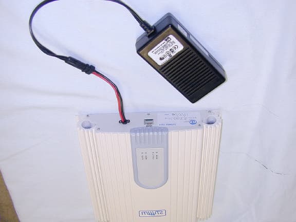
Click to zoom
Application Details
- Equipment Class
- AMP - Amplifier
- Date of Grant
- Oct 15, 2001
- Application Purpose
- Original Equipment
- Date of Application
- Oct 08, 2001
- Equipment Note
- Repeater
- Frequency Range
- 869.00000000 - 894.00000000
- Company
- Withus Company, Ltd.
- Country
- South Korea
Documents & Files
Document Text
Text extracted from the exhibit documents filed with the FCC. Open a document above to read the original.
Users Manual
AMPS REPEATER AMPS REPEATER Model:WER-824A AMPS REPEATER Table of Contents 1. Product Descriptions and Construction 2. Specification 3. Installations and Operation 4. Circuit Description 5. Troubleshooting 1. Product Descriptions and Construction 1.1 Product Descriptions AMPS REPEATER This repeater (model:WER-824A) is a compact bi-directional linear amplifier for 800 MHz AMPS band. It is ideal for extending two-way voice and data communications for null areas. This unit features 80 dB gain and output IP3 level of +45 dBm. 1.2 Construction This repeater consists of the following major elements. No. Parts Quantity Maker 1 DUPLEXER FILTER 2 EXPAN Electronics (EMD0836J0881A) 2 REPEATER MODULE 1 Withus (SHF-0589, SXA-289) 3 CONTROLLER 1 Withus 4 POWER SUPPLY 1 Withus 5 Case 1 Withus 2. Specification 2.1 Frequencies Path Frequency Remarks AMPS REPEATER Forward path (BTS to phone) 869 ~ 894 MHz Reverse path (phone to BTS) 824 ~ 849 MHz 2.2 Gains Item Spec Remarks Gain Range 50 ~ 80dB Gain adjustment step 1dB / STEP Gain adjustment error ±0.7dB/STEP 2.3 Input/Output Item Spec Remarks Input Level -40dBm ~ -70dBm Max. Output +30 dBm 1dB gain compression > +32 dBm OIP3 > +42 dBm AGC Range 30 dB (1 dB step) Forward/Reverse 2.3 Noise and Spurious Emission Item Spec Remarks Noise Figure < 3.5 dB Gain=+80dB AMPS REPEATER IMD > +34 dBc 2-Tone@25dBm/tone OIP 3 > +42 dBm 2.4 Others Item Spec Remarks Input/Output Impedance 50Ω RF Connector N-TYPE (female) 2.5 Environmental Item Spec Remarks Temperature Humidity -20 ~ +35°C 10 ~ 90% RH -Output Power Variation: < ±2dB -Others: No difference Vibration Frequency : 10 ~ 55Hz Amplitude: ±0.75mm Weight 5 Kg Dimension 250(W)x53(H)x250(D)mm Voltage AC 110V ±15% 3. Installations and Operation 3.1 Installation CAUTION: This product should be installed such that a separation distance of at least 20 cm. will be maintained between the radiating element and any nearby person. The maximum antenna gain allowed is 1.6 dB. Failure to adhere to these guidelines may cause the rf exposure levels to exceed those allowed by the FCC rules. AMPS REPEATER 3.1.1 The site shall be selected for good ventilation and smooth layout of power and antenna cables. 3.1.2 The repeater shall be installed 4 inches above ceiling for its ventilation and easy installation. 3.1.3 The repeater uses 9 Volt DC power and and a AC-DC power supply is supplied for 9 Volt DC. 3.1.4 After the repeater is bolted down, the donor antenna needs to be connected to donor antenna port of the repeater and the service antenna to be connected to the service antenna port. 3.1.5 Calculate the signal strength at the donor antenna - Rx signal strength at donor antenna feeder cable shall be calculated (Free space loss = 32.2 + 20*log(Distance in [m]) + 20*log(Frequency ) - Gain(donor antenna) + feeder loss - Actual signal strength at the donor feeder cable needs to be measured with a spectrum analyzer. - The previous two values needs to be compared and re-position the donor antenna in case the actual signal strength is lower than the pre-calculated signal strength 3.1.6 Gain shall be adjusted for proper output signal strength. Please see an example below for down link adjustment. Up link gain adjustment shall be 2 dB lower than the down link gain. (Example) Input signal -60 dBm Desired output signal +20 dBm Gain 80 dB 3.1.7 After the gain is adjusted, it needs to be checked for any alarm presence on repeater’s status LEDs. 3.1.8 ALC setting needs to be checked for proper operation. 3.2 Operations 3.2.1. Operations NMS PORT(D-SUB 9 PIN) should be connected to a serial port of a PC. AMPS REPEATER MONITOR Screen Display and Function RSSI: Up/Down Link Signal Strength RF POWER: Output Power at Donor/Service Port GAIN: Forward/Reverse Path Gain ALC *: Automatic Limiting Circuit AGC: Automatic Gain Control * Output automatically shuts off until the output power level is below +30 dBm. 4. Circuit Description 4.1 Description of major parts 4.1.1 DUPLEXER FILTER AMPS REPEATER Duplex Filter isolates transmit frequency from receive frequency as a band pass filter in both directions. So the down link signal is fed in to LNA, while up link signal is fed in to transmit terminal. DUPLEXER Specs Item Spec Remarks Frequency 869 ~ 894 MHz / 824 ~ 849 MHz Insertion Loss < 2.0 dB Return Loss > 20 dB Passband Ripple +-1.0 dB AMPS REPEATER Rx/Tx Isolation > 60 dB 3 –dB Bandwidth 25MHz Input/Output Impedance 50Ω 4.1.2 Repeater Module This is the first stage amplifier and has the greatest effect on the Repeater’s Noise Figure. The signal received from the Donor antenna is fed in to the LNA via a duplex filter. This LNA is working for 800 MHz signal with very low noise and high gain. 4.1.3 Controller AMPS REPEATER This module controls repeater’s whole functions. There are several I/O ports for measurement and monitoring of the repeater status. 4.1.4 Power Supply It supplies 8 VDC to the Repeater from the external power source (110 V AC) 4.1.2 REPEATER MODULE: LNA part This is the pre-amplifier section that has the greatest influence on the noise figure of the repeater. The signal received by the antenna passes thru the duplexer filter, and only the signal with frequency band of interest passes thru the duplexer filter. The output of the duplex filter then is fed into the LNA. This LNA is composed of low-noise and high-output circuitry that has a high gain. LNA Specifications Item Specifications Comment Frequency range 869 ~ 894 MHz / 824 ~ 849 MHz Gain 30 dB Gain flatness ±0.5 dB Noise figure < 1 dB IP3 37 dBm (Type) Input impedance 50Ω Supply voltage 6V Supply current < 150mA The high frequency signal input at J1 passes via the dc-blocking capacitor [C65] and the input impedance matching inductor [L2] and enters the low-noise amplification section [Q3 (ATF-10136)] and gets amplified by approximately 15dB with 0.8dB noise figure. The negative voltage bias of this section is comprised of active bias circuitry that senses drain current using Q4. The …
Text truncated - open the document above for the full version.
Block Diagram
1234567 7 654321 D C B A DUPLEXER B/W25M LNA DONOR ANT 824-849(869-894)MHz CONTROLLER UNIT output power,gain, a l a SGA-6489 BALANCED AMPLIFEFIER BPF 25MHz NGA-489 ATTENUATOR sxa-289 LEVEL DETCET. ¿Âμμº ̧»ó BLOCK DIAGRAM POWER SUPPLY 8V@3A AC ADAPTOR BPF 25MHz BPF 25MHz BPF 25MHz SGA-6489 BPF 25MHz »óμ¿
Cover Letter(s)
REQUEST FOR CONFIDENTIALITY Withus Co., Ltd. would like to request confidentiality with regard to the following documents in the filing for equipment approval identified by FCC ID. No. PSBWER-824A (1) Schematic diagrams contained in electronic file identified as Schematics.pdf. It is the opinion of Withus Co., Ltd that disclosure of this information would result in significant loss of revenue. This information should be kept confidential for 2 years. Authorized signature _________________________________ Printed name E. J. Jung Company name Withus Co., Ltd Company Address Migeumpark 2F, 150 Geumgok-dong,Bundang-gu, Seongnam-si, Kyongki-do, 463-830 Korea TEL:82-31-710-1841 / FAX:82-31-715-8838 Only information that is not accessible to the general public may be held confidential. Generally internal and external photos cannot be held confidential. The exception would be if the PC board is polled.
Operational Description
Operational Description This repeater (model:WUR-880) is a compact bi-directional linear amplifier for 800 MHz AMPS band. It is ideal for extending two-way voice and data communications for null areas. This unit features 80 dB gain and output IP3 level of +45 dBm. Useable output power is +30 dBm maximum. Repeater Module This is the first stage amplifier and has the greatest effect on the Repeater’ s Noise Figure. The signal received from the Donor antenna is fed in to the LNA via a duplex filter. This LNA is working for 800 MHz signal with very low noise and high gain. Controller This module controls repeater’ s whole functions. There are several I/O ports for measurement and monitoring of the repeater status. Power Supply It supplies 8 VDC to the Repeater from the external power source (110 V AC) LNA part This is the pre-amplifier section that has the greatest influence on the noise figure of the repeater. The signal received by the antenna passes thru the duplexer filter, and only the signal with frequency band of interest passes thru the duplexer filter. The output of the duplex filter then is fed into the LNA. This LNA is composed of low-noise and high-output circuitry that has a high gain.
Parts List/Tune Up Info
Tune-up Procedure As this device uses high frequency signal and components, careless adjustments of variable components result in degradation in system performance. Therefore, all repairs and adjustments must be carried out with appropriate measurement instruments. Initially check the device’s status while the malfunctioning module is still in the field. When the problem is identified, replace the malfunctioning module with an identical module. The actual repairs of individual components inside the malfunctioning module should be done at the factory.
RF Exposure Info
Prediction of MPE limit at a given distance Equation from page 18 of OET Bulletin 65, Edition 97-01 where:S = power density P = power input to the antenna G = power gain of the antenna in the direction of interest relative to an isotropic radiator R = distance to the center of radiation of the antenna Maximum peak output power at antenna input terminal:30.00(dBm) Maximum peak output power at antenna input terminal:1000(mW) Antenna gain(typical):1.6(dBi) Maximum antenna gain:1.445439771(numeric) Prediction distance:20(cm) Prediction frequency:894(MHz) MPE limit for uncontrolled exposure at prediction frequency:0.533333333(mW/cm^2) Power density at prediction frequency:0.287561(mW/cm^2) Maximum allowable antenna gain:4.282685833(dBi) 2 4R PG S π = This device is intended for use with antennas mounted on permanent outdoor structures. A separation distance of 20 cm. can reasonably be maintained. The following statement appears in the User Installation guide: CAUTION: This product should be installed such that a separation distance of at least 20 cm. will be maintained between the radiating element and any nearby person. The maximum antenna gain allowed is 1.6 dBi. Failure to adhere to these guidelines may cause the rf exposure levels to exceed those allowed by the FCC rules.
Test Report
Nemko Test Report: 1L0084RUS1 Applicant: Withus Co., Ltd. 2F Miguempark B/D 150 Geumgok-dong, Bundang-gu, Seongnam-si, Kyongki-do, Republic of Korea Equipment Under Test: WER 824A AMPS REPEATER (E.U.T.) In Accordance With: FCC Part 22, Subpart H Cellular Band Repeaters Tested By: Nemko Dallas Inc. 802 N. Kealy Lewisville, TX 75057-3136 Authorized By: Tom Tidwell, RF Group Manager Date: 7/6/01 Total Number of Pages: 74 Nemko Dallas FCC PART 22, SUBPART H CELLULAR BAND REPEATERS EQUIPMENT: WER 824A AMPS Repeater PROJECT NO.: 1L0084RUS1 Page 2 of 2 Table of Contents SECTION 1. SUMMARY OF TEST RESULTS........................................................................................................3 SECTION 2. GENERAL EQUIPMENT SPECIFICATION...................................................................................5 SECTION 3. RF POWER OUTPUT...........................................................................................................................7 SECTION 4. OCCUPIED BANDWIDTH...................................................................................................................8 SECTION 5. SPURIOUS EMISSIONS AT ANTENNA TERMINALS.................................................................9 SECTION 6. FIELD STRENGTH OF SPURIOUS................................................................................................26 SECTION 7. FREQUENCY STABILITY................................................................................................................55 SECTION 8. TEST EQUIPMENT LIST...................................................................................................................58 ANNEX A - TEST DETAILS....................................................................................................................................59 ANNEX B - TEST DIAGRAMS................................................................................................................................68 Nemko Dallas FCC PART 22, SUBPART H CELLULAR BAND REPEATERS EQUIPMENT: WER 824A AMPS Repeater PROJECT NO.: 1L0084RUS1 Page 3 of 3 Section 1. Summary of Test Results Manufacturer: AP Research Model No.: WER 824A Serial No.: None General: All measurements are traceable to national standards. These tests were conducted on a sample of the equipment for the purpose of demonstrating compliance with FCC Part 22, Subpart H. New Submission Production Unit Class II Permissive Change Pre-Production Unit THIS TEST REPORT RELATES ONLY TO THE ITEM(S) TESTED. THE FOLLOWING DEVIATIONS FROM, ADDITIONS TO, OR EXCLUSIONS FROM THE TEST SPECIFICATIONS HAVE BEEN MADE. See “ Summary of Test Data”. NVLAP LAB CODE: 100426-0 Nemko Dallas Inc. authorizes the above named company to reproduce this report provided it is reproduced in its entirety and for use by the company’s employees only. Any use which a third party makes of this report, or any reliance on or decisions to be made based on it, are the responsibility of such third parties. Nemko Dallas Inc. accepts no responsibility for damages, if any, suffered by any third party as a result of decisions made or actions based on this report. This report applies only to the items tested. Nemko Dallas FCC PART 22, SUBPART H CELLULAR BAND REPEATERS EQUIPMENT: WER 824A AMPS Repeater PROJECT NO.: 1L0084RUS1 Page 4 of 4 Summary Of Test Data NAME OF TEST PARA. NO. SPEC. MEAS. RESULT RF Power Output 22.913(a) 500W ERP < 500 W ERP Complies Occupied Bandwidth (Voice & SAT) 22.917(c) Mask Plots Complies Occupies Bandwidth (Wideband Data) 22.917(d) Mask Plots Complies Occupied Bandwidth (ST) 22.917(d) Mask Plots Complies Occupied Bandwidth (Digital) None None Plots Complies Spurious Emissions at Antenna Terminals 22.917 -13 dBm < -13 dBm Complies Field Strength of Spurious Emissions 22.917 -13 dBm E.I.R.P. < -13 dBm EIRP Complies Frequency Stability 22.355 1.5 ppm N/A N/A Footnotes: Measurement uncertainty for each test configuration is expressed to 95% probability. . Nemko Dallas FCC PART 22, SUBPART H CELLULAR BAND REPEATERS EQUIPMENT: WER 824A AMPS Repeater PROJECT NO.: 1L0084RUS1 Page 5 of 5 Section 2. General Equipment Specification Supply Voltage Input: 100-240 VAC Frequency Range: Downlink: 869 – 894 MHz Frequency Range: Uplink: 824 – 849 MHz CDMA GSM NADC CDPD AMPS (F9W) (GXW) (DXW) (F9W) (F8W, F1D) Type of Modulation and Designator: Output Impedance: 50 ohms Downlink: Per Channel: 0.5 W RF Output (Rated): Total: 1.0 W Uplink: Per Channel: 0.5 W Total: 1.0 W Frequency Translation: F1-F1 F1-F2 N/A Software Duplexer Change Fullband Coverage Band Selection: Nemko Dallas FCC PART 22, SUBPART H CELLULAR BAND REPEATERS EQUIPMENT: WER 824A AMPS Repeater PROJECT NO.: 1L0084RUS1 Page 6 of 6 Description of Operation This repeater (model: WER-824) is a compact bi-directional linear amplifier for 800 MHz AMPS band. It is ideal for extending two-way voice and data communications for null areas. This unit features 80 dB gain and output IP3 level of +45 dBm. System Diagram Nemko Dallas FCC PART 22, SUBPART H CELLULAR BAND REPEATERS EQUIPMENT: WER 824A AMPS Repeater PROJECT NO.: 1L0084RUS1 Page 7 of 7 Section 3. RF Power Output NAME OF TEST: RF Power Output PARA. NO.: 2.1046 TESTED BY: David LightTom Tidwell DATE: 6/20/01 Test Results: Complies. Test Data: Modulation Type Per Channel Power Output (dBm) Composite Power Output (dBm) Uplink AMPS 26 29 (2 Chs) Downlink AMPS 24.5 27.5 (2 Chs) Uplink CDMA 29 32 (2 Chs) Downlink CDMA 27 30 (2 Chs) Uplink NADC 29 32 (2 Chs) Downlink NADC 27 30 (2 Chs) Note: The device was tested at 98 –132 VAC. Voltage input had no effect on power output. Equipment Used: 1064-1065-1029-1030 Measurement Uncertainty: +/- 0.6 dB Temperature: 22 °C Relative Humidity: 50 % Nemko Dallas FCC PART 22, SUBPART H CELLULAR BAND REPEATERS EQUIPMENT: WER 824A AMPS Repeater PROJECT NO.: 1L0084RUS1 Page 8 of 8 Section 4. Occupied Bandwidth NAME OF TEST: Occupied Bandwidth PARA. NO.: 2.1049 TESTED BY: David LightTom Tidwell…
Text truncated - open the document above for the full version.
Contact Information
Applicant
Ken Lee(Asst. Manager of Overseas Business)
Test Firm
Nemko Dallas, Inc.Michael Cantwell
Technical Specifications
| # | Rule Parts | Frequency Range | Power Output | Emission |
|---|---|---|---|---|
| 2 | 22H | 869 MHz - 894 MHz | 1.45 W | AMP |
Other Applications from Withus Company, Ltd.

PSBWLR-1900BE
Aug 20, 2002CDMA PCS Amplifier
Equipment Class
AMP - Amplifier
PSBWLR-1900
Jan 06, 2002PCS Bidirectional Amplifier
Equipment Class
AMP - Amplifier