PSL-WEN-2015Wireless LAN PC Card
W-Link Systems Inc.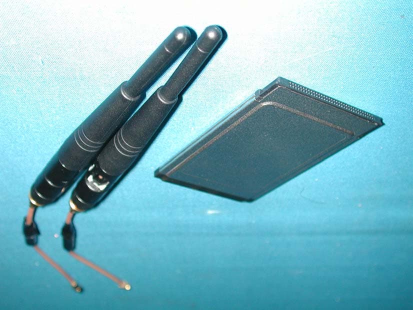
Click to zoom
Application Details
- Equipment Class
- DSS - Part 15 Spread Spectrum Transmitter
- Date of Grant
- Feb 04, 2002
- Application Purpose
- Original Equipment
- Date of Application
- Feb 04, 2002
- Equipment Note
- Wireless LAN PC Card
- Frequency Range
- 2412.00000000 - 2462.00000000
- Company
- W-Link Systems Inc.
- Country
- Taiwan
Documents & Files
Document Text
Text extracted from the exhibit documents filed with the FCC. Open a document above to read the original.
Users Manual
-1- D-Link DW-655C Wireless LAN PC Card User’s Guide CAUTION: Any changes or modifications not expressly approved by the grantee of this device could void the user's authority to operate the equipment. Introduction This User Guide is to guide you to install a Wireless LAN designed for both large and small business and SOHO environments and let you share a local printer and files, access internet, and roam about different working places. The attached drivers and utilities support for Windows 95 (OSR2), Windows 98, and Windows 2000, NT4.0 and Windows Millennium. Package Contents y D-Link DW-655C Wireless LAN PC Card y D-Link Wireless LAN CD-ROM with drivers and utilities y User’s Guide y Quick Start Guide y Warranty Card Planning your Wireless LAN There are two usage modes for Wireless LAN, Ad-hoc mode and Infrastructure mode. Please review your need and build your Wireless LAN. Ad-hoc Networking Ad-hoc network also is called Peer-to-Peer network. Without Access Point, notebook users with D-Link DW-655C Wireless LAN PC card can build Ad-hoc Peer-to-Peer wireless networks to share files with each other, share a public office printer and other peripheral resources, even access the Internet via a modem. Infrastructure Networking 802.11b-compatible Access Point is a bridge or routers connecting to the wired Ethernet network and wireless network. Through the deployment of Access Point, wireless LAN can be extended to the reach of a wired network. Therefore, a notebook user with D-Link DW-655C Wireless LAN PC Card can access to fixed local network resources. - 2 - Installation Installation for Windows 95, Windows 98 and Windows 2000 Before installing the driver, you will need a copy of the operating system installation media, usually a CD supplied with your computer or operating system. On Windows 98 systems, the installation files are sometimes archived on the hard disk in C:\WINDOWS\OPTIONS\CABS. On Windows 2000 systems, the system may prompt you to load operating system files from the Windows 2000 installation disk. Installation under Windows 95 is identical to the procedure given above for Windows 98 and Windows 2000. Only Windows 95 OSR2 or higher is supported. The Setup program also installs Configuration Utility in the DW-655C Wireless LAN PC Card in the Program directory. This configuration utility can help you to understand and maintain your Wireless LAN. Install Driver Step 1: Turn on your computer. Step 2: Insert the D-Link DW-655C Wireless LAN PC Card into the PC Card slot. Align the card properly before putting it in the slot. Insert the card firmly without forcing until it seats snugly. CAUTION: Forcing a misaligned card into the slot can damage the computer or the card. Step 3: Windows finds a new hardware shown DLINK-DW655C and asks for the driver of DW-655C Wireless PC Card. The driver installation wizard guides you through the steps standard for your operating system. Step 4: You will be asked to supply CDs or directory path information for the driver. This driver shall be located in the following directory. D:\DW655C\ (if D:\ is your CD-ROM drive) Step 5: Windows finds the driver described as D-Link DW-655C Wireless LAN PC Card. Follow the directions of Windows dialog boxes to complete the driver installation. After completing the installation, Windows dialog will display Systems Setting Change and ask to restart the notebook. Click “Yes” to reboot the computer. - 3 - Install Configuration Utility 1. Restart the computer and ensure D-Link Wireless LAN Configuration Utility CD in the CD-ROM drive. You can run the program manually by selecting Run from the Start menu and running SETUP.EXE from the CD-ROM drive. D:\DW655C\SETUP.EXE (if D:\ is your CD-ROM drive) 2. On the D-Link DW-655C Wireless LAN PC Card – Installation screen, click next to start software installation. Read the information in the Welcome dialog box and click “Next”. Then, click “Yes” if you accept the Software License Agreement. 3. Enter the name of the Wireless LAN Service Set of the wireless network (SSID) to which your computer will connect. The name you enter here must match exactly the name assigned to the access point. Characters, capitalization, and spacing must be identical. NOTE: If the access point you wish to associate with has encryption active, you must also enable encryption on the wireless client. Click Encryption in the Configuration Utilities after reboot to go to screens where you can enable and configure encryption. You must set the wireless client for the same Encryption algorithm and Key values as the access point it will associate. Refer to the Advanced Configuration section for more details about configuring encryption 4. Select which network mode is suitable for your Wireless LAN. Infrastructure Mode is default selection. This setting can be changed at any time after installation completion. 5. Accept the default program folder or select where the SETUP.exe stores the Configuration Utility. 6. Select ““Yes”, I want to restart my computer now”. Reboot your computer by clicking Finish. Operation Orienting the Antenna The PC Card antenna is attached to the end of the PC Card. For best use of the antenna: z Keep the area around the antenna clear from materials that could block or obstruct - 4 - radio transmission, such as metal objects, electronic devices, cordless telephones, and microwave oven. z If necessary, move your notebook computer a few inches to find a better signal. Environmental condition varies with users’ location, a difference of one or two inches can mean the difference between a strong and a weak signal. Even a slight change in PC orientation can improve a wireless connection. z If you have installed the Configuration Utility, you may use the Signal Strength display in the Link Info to determine the best location and orientation for a wireless network connection. LED Indication The yellow LED of Wireless LAN PC Card performs identical functions when indicating the operationa…
Text truncated - open the document above for the full version.
Block Diagram
WEN-2015 Block Diagram SW LPF SW Power Am p BPF U1 1 RF/IF CONV . XT A L OSC SA W Filter U10 ANT S W FL6 2. 4GHz BPF MMCX MMCX BPF U9 QUAD IF CONV . U 4 MAC+ Base Band Processor P1 PCMCIA Interf ace VCO VCO U18 RE G 3. 3V U19 RE G 2. 8V U15 RE G 2. 8V U7 REG 3. 3V FL4 2. 4GHz BPF FL5 2. 4GHz BPF U1 SRAM U17 FLASH U14 RF 2. 4 G H z VCO U13 IF 748M Hz VCO FL 1 374M Hz SA W Filte r X1 32KHz BPF U6 44MHz XT A L J 1 J 2 U8 T/ R S W FL3 2. 4GHz LPF U12 2. 4GHz Am p
External Photos
Report No.: 01CH021FI Page : 1 of 3 Version:1.0 Attachment 2 : EUT Detailed Photographs (1) EUT Photo (2) EUT Photo
ID Label/Location Info
W Link TM FCC ID.: PSL-WEN-2015 1F, No. 20, Park Ave. II, Science-Based Induatrial Park, HsinChu, Taiwan, R.O.C. Tel: 886 3 563-9168 Fax: 886 3 563-9198 ID & DoC Label The FCC ID and DoC Label will be placed on the equipment as shown in the photograph below. Wireless LAN PC Card W-Link Model No.: WEN-2015 TESTED TO COMPLY WITH FCC STANDARDS FOR HOME OR OFFICE USE S/N: Made in Taiwan Wireless LAN PC Card Model No.: WEN-2015 F F C C C C I I D D : : P P S S L L - - W W E E N N - - 2 2 0 0 1 1 5 5 This device complies with Part 15 of the FCC Rules. Operation is subject to the following two conditions: (1) this device may not cause harmful interference and (2) this device must accept any interference received, including interference that may cause undesired operation. S/N: Made in Taiwan
Internal Photos
Report No.: 01CH021FI Page : 2 of 3 Version:1.0 (3) EUT Photo (4) EUT Photo Report No.: 01CH021FI Page : 3 of 3 Version:1.0 (5) EUT Photo (6) EUT Photo
Operational Description
Report No. 01CH021FI Page : 5 of 46 Version:1.0 1. GENERAL INFORMATION 1.1. EUT Description Product Name : Wireless LAN PC Card Trade Name : W-Link FCC ID. : PSL-WEN-2015 Model No. : WEN-2015, DW-655C Frequency Range : 2412MHz to 2462MHz Channel Number : 11 Frequency of Each Channel (Working Frequency) : Channel 01: 2412MHz Channel 02: 2417 MHz Channel 03: 2422 MHz Channel 04: 2427MHz Channel 05: 2432MHz Channel 06: 2437MHz Channel 07: 2442MHz Channel 08: 2447MHz Channel 09: 2452MHz Channel 10: 2457MHz Channel 11: 2462MHz Type of Modulation : Direct Sequence Spread Spectrum Selection of Operating Frequency : Auto Antenna type : External dipole diversity antennas Note: 1. This device is a 2.4GHz Wireless LAN PC Card interface included a 2.4GHz receiving function, a 2.4GHz transmitting function. 2.These tests were conducted on a sample of the equipment for the purpose of Demonstrating compliance with Part 15 Subpart C Paragraph 15.247 for spread spectrum devices. 3. Regards to the different trade name. The model number were shown in the table following: Model Number Trade Mark WEN-2015 W-Link DW-655C D-Link 4.This device is a composite device in accordance with Part 15 regulations. The function receiving was measured and made a test report that the report number is 01CH021F under Declaration of Conformity. 1.2. Operation Description The EUT is Wireless LAN PC Card. Four kind of transmission speed 1,2,5.5 and 11Mbps were provide by this RF module. The modulation of RF carrier are DQPSK, DBPSK and CCK. A extender was used during the test to prove the PCMCIA card can pass all the regulation alone Self-shielding and on board power regulator were built in the EUT. Direct sequence spread spectrum modulation was adopted by this module. External dipole diversity antennas provide diversity function to improve the receiving function of module. Data can be transmitted by the radio signal connect to Internet or local network.
Test Report
Report No. 01CH021FI Page : 1 of 46 Version:1.0 Test Report Product Name : Wireless LAN PC Card Model No. : WEN-2015, DW-655C FCC ID.: PSL-WEN-2015 Applicant : W-Link Systems Inc. Address : 1F, No. 20, Park Ave. II, Science-based industrial Park, Hsin Chu, Taiwan, R.O.C. Date of Receipt : Dec. 5, 2001 Date of Test : Dec. 14, 2001 Report No. : 01CH021FI The Test Results relate only to the samples tested. The test report shall not be reproduced except in full without the written approval of QuieTek Corporation. This report must not be used to claim product endorsement by NVLAP any agency of the U.S. Government Report No. 01CH021FI Page : 3 of 46 Version:1.0 TABLE OF CONTENTS Description Page 1. GENERAL INFORMATION .....................................................................................................5 1.1. EUT Description............................................................................................................................5 1.2. Operation Description ...................................................................................................................5 1.3. Tested System Details....................................................................................................................6 1.4. Configuration of Tested System ....................................................................................................6 1.5. EUT Exercise Software .................................................................................................................7 1.6. Test Facility ...................................................................................................................................7 2. Conducted Emission....................................................................................................................8 2.1. Test Equipment List.......................................................................................................................8 2.2. Test Setup ......................................................................................................................................8 2.3. Limits ............................................................................................................................................8 2.4. Test Procedure ...............................................................................................................................9 2.5. Test Result of Conducted Emission.............................................................................................10 3. Peak Power Output ................................................................................................................... 11 3.1. Test Equipment............................................................................................................................11 3.2. Test Setup ....................................................................................................................................11 3.3. Test Condition .............................................................................................................................11 3.4. Minimum Standard......................................................................................................................11 3.5. Test Result of Peak Power Output...............................................................................................12 4. RF Exposure Evaluation ...........................................................................................................13 4.1. Friis Formula ...............................................................................................................................13 4.2. EUT Operation condition ............................................................................................................13 4.3. Test Result of RF Exposure Evaluation.......................................................................................14 5. Radiated Emission .....................................................................................................................15 5.1. Test Equipment............................................................................................................................15 5.2. Test Setup ....................................................................................................................................15 5.3. Test Condition .............................................................................................................................16 5.4. Limits ..........................................................................................................................................16 5.5. Test Procedure .............................................................................................................................17 5.6. Test Result of Radiated Emission................................................................................................18 5.7. Test Result of Band Edge ............................................................................................................30 6. Occupied Bandwidth .................................................................................................................34 6.1. Test Equipment............................................................................................................................34 6.2. Test Setup ....................................................................................................................................34 6.3. Test Condition .............................................................................................................................34 6.4. Standard Reqirement ...................................................................................................................34 6.5. Test Result of Occupied Bandwidth ........................................................................................…
Text truncated - open the document above for the full version.
Test Setup Photos
Report No.: 01CH021FI Page : 1 of 3 Version:1.0 Attachment 1: EUT Test Setup Photographs Front View of Conducted Test Back View of Conducted Test Report No.: 01CH021FI Page : 2 of 3 Version:1.0 Front View of Radiated Test Back View of Radiated Test Report No.: 01CH021FI Page : 3 of 3 Version:1.0 Front View of Radiated Test (Horn)
Contact Information
Applicant
Ms. Tan Shu(Manager)
Test Firm
DEKRA Testing and Certification Co., Ltd.Sky Hsu
Technical Specifications
| # | Rule Parts | Frequency Range | Power Output |
|---|---|---|---|
| 1 | 15C | 2.41 GHz - 2.46 GHz | 48.50 mW |
Other Applications from W-Link Systems Inc.
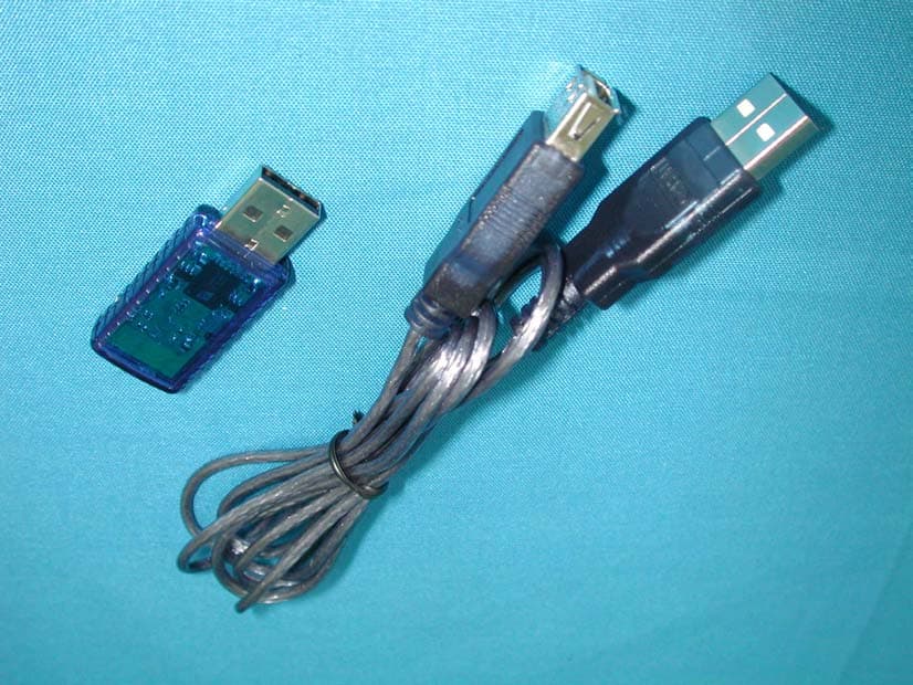
PSL-WBT-3022
Oct 31, 2002WLAN Bridge / A.P.
Equipment Class
DSS - Part 15 Spread Spectrum Transmitter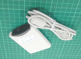
PSL-WEN-2072
Sep 12, 2002Wireless USB Adapter
Equipment Class
DSS - Part 15 Spread Spectrum Transmitter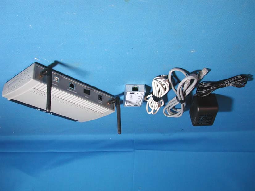
PSL-WOP-9030
May 02, 200211Mbps Wireless Bridge
Equipment Class
DTS - Digital Transmission System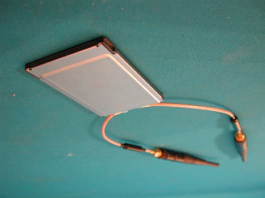
PSL-WEN-2012
Sep 10, 2001Wireless LAN PC Card
Equipment Class
DSS - Part 15 Spread Spectrum Transmitter