PTB50074Traffic Safety Light Control
Trafcon Industries, Inc.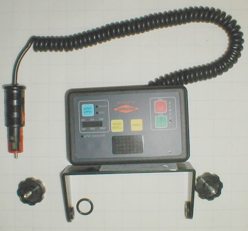
Click to zoom
Application Details
- Equipment Class
- DXX - Part 15 Low Power Communication Device Transmitter
- Date of Grant
- Jul 21, 2003
- Application Purpose
- Original Equipment
- Date of Application
- Jul 21, 2003
- Equipment Note
- Traffic Safety Light Control
- Frequency Range
- 914.00000000 - 916.00000000
- Company
- Trafcon Industries, Inc.
- Country
- United States
Documents & Files
Document Text
Text extracted from the exhibit documents filed with the FCC. Open a document above to read the original.
Users Manual
SmartFlash Arrowboard Controller Installation & Operation Manual 81 Texaco Road Mechanicsburg, PA 17050 717-691-8007 717-697-0813 FAX www.trafcon.com Revised: March, 2003 The Basics There are two variations of the SmartFlash controller. Vehicle mounted units consist of two parts, the remote control head, which includes a keypad mounted within a black enclosure and is equipped with a mounting bracket. The second part, the controller, is a plain black box, with mounting ears, and equipped with four receptacles. The controller also houses most of the electronics. Trailer mounted units consist of a controller unit with the keypad mounted within. Main Features Features common to both controllers include the following: • Solid state circuitry • Short circuit protected output circuitry • Polarity protected circuitry • Keypad operation with back lighting • Ability to “hot-swap” controls and plugs • Intensity and battery monitoring • Automatic dimming • Manual dimming (special option) • Automatic raise/lower operation (optional) • Support for electric and hydraulic actuators • Low battery warning (LED display alternates between mode and “LB”) • Audible confirmation of keyboard operation • Text and graphic markings 1 Operating Instructions Controller Layout The “On and Off” Buttons The ON and OFF buttons work as expected, when the Arrowboard is turned off the main positive (common) feed to the Arrowboard is turned off and the current draw of the system is about 10mA. There is also a power LED that is on when the Arrowboard is turned on. Lamp Sequence Control Buttons The “Select Mode” button is used to scroll through the selectable sequences. Each time this button is pressed the LED display on the controller or remote will scroll to the next sequence. When in this mode the display will flash rapidly. 2 The “Enter” button is used to set the “new” sequence as the displayed sequence. Once this button has been pressed the sequence on the Arrowboard will change to the ‘new’ sequence. Other Buttons “Toggle Display” button. This button is used to change the “bulb brightness and battery level display” between its two modes. Each time it is pressed it toggles to the other mode. Bulb brightness and Battery level Display. This display gives accurate readings of both bulb brightness and battery voltage levels. MODE 1 Bulb Brightness. This mode displays the level of brightness that the bulbs on the Arrowboard are illuminated too. The scale is from 10% to 100% and is marked above the display. MODE 2 Battery Voltage. This mode displays the voltage level of the power source. The scale is from 10 to 14 volts and is displayed underneath the display. The two readings are displayed independently; the operator can alternate between the two by pressing the “Toggle display” button. The current mode of the display is shown by the display indication LEDs; these are located to the right of the “Toggle Display” button. 3 Function Buttons (Optional) • Auto/manual dimming control: Holding both the “brightness down” and “brightness up” optional buttons down for approximately five seconds results in a change from auto to manual dimming, or vice versa. This procedure will not work when in “battery level” mode, or if the optional buttons have not been configured. Option Stickers “Lamp Brightness UP” button: Used to proceed upwards through the brightness options 1-10, and Auto. “Lamp Brightness DOWN” button: Used to proceed downwards through the brightness options 1-10, and Auto. “Sign UP” button: Used to move the Arrowboard into the up position. “Sign Down” button: Used to move the Arrowboard into the down position. 4 Display Features The “Arrowboard Sequence Display” is the main display on the controller. The primary purpose of this display is to show a flashing sequence that is identical to that on the arrowboard, this is the “real” sequence. Once the “Select Mode” button has been pressed the flashing “real” sequence disappears and a “new” sequence will appear on the display, this sequence flashes at twice the rate of the “real” sequence. Once a “new” sequence is shown on the display it will remain there until one of the following occurs: 1) The “Select Mode” button is pressed again, in this case the “new” sequence will scroll to the next “new” sequence 2) The “Enter” button is pressed, in this case the controller sends a change sequence request to the “arrowboard driver” which then changes the sequence, which is displayed on the arrowboard. At this point the “new” sequence on the controller display will begin to flash slower and become the “real” sequence. If no buttons are pressed for a time period of 5 seconds the “new” sequence will disappear and the “real” sequence will be displayed The “Auto Dimming” LED: This is located just above the “Bulb brightness and battery level” display. Its purpose is to alert the operator when the Arrowboard is set in auto-dimming mode. The “Sign Up” LED: This is located above option button four. It is on when the Arrowboard is in the UP position. 5 20 Way D-3100 Plug TOP Smart Flash MB Series Controller 10 Way D-3100 Plug (2) 4 Way D-5200 Plug Smart Flash MB Series Remote 10 Way D-3100 Plu g (2) 4 Way D-5200 Plug 0 Way D-3100 Smart Flash TC Series Controller 6 7 Controller D-3100 Plug Wiring Circuit Wire Color Gauge 1 Red 16 2 Red 18 3 White 18 4 White/Red 22 5 Option 6 NC 7 Black 18 8 Green 18 9 White/Green 22 10 Option Remote Cable 4 Way Plug Wiring Circuit Wire Color Gauge 1 Red 18 2 Black 18 3 White 18 4 Green 18 NOTE: Use only shielded cable. 8 Top Plug Pin Wire Color Gauge Function 1 Green/Yellow or White 16 16 Actuator – Positive 2 Black/Yellow or Black 16 16 Actuator - Negative 3 Red 14 Power – Positive 4 Orange 14 Common to Lamps Bottom Plug Pin Wire Color Gauge Function 1 Black 14 Ground - Negative 2 Black 14 Ground - Negative 3 Red 14 Power - Positive 4 Orange 14 Common to Lamps 9 10 Lamp Wiring Circuits Circuit Wire Color Gauge Function Application 1 Brown 18 Lamp circuit All 2 Red …
Text truncated - open the document above for the full version.
Cover Letter(s)
nRF903 Single Chip RF Transceiver Information
Cover Letter(s)
INC. 81 TEXACO ROAD MECHANICSBURG, PA 17055-2623 (717) 691-8007 Letter of Agency August 7, 2001 American Telecommunications Certification Body, Inc. 6731 Whit tier Avenue Suite C110 McLean, V A 2210 1 To Whom It May Concern: Please be advised that Trafcon Industries, Inc. authorizes Washington Laboratories, Ltd. to act on our behalf, until otherwise notified, for applications submitted to American Telecommunications Certification Body, Inc. (ATCB). We certify that we are not subject to denial of federal benefits, that includes FCC benefits, pursuant to Section 5301 of the Anti-Drug Abuse ACT of 1988, U.S.C. 862. Further, no party, as defined in 47 CFR 1.2002(b), to the application is subject to denial of federal benefits, that includes FCC benefits. Thank you for your attention to this matter . Sincerely, ~~~ Kevin Miller Technical Services
Cover Letter(s)
INC. 81 TEXACO ROAD MECHANICSBURG, PA 17055-2623 (717) 691-8007 Request for Confidentiality August 7, 2001 American Telecommunications Certification Body, Inc. 6731 Whit tier Avenue Suite C110 McL.ean, V A 22101 Certification Application PTBSOO69 RE: Fccm: Please be advised that the following exhibits are to be held confidential on behalf of Trafcon Industries; Inc: Technical Descriptions . Schematics . Block Diagrams . The application contains technical information that Trafcon Industries, Inc. deems to be trade secrets and proprietary. If made public, the information might be used to the disadvantage of the applicant in the market p1ace. Thank you for your attention to this matter . Sincerely, ~~ Kevin Miller Technical Services
External Photos
Overall View Front Panel Back Panel Top / Antenna Side Bottom
External Photos
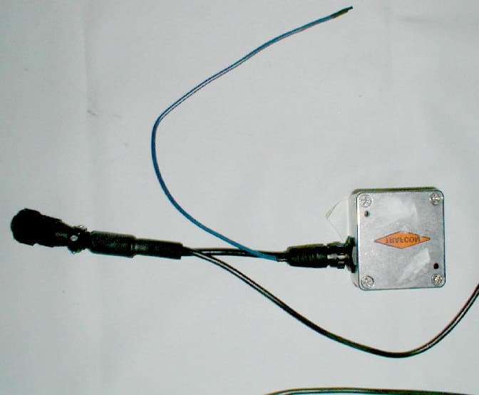
Overall View Front Panel Back Panel / Bottom Back Panel / Top Side
ID Label/Location Info
Material: Aluminum Foil with Permanent Adhesive; Mylar Overlay FCC Label Location Model: 50074 FCC ID: PTB50074 This device complies with Part 15 of the FCC Rules. Operation is subject to the following two conditions: (1) this device may not cause harmful interference, and (2) this device must accept any interference received, including interference that may cause undesired operation. TRAFCON
ID Label/Location Info
Material: Aluminum Foil with Permanent Adhesive; Mylar Overlay FCC Label Location Model: 50074 FCC ID: PTB50074 This device complies with Part 15 of the FCC Rules. Operation is subject to the following two conditions: (1) this device may not cause harmful interference, and (2) this device must accept any interference received, including interference that may cause undesired operation. TRAFCON
Internal Photos
Link Cover Open Link Radio Board Top Link Radio Board Bottom
Internal Photos
Remote Cover Open Remote Radio Board Top Remote Radio Board Bottom
Test Report
Document 7511-01, Rev. 0 FCC ID: PTB50074 FCC Certification Test Report Washington Laboratories, Ltd July 2003 FCC Certification Test Report for Trafcon Industries, Inc. FCC ID: PTB50074 July 15, 2003 Prepared for: Trafcon Industries, Inc. 81 Texaco Road Mechanicsburg, PA 17055-2623 Prepared By: Washington Laboratories, Ltd. 7560 Lindbergh Drive Gaithersburg, Maryland 20879 FCC Certification Test Report Document 7511-01, Rev. 0 FCC ID: PTB50074 FCC Certification Test Report Washington Laboratories, Ltd July 2003 FCC Certification Test Program FCC Certification Test Report for the Trafcon Industries, Inc. SmartFlash FCC ID: PTB50074 July 15, 2003 WLL JOB# 7511 Prepared by: Brian J. Dettling Documentation Specialist Reviewed by: Michael Violette President Document 7511-01, Rev. 0 FCC ID: PTB50074 FCC Certification Test Report Washington Laboratories, Ltd July 2003 ii Abstract This report has been prepared on behalf of Trafcon Industries, Inc. to support the attached Application for Equipment Authorization. The test report and application are submitted for a Periodic Intentional Radiator under Part 15.249 of the FCC Rules and Regulations. This Federal Communication Commission (FCC) Certification Test Report documents the test configuration and test results for a Trafcon Industries, Inc. SmartFlash Wireless Remote and Wireless Link. Testing was performed on an Open Area Test Site (OATS) of Washington Laboratories, Ltd, 7560 Lindbergh Drive, Gaithersburg, MD 20879. Site description and site attenuation data have been placed on file with the FCC's Sampling and Measurements Branch at the FCC laboratory in Columbia, MD. Washington Laboratories, Ltd. has been accepted by the FCC and approved by NIST NVLAP (NVLAP Lab Code: 200066-0) as an independent FCC test laboratory. The Trafcon Industries, Inc. SmartFlash Wireless Remote and Wireless Link comply with the limits for a Periodic Intentional Radiator device under Part 15.249 of the FCC Rules and Regulations. Document 7511-01, Rev. 0 FCC ID: PTB50074 FCC Certification Test Report Washington Laboratories, Ltd July 2003 iii Table of Contents Abstract......................................................................................................ii 1 Introduction...................................................................................................................1 1.1 Compliance Statement............................................................................................1 1.2 Test Scope............................................................................................................1 1.3 Contract Information..............................................................................................1 1.4 Test Dates.............................................................................................................1 1.5 Test and Support Personnel....................................................................................1 1.6 Abbreviations.........................................................................................................2 2 Equipment Under Test....................................................................................................3 2.1 EUT Identification & Description............................................................................3 2.2 Test Configuration..................................................................................................4 2.3 Testing Algorithm...................................................................................................4 2.4 Test Location.........................................................................................................4 2.5 Measurements........................................................................................................5 2.5.1 References.....................................................................................................5 2.6 Measurement Uncertainty.......................................................................................5 3 Test Equipment..............................................................................................................6 4 Test Results...................................................................................................................7 4.1 Duty Cycle Correction...........................................................................................7 4.1.1 Duty Cycle Calculation: Link..........................................................................7 4.1.2 Duty Cycle Calculation: Remote...................................................................10 4.2 Occupied Bandwidth: (FCC Part §2.1049)..........................................................14 4.3 Radiated Spurious Emissions: (FCC Part §2.1053)...............................................17 4.3.1 Test Procedure..........................................................................................17 Document 7511-01, Rev. 0 FCC ID: PTB50074 FCC Certification Test Report Washington Laboratories, Ltd July 2003 iv List of Tables Table 1. Device Summary: Wireless Link..............................................................................3 Table 2. Device Summary: Wireless Remote.........................................................................4 Table 3: Test Equipment List...............................................................................................6 Table 4. Duty Cycle Correction..........................................................................................10 Table 5. Duty Cycle Correction..........................................................................................14 Table 6. Occupied Bandwidth Results................................................................................17 Table 7. Radiated Spurious Emissions Limits.......................................................................17 Table 8: Radiated Emission Test Data...................................…
Text truncated - open the document above for the full version.
Test Setup Photos
Emissions Testing – Front Emissions Testing – Back
Test Setup Photos
Emissions Testing – Front Emissions Testing – Back
Contact Information
Applicant
Kevin Miller(Manager)
Technical Contact
Washington Laboratories, Ltd.Gregory M Snyder
[email protected]301-417-0220
7560 Lindbergh Drive · Gaithersbergh, Maryland · United States
Test Firm
Washington Laboratories, Ltd.Michael Violette
Technical Specifications
| # | Rule Parts | Frequency Range | Power Output |
|---|---|---|---|
| 1 | 15C | 914 MHz - 916 MHz | - |
Other Applications from Trafcon Industries, Inc.
PTB50069
Sep 09, 2001Traffic Safety Light Control
Equipment Class
DXX - Part 15 Low Power Communication Device Transmitter