PTN00658WIRELESS CAMERA
Satow Electronic Co., LTD.Application Details
- Equipment Class
- DXX - Part 15 Low Power Communication Device Transmitter
- Date of Grant
- Dec 22, 2005
- Application Purpose
- Original Equipment
- Date of Application
- Dec 22, 2005
- Equipment Note
- WIRELESS CAMERA
- Frequency Range
- 2414.00000000 - 2468.00000000
- Company
- Satow Electronic Co., LTD.
- Country
- China
Documents & Files
Document Text
Text extracted from the exhibit documents filed with the FCC. Open a document above to read the original.
Users Manual
6B&W WIRELESS MONITOR SYSTEM " USER’S MANUAL 8251658001 User Information The users manual or instruction manual for an intentional or unin tentional radiator shall caution the user that changes or modifications not expressly approved by the party responsible for compliance could void the user’s authority to operate the equipment. For a Class B digital device or peripheral, the instructions furnished the user shall include the following or similar statemen t, placed in a prominent location in the text of the manual. The Federal Communications Commission Radio Frequency In terference Statement includes the following paragraph. This equipment has been tested and found to comply with the lim its for a Class B Digital Device, pursuant to Part 15 for the FC C Rules. These limits are designed to provide reasonable protection against harmful interference in a residential installation. This equipment generates, uses and can radi ate frequency energy and, if not installed and used in accordance with the instructi on may cause interference to radio communication. However, there is no guarantee that interference will not occur in a particular installati on. If this equipment does cause harmful interference to radio or television reception, which can be determined by turning the equi pment off and on, the user is encouraged to try to correct the interference by one or more of the following measures: --Reorient or relocate the receiving antenna. --Increase the separation between the equipment and receiver. --Connect the equipment into an outlet on a circuit from that to which the receiver is connected. --Consult the dealer or an experienced radio / TV technician for help. Keep all its pars and accessories out of young children's reach. The camera's performance can be adversely affected by fingerprints or dirt on the lens surface. Avoid touching the lens surface with your fingers. Should the lens become dirty, use a blower to blow off dirt and dust, or a soft, dry cloth to wipe off the lens. Keep dry. Precipitation, humidity, and liquids, contain minerals that will corrode electronic circuits. Do not use or store in dusty, dirty areas. Do not store in hot areas. High temperatures can shorten the life of electronic devices and warp or melt certain plastics. Do not store in very cold areas. When the system warms up (to its normal temperature), moisture can form inside the case, which may damage electronic circuit boards. Do not attempt to open the case. Non-expert handling of the device may damage the system. Avoid dropping and strong impact. Operate this product using only the power supply included with it or provided as an accessory. Do not overload electrical outlets or extension cords as this can result in fire or electric shock. Do remember that you are using public airwaves when you use the system and that sound and video may be broadcast to other 2.4 GHz receiving devices. Conversations, even from rooms near the camera, may be broadcast. To protect the privacy of your home, always turn the camera off when not in use. When you don't use this kit for a long time,please unplug the power plug on both monitor and camera. Precautions - 11 - Antenna socket on the Wall VCR VIDEO INAUDIO IN Connections 3.When receiving TV programs 4. When recording the output signal When receiving CATV or outdoor antenna signal When using telescope antenna for receiving You need pull out it and adjust its direction to obtain the best effect. - 1 - Contents Introduction.....................................................................................1 ........................ 2 ......................... 4 ...................6 ...........................................................................................7 .................................................................................. 8 ....................................................................................10 ..............................................................................12 Front Panel Components And Controls Of Monitor Rear Panel Components And Controls Of Monitor Front/rear Panel Components And Controls of camera Features Specifications Connections Troubleshooting Introduction The kit comes with a B/W wireless camera and a 6" B/W monitor, it will help you to build-up a portable, easy-to-install, cost-efficient, and expandable security system. Using the latest wireless technology, signals from the camera travel through walls and floors to the monitor. Except that, the monitor can also receive TV programs and AV signal. Especiallyits perfect motion detection function can help you to shift from TV/AV/STANDBY mode to 2.4G mode and turn on the screen automatically, at the same time it is accompanied by arioso “DingDong” sound. - 10 - VCD AC/DC adapter VIDEO OUTAUDIO OUT 1.When receiving 2.4G wireless signal Connections 2. When receiving AV wired signal Camera Or from Camera AC/DC adapter AC/DC adapter - 2 - 1 2 3 4 12 13 5 6 7 8 9 10 11 1VOLUME KNOB Adjusts the audio level. Turn this control up to increase the audio level and turn it down to reduce the audio level. 2MODE BUTTON Press this button to select working mode(2.4G/AV/TV). 3BAND BUTTON Press this button to select TV band(VL/VH/UHF). 4POWER BUTTON Press this button to turn on or turn off the machine. 5LED for 2.4G mode The red LED shows that the machine is working in 2.4G mode. 6LED for AV mode The red LED shows that the machine is working in AV mode. 7LED for TV mode The red LED shows that the machine is working in TV mode. Front Panel Components And Controls Of Monitor - 9 - CAMERA ITEM SPECIFICATION Sensor 1/4CMOS Picture Elements 514(H)484(V) PIXELS Resolution 420 TVL System CCIR/EIA Scanning Frequency CCIR H:15625Hz V:50Hz/EIA H:15734Hz V:60Hz RF Frequency CH1:2414MHz, CH2:2432MHz, Ch3:2450MHz, CH4:2468MHz RF Power 10 dBm Transmitter Distance (Open air) 100c Min lllumination 0 LUX (with IR LED) S/N Ratio 48 dB BLC Auto Electronic shutter CCIR1/25S~1.49uSEIA1/30S~1.875uS …
Text truncated - open the document above for the full version.
Block Diagram
Applicant: SATOW ELECTRONIC CO., LTD FCC ID: PTN00658
External Photos
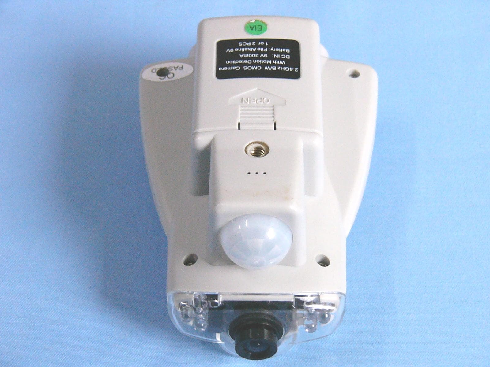
EUT EXTERIOR PHOTO Applicant: Satow Electronic Co., Ltd. FCC ID: PTN00658
ID Label/Location Info
Applicant: Satow Electronic Co., Ltd. FCC ID: PTN00658 FCC ID: PTN00658 This device complies with part 15 the FCC rules. Operation is subject to the following two condition: (1). This device may not case harmful interference, (2).This device must accept any interference received, including interference that may cause undesired operation The label must not be a stick-on paper label. The label on these products must be permanently affixed to the product and readily visible at the time of purchase and must last the expected lifetime of the equipment not be readily detachable. Proposed Label Location On EUT EUT Bottom View/Proposed FCC ID LABEL location
Operational Description
Applicant: SATOW ELECTRONIC CO., LTD FCC ID: PTN00658 1. LEE-583BAL is the B/W camera of 2.4GHz wireless transmitter system, which consists of four parts: A. MOTION DETECTOR: Consist of CMOS sensor and appendix components, IC VC0701 buit-in motion detection/trigger function, And startup power to begin working. B. POWER SUPPLY PART: Consist of IC UTC34063 and appendix components. It can provide stable power to the CMOS CAMERA and 2.4G TX MODULE when the power voltage is not stable. C. CMOS CAMERA PART: Single chip 1/4 inch format video image sensor, generates composite video signal, while additional audio-amplifying circuit diagram can amplify the weak signal from microphone. D. 2.4G MODULE PART: modulate Video, Audio l to 2.4G Band and send out. 2. The type of modulation is FM.
Schematics
583A2.sch-1 - Sat Jun 25 09:26:45 2005 583AV2.sch-1 - Sat Jun 25 09:03:58 2005
Schematics
ZT-623A_B.sch-1 - Thu Dec 22 16:46:25 2005
Test Report
FCC 47 CFR PART 15 SUBPART C TEST REPORT For SATOW ELECTRONIC CO., LTD. 6’’B/W WIRELESS MONITOR SYSTEM Model: LEE-658BTW/583BAL LEE-657BW4/593BAL LEE-658BW4/603BAL Trade Name: SATOW Prepared for SATOW ELECTRONIC CO., LTD. SATELLITE BLDG, HUADA INDUSTRIAL PARK, WEST RENMIN ROAD ZHUHAI, GUANGDONG, China Prepared by SINTEK LABORATORY CO., LTD. No. 7, XINSHIDAI INDUSTRIAL, GUANTIAN VILLAGE, SHIYAN TOWN, BAOAN DISTRICT, SHENZHEN, GUANGDONG, P.R.C. TEL: 86-755-27604866 FAX: 86-755-27608359 Note: This report shall not be reproduced except in full, without the written approval of Sintek Laboratory CO., Ltd. This document may be altered or revised by Sintek Laboratory Co., Ltd. personnel only, and shall be noted in the revision section of the document. Page 1 of27 TABLE OF CONTENTS 1. TEST RESULT CERTIFICATION.............................................................................................3 2. EUT DESCRIPTION....................................................................................................................4 3. TEST METHODOLOGY.............................................................................................................5 3.1 EUT CONFIGURATION...................................................................................................................5 3.2 EUT EXERCISE...............................................................................................................................5 3.3 GENERAL TEST PROCEDURES........................................................................................................5 3.4 FCC PART 15.205 RESTRICTED BANDS OF OPERATIONS...................................................6 3.5 DESCRIPTION OF TEST MODES......................................................................................................6 4. INSTRUMENT CALIBRATION.................................................................................................7 5. FACILITIES AND ACCREDITATIONS...................................................................................8 5.1 FACILITIES 8 5.2 EQUIPMENT...................................................................................................................................8 5.3 LABORATORY ACCREDITATIONS AND LISTING.............................................................................8 6. SETUP OF EQUIPMENT UNDER TEST..................................................................................9 6.1 SETUP CONFIGURATION OF EUT....................................................................................................9 7. FCC PART 15.247 REQUIREMENTS......................................................................................10 7.1 BAND EDGES MEASUREMENT...........................................................................................10 7.2 RADIATED EMISSIONS................................................................................................................14 7.3 POWER LINE CONDUCTED EMISSIONS.......................................................................................22 8. APPENDIX 1 PHOTOGRPHS OF TEST SETUP...................................................................25 Page 2 1. TEST RESULT CERTIFICATION Applicant: SATOW ELECTRONIC CO., LTD SATELLITE BLDG, HUADA INDUSTRIAL PARK, WEST RENMIN ROAD, ZHUHAI, GUANGDONG, CHINA Equipment Under Test: 6”B/W WIRELESS MONITOR SYSTEM Tra de Na me: SATOW Model: LEE-658BTW/583BAL, LEE-657BW4/593BAL, LEE-658BW4/603BAL Date of Test: December 14, 2005 Report No. : ST0511019 FCC ID : PTN00658 APPLICABLE STANDARDS STANDARD TEST RESULT FCC Part 15 Subpart C No non-compliance noted We hereby certify that: The above equipment was tested by SINTEK LABORATORY CO., LTD. The test data, data evaluation, test procedures, and equipment configurations shown in this report were made in accordance with the procedures given in ANSI C63.4: 2001 and the energy emitted by the sample EUT tested as described in this report is in compliance with the requirements of FCC Rules Part 15.249. The test results of this report relate only to the tested sample identified in this report. Approved by: Reviewed by: Page 3 2. EUT DESCRIPTION Product 6”B/W WIRELESS MONITOR SYSTEM Tra de Na me SATOW Model Number LEE-658BTW/583BAL, LEE-657BW4/593BAL, LEE-658BW4/603BAL Model Discrepancy N/A Power Supply DC 9V 300MA Frequency Range 2414 ~ 2468 MHz Antenna Specification The EUT’S antenna is integrated on the main PCB Number of Channels 4 Channels Note: This submittal(s) (test report) is intended for FCC ID: PTN00658 filing to comply with Section 15.247 of the FCC Part 15, Subpart C Rules. Page 4 3. TEST METHODOLOGY The tests documented in this report were performed in accordance with ANSI C63.4 and FCC CFR 47 2.1046, 2.1047, 2.1049, 2.1051, 2.1053, 2.1055, 2.1057, and 15.249. 3.1 EUT CONFIGURATION The EUT configuration for testing is installed on RF field strength measurement to meet the Commissions requirement and operating in a manner that intends to maximize its emission characteristics in a continuous normal application. 3.2 EUT EXERCISE The EUT was operated in the engineering mode to fix the TX frequency that was for the purpose of the measurements. According to its specifications, the EUT must comply with the requirements of the Section 15.249 under the FCC Rules Part 15 Subpart C. 3.3 GENERAL TEST PROCEDURES Conducted Emissions The EUT is placed on the turntable, which is 0.8 m above ground plane. According to the requirements in Section 13.1.4.1 of ANSI C63.4: 2001, Conducted emissions from the EUT measured in the frequency range between 0.15 MHz and 30MHz using CISPR Quasi-peak and average detector modes. Radiated Emissions The EUT is placed on a turn table, which is 0.8 m above ground plane. The turntable shall rotate 360 degrees to determine the position of maximum emission level. EUT is set 3m away from the receiving antenna, which varied from 1m to 4m to find out the highest emission. And also, each emi…
Text truncated - open the document above for the full version.
Test Setup Photos
TEST SETUP PHOTO Applicant: Satow Electronic Co., Ltd. FCC ID: PTN00658 CONDUCTION: Radiation:
Contact Information
Applicant
Dong Gang Wei(Material Control Manager)
Test Firm
SinTek Laboratory Co., Ltd.Eric Lin
Technical Specifications
| # | Rule Parts | Frequency Range | Power Output |
|---|---|---|---|
| 1 | 15C | 2.41 GHz - 2.47 GHz | - |
Other Applications from Satow Electronic Co., LTD.
PTN00899
Apr 05, 20042.4GHz Wireless TV & Monitor System
Equipment Class
DXX - Part 15 Low Power Communication Device Transmitter
PTN173BAL
Sep 22, 2002Video Sender
Equipment Class
DXX - Part 15 Low Power Communication Device Transmitter
PTNLEE43
Oct 03, 2001Wireless Camera
Equipment Class
DXX - Part 15 Low Power Communication Device Transmitter