PV5MSD11061989R/C Car
Meisida Electronic Toys Co., Ltd
Click to zoom
Application Details
- Equipment Class
- DXX - Part 15 Low Power Communication Device Transmitter
- Date of Grant
- Dec 21, 2011
- Application Purpose
- Original Equipment
- Date of Application
- Dec 21, 2011
- Equipment Note
- R/C Car
- Frequency Range
- 27.14500000 - 27.14500000
- Country
- China
Documents & Files
Document Text
Text extracted from the exhibit documents filed with the FCC. Open a document above to read the original.
Users Manual
1:8 SCALE R/C CAR Operation Manual (Please read this manual carefully before operation) Caution in Batteries Usage z 7.2V Rechargeable Battery Pack. z The supply terminals are not to be short-circuited. z Crust-broken batteries or leaking-out batteries are not to be used. z Do not drop the battery into water or fire or even dissolve the battery. z Make sure to inspect the wire, pin, crust and other components termly, in case any broken, stop using until repaired well. z The charger and battery are not toys. z Rechargeable batteries are only to be charged under adult supervision. z Only batteries of the same or equivalent type as recommended are to be used. z Pull the charger off the socket after finish charging. Forbid to leave the charger on the socket for a long time. z Exhausted batteries are to be removed from the toy. z Do not use any liquid to clean the toy and its accessories. z Non-rechargeable batteries are not to be recharged. z Rechargeable batteries are to be removed from the toy before charged. z Different types of batteries or new and used batteries are not to be mixed. z Batteries are to be inserted with the correct polarity. z Connect the charger and battery then plug into the socket. Charge duration is 4-6 hours. No charging is allowed after this. (First charge duration must be about 8 hours.). Caution: 1. Enhance attention when charging, keep the battery away from the flammable materials. 2. In the course of charge, it is normal that temperatures of the charger and battery will be on the rise. But in case strange odor, smoking, noises occur in the course of charging, pull the charger off the socket immediately, stop using until repaired well. Caution in Operation z Do not play outdoors when thundering. z Do not run the toy car on rainy day or wet surface, this shall lead to breakdown of the car. z Do not play the toy car near the broadcasting station or television station or together with other same frequency car so as to avoid being interfered. z The toy may has functional sharp-edges, small detachable parts which may cause potential danger to children, please operate the toy under adult supervision. z Do not plug the antenna or other exposed wire into the socket. z The toy is not intended for children under 3 yeas old. z Toy must only be used with the recommended charger. Loading & Unloading of the Battery of the Car 1. Turn “OFF” the switch. Use a screwdriver to open the battery cover. 2. Plug the fully charged 7.2V battery into the vehicle connector, put the battery inside the battery groove. 3. Fasten the battery cover with screwdriver. 4. Turn the switch “ON”. Caution: When the car switch is turned “ON”, don’t touch the wheels or insert the fingers into the gap between the wheels and vehicle to avoid any accidentally injure, the children should be paid more attention. Loading & Unloading of the Battery of Controller 1. Turn “OFF” the switch. Use a screwdriver to open the battery cover. 2. Install 2”AA”size battery after checking the positive and negative polarity. 3. Fasten the battery cover with screwdriver. Caution: Turn “ON” the switch and the indicated light on, that means the battery is installed correctly. Otherwise reinstall the battery. Analysis of Breakdowns Readjust the toy car before sending for repair, because the breakdown is largely caused by low battery. Conditions of the car Possible Reasons Ways of Inspection & Adjustment No battery in the remote controller or the car Install the battery Stop Working or Work Slowly Incorrect installation of the battery of the remote controller or the car Reinstall the battery BATTERY PACK CHARGER BATTERY PACK Batteries are only to be charged under adult supervision. ON/OFF Backward Forward Turn left Turn ri ght Horn Low battery of the remote controller Change for new battery Low battery of the car Recharge the battery Low battery of the remote controller Change for new battery Interfered by electric wave Change for new place Out of Control Same frequency car operated at the same time nearby Change for new place Maintenance: 1. Make sure to avoid any man-made broken such as car collision, grinding and staving, falling off and so on . 2. Remove the battery after playing, wipe the toy car clean (do not use any liquid) then put away under room temperature in dry place or toy cabinet. 3. Stop operating immediately in case any broken, meanwhile move the toy away from any flammable materials safely. This device complies with part 15 of the FCC Rules. Operation is subject to the following two conditions: (1) This device may not cause harmful interference, and (2) This device must accept any interference received, including interference that may cause undesired operation. Any Changes or modifications not expressly approved by the party responsible for compliance could void the user's authority to operate the equipment.
Block Diagram
CODE TRANSMISSION BLOCK DIAGRAM OF TRANSMISSION SIGNAL MODULATION ELECTRICAL DRIVE BLOCK DIAGRAM OF RECEIVING DECODE SIGNAL RECEIVED z 27.145MHz 27.145MHz 27.145MHz
External Photos
EXHIBIT B - EUT EXTERNAL PHOTOGRAPHS EUT – Front View EUT – Rear View EUT – Battery Compartment View
ID Label/Location Info
EXHIBIT A - FCC ID LABELING AND LOCATION FCC ID Label FCC ID Label Location Label here The label shown shall be permanently affixed at a conspicuous location on the device and be readily visible to the user at the time purchase (Labeling requirements per 2.925)
Internal Photos
EXHIBIT C - EUT INTERNAL PHOTOGRAPHS EUT – Cover off View EUT – Main Board Top View Antenna EUT – Main Board Bottom View EUT – Antenna View Modification Location
Operational Description
Circuit Description Battery power by R2 to IC2791T, and also power supply for Q1, Q2 . oscillation circuit is composed of Q1、C5 and crystal,port 4 of block of IC 2791T will output code signal when press button, code signal and 27.145MHz carrier are modulated by Q2, and then transmit with C3 and L1.
Schematics
1 2 3 4 56 ABCD 6 5 4 3 2 1 D CBA Titl e Number Revision Size B Date: 14-Dec-2011 Sheet of File: E:\ 电路图 \Erin.ddb Drawn By: R1330 R 360k R368K R610 R422K Q1C945 Q2C945 C1103 C347 C747 C647 C547 S1 喇叭 S2 ON/OFF F 前进 B 后退 LED L22.2uH L18.2uH ANT C2104 C 104 L 左转 R 右转 R510 R210 BT3V 45678910 11121314151617 123 IC2791T H20909T-1-27MHz Y1 27.145M L32.2uH Meisida Electronic Toys Co., Ltd 27.145 MHz 1 2 3 4 56 ABCD 6 5 4 3 2 1 D CBA Titl e Number Revision Size B Date: 14-Dec-2011 Sheet of File: E:\ 电路图 \Erin.ddb Drawn By: ANT 27.145MHz L34.7uH C910 C447 C847 Q9C1815 Y L2 6.8uH C3332 R101K R13120K C54.7uF L1 C12473 R143.9K R1556K C6104 C101uF R1810 18 27 36 45 LM3 58 C11501 R16470K R1718K R2310KR24100k C14222 C12104 R2510k R2222K C13220uF 18 27 36 45 LM386N C22104 C23104 C19103 C18100uF C17 220uF C20104 SPEAKER R22560 R2010 D4IN4001 R2710 101112131415161718 123456789 ICRS2791R R2110KR330K C104 BT7. 2V 调整 1 Vin 3 Vout 2 LM317L R191K R111.5K D3IN4001 C7104 C21470uF Q28050D Q3 S9014 Q8 8050D Q4 8050D Q18050D Q7 S9014 Q6 8550D Q5 8550D R9100 R8100 R122.2KR72.2K M1 M2 R20.25/5W R1 0.25/5W R62.2KR52.2K C247uF C147uF H20909R-27MHz J2 6V J1 6V D2 1N4148 D1 1N4148 C1310uF 前灯 LED 后灯 LED R4330 R3330 AB AB Meisida Electronic Toys Co., Ltd
Test Report
Note: This test report is prepared for the customer shown above and for the device described herein. It may not be duplicated or used in part without prior written consent from Bay Area Compliance Laboratories Corp. This report must not be used by the customer to claim product certification, approval, or endorsement by NVLAP*, or any agency of the Federal Government. * This report contains data that are not covered by the NVLAP accreditation and are marked with an asterisk “★” (Rev.2) FCC PART 15.227 MEASUREMENT AND TEST REPORT For Meisida Electronic Toys Co., Ltd. No. 99, HuiZuo Road, HaiCang Zone, Xiamen, Fujian, China FCC ID: PV5MSD11061989 Report Type: Original Report Product Name: R/C car Test Engineer: Jimmy Xiao Report Number: RSZ111205001-00 Report Date: 2011-12-19 Reviewed By: Alvin Huang EMC Engineer Test Laboratory: Bay Area Compliance Laboratories Corp. (Shenzhen) 6/F, the 3rd Phase of WanLi Industrial Building, ShiHua Road, FuTian Free Trade Zone Shenzhen, Guangdong, China Tel: +86-755-33320018 Fax: +86-755-33320008 www.baclcorp.com.cn Bay Area Compliance Laboratories Corp. (Shenzhen) Report No.: RSZ111205001-00 FCC Part 15.227 Page 2 of 15 TABLE OF CONTENTS GENERAL INFORMATION.......................................................................................................................................3 PRODUCT DESCRIPTION FOR EQUIPMENT UNDER TEST (EUT) .....................................................................................3 OBJECTIVE...................................................................................................................................................................3 RELATED SUBMITTAL(S)/GRANT(S).............................................................................................................................3 TEST METHODOLOGY..................................................................................................................................................3 TEST FACILITY.............................................................................................................................................................3 SYSTEM TEST CONFIGURATION ..........................................................................................................................5 JUSTIFICATION.............................................................................................................................................................5 EUT EXERCISE SOFTWARE..........................................................................................................................................5 SPECIAL ACCESSORIES.................................................................................................................................................5 EQUIPMENT MODIFICATIONS.......................................................................................................................................5 CONFIGURATION OF TEST SETUP.................................................................................................................................5 BLOCK DIAGRAM OF TEST SETUP................................................................................................................................6 SUMMARY OF TEST RESULTS...............................................................................................................................7 FCC §15.203 - ANTENNA REQUIREMENT.............................................................................................................8 APPLICABLE STANDARD..............................................................................................................................................8 FCC §15.205, §15.209 & §15.227 – FIELD STRENGTH AND RESTRICTED BAND EMISSIONS ...................9 STANDARD APPLICABLE..............................................................................................................................................9 MEASUREMENT UNCERTAINTY....................................................................................................................................9 EUT SETUP..................................................................................................................................................................9 EMI TEST RECEIVER SETUP.......................................................................................................................................10 TEST EQUIPMENT LIST AND DETAILS.........................................................................................................................10 CORRECTED AMPLITUDE & MARGIN CALCULATION.................................................................................................10 TEST DATA................................................................................................................................................................10 FCC §15.215(C) – 20 DB EMISSION BANDWIDTH..............................................................................................13 APPLICABLE STANDARD............................................................................................................................................13 TEST PROCEDURE......................................................................................................................................................13 TEST EQUIPMENT LIST AND DETAILS.........................................................................................................................13 TEST DATA................................................................................................................................................................13 PRODUCT SIMILARITY DECLARATION LETTER ..........................................................................................15 Bay Area Compliance Laboratories Corp. (Shenzhen) Report No.: RSZ111205001-00 FCC Part 15.227 Page 3 of 15 GENERAL INFORMA…
Text truncated - open the document above for the full version.
Test Setup Photos
EXHIBIT D - TEST SETUP PHOTOGRAPHS Radiated Emissions – (9 kHz~30 MHz) Radiated Emissions – (30 MHz - 1 GHz)
Contact Information
Applicant
Heng Yi Lu(General Manager)
Test Firm
Bay Area Compliance Laboratory Corp. (Shenzhen)John Chan
Technical Specifications
| # | Rule Parts | Frequency Range | Power Output |
|---|---|---|---|
| 1 | 15C | 27.145 MHz - 27.145 MHz | - |
Other Applications from Meisida Electronic Toys Co., Ltd
PV5MSD30091989
Nov 19, 2011GIANT WHEELS
Equipment Class
DXX - Part 15 Low Power Communication Device TransmitterPV5MSD09021990
Jul 21, 2010STUNT ROLLING CAR
Equipment Class
DXX - Part 15 Low Power Communication Device Transmitter
PV5MSD09021989
Jul 21, 2010STUNT ROLLING CAR
Equipment Class
DXX - Part 15 Low Power Communication Device Transmitter
PV5MSD05221989
Feb 06, 2007WATER-BLAST CRUISER
Equipment Class
DXX - Part 15 Low Power Communication Device Transmitter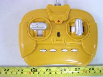
PV5MSD05021990
Jul 01, 2005Dump
Equipment Class
DXX - Part 15 Low Power Communication Device Transmitter